Roman
-
Posts
7,233 -
Joined
-
Last visited
-
Days Won
39
Everything posted by Roman
-
Far out, is this the first vehicle on OS to ever get a WOF first try? Looks like you'll be ready for some summer caravanning in no time! Well done.
-
Does the fuel gauge change scale when it gets low on these? I had Digi dash on the Z10 soarer, and once you got to below about 1/4 of a tank, from memory the bar went back to full (or something like that to show you more detail of low tank) I was driving it once with 1 bar left, and figured "there's always a bit more in the tank" When the last bar disappeared, the car conked out almost immediately haha. What's the plan with the new motor(s) @Truenotch? Planning to get one in the hole before the coming season? Or just whenever they're ready.
-
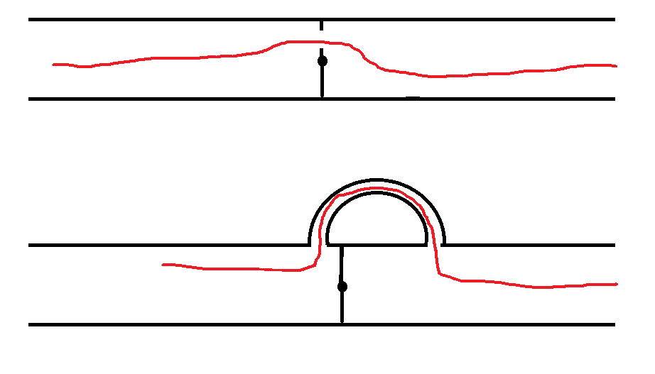
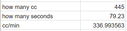
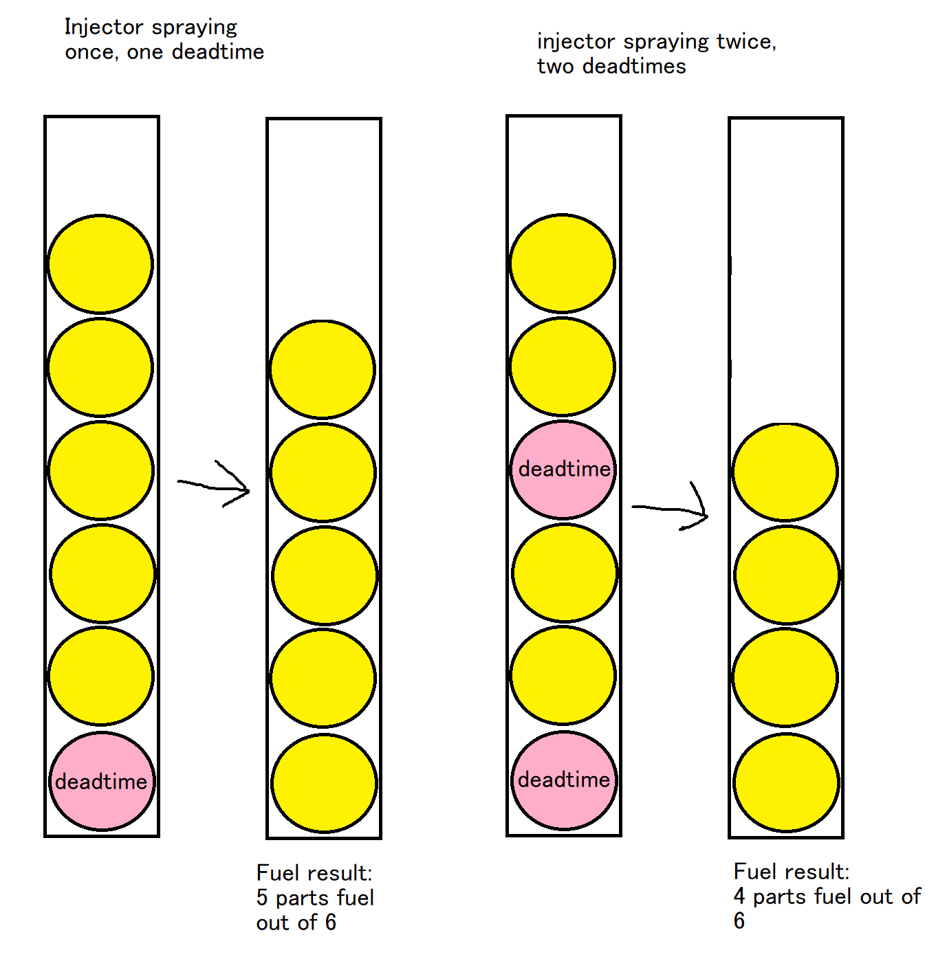
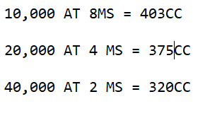
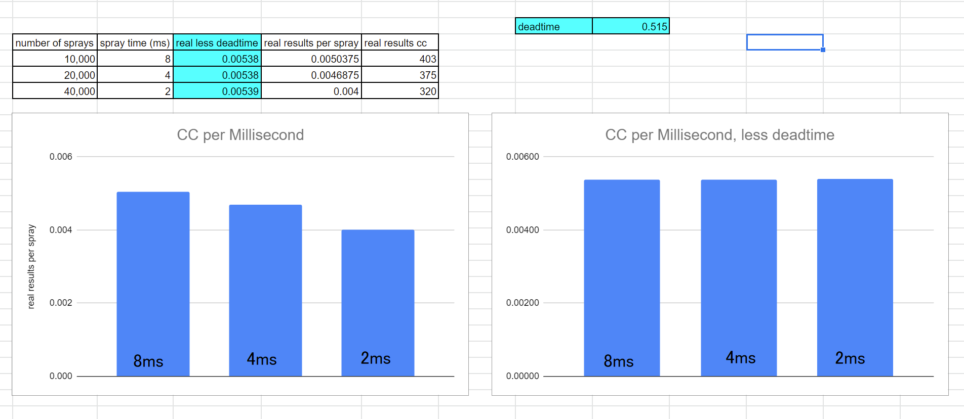
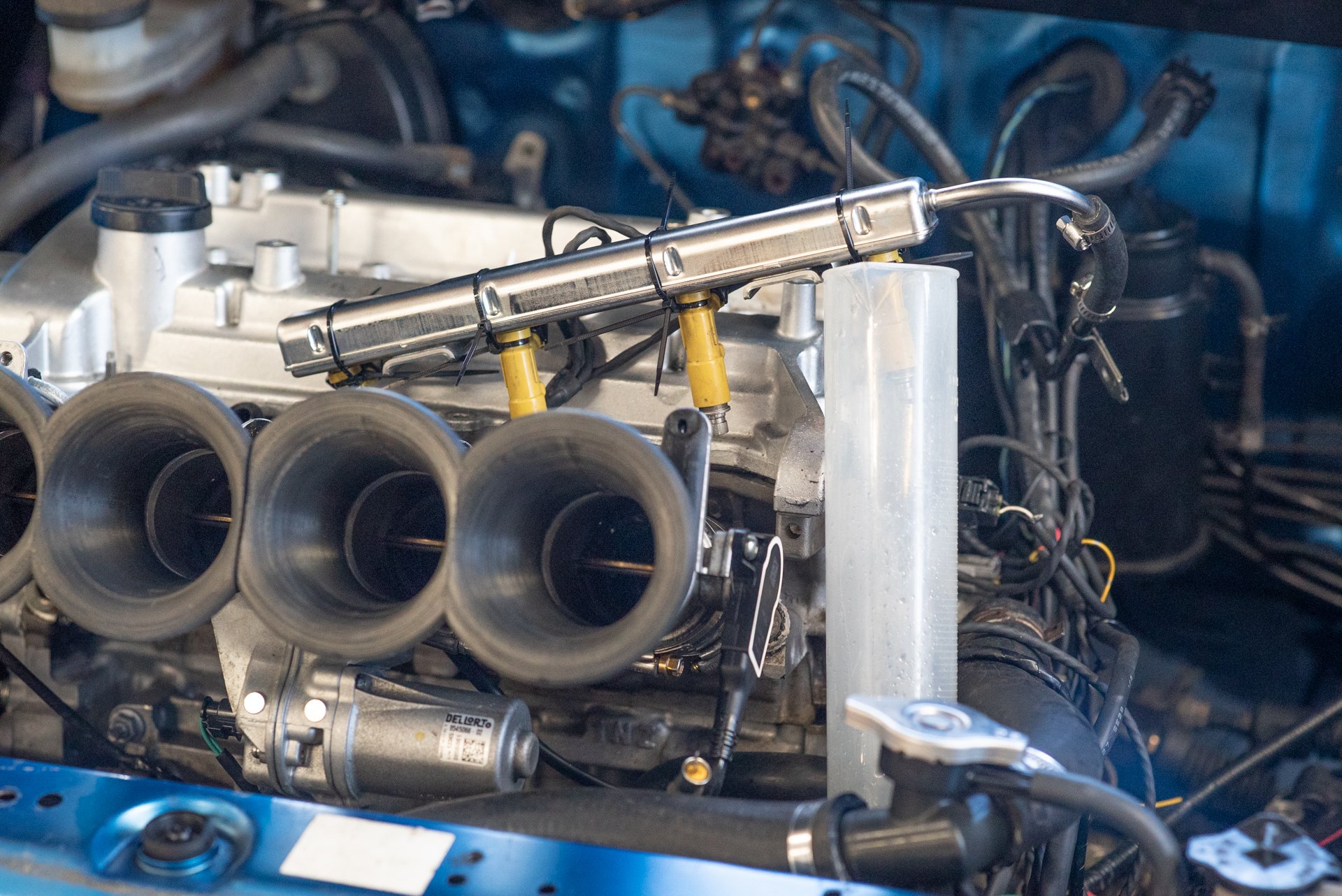
^Might try that vac pump @Stu! If not for the valve, could be good for just running on the booster so I dont need to tap into one of the runners. I found my graduated cylinder so its time for some more fire hazard-ish testing, to try characterize the injectors a bit better. So the first test is just to find the CC rating of the injector. This is simply turning the injector on full blast, counting the amount of time it's open for, then seeing how much fuel came out. So in the ECU I am turning on the fuel pump ahead of the test, then turning the injector on and off using the ECU too. So I can look at the logs and find out the exact time period it was open for. So in this case: These injectors are rated at 305cc at 300kpa, however I'm not sure what my fuel pressure is with the returnless setup. I thought it was 325kpa. However using an injector pressure calculator, it looks like it's probably 360kpa ( 52psi) The next important part is working out the injector deadtime. If an injector could turn off and on instantly, you'd find that spraying 1 time at 10ms would deliver exactly as much fuel as 2 x 5ms. But each time the injector is commanded to open, there's a physical delay until fuel can first come out. So 5x2 does not equal 1x10! As a visualization lets imagine each ball of fuel represents spray time. First instance is how long you tell it to open for. The second result is how much fuel you end up getting. As you can see, by spraying different quantities and time periods that should theoretically give you the same amount of fuel, the results will vary. My first test ends up spraying at 10,000 times at 8ms per spray. Because it's not really feasible to measure just 1 or two sprays at a time. Then second test is 20,000 times at 4ms, then the third is 40,000 times at 2ms. The results are as follows: With some Excel fuckery, we can figure out how much time is missing from each individual spray event, by trying to balance the results. There's probably a smart maths way to do it, but basically I just adjust the deadtime number up and down until all 3 of the columns are the same height. So for yellow 2ZZGE injectors, deadtime is around 0.515ms at 12.6 volts. Ideally you do this same test at all of the different voltages, but this at least tells me the ballpark of where the motor will run at 13.1-13.6v which are the operating conditions. My existing deadtime values were too high, around 0.7ms at that same voltage before. This existing number was from guesstimating by adding 10% fuel to the running engine, and then seeing if the results changed by more or less than 10%. Then adjusting up or down until it sorta matched. Not a perfect method but gets you somewhat close. Now it should be able to adjust itself with closed loop lambda or temperature corrections a little more accurately. It also means it takes fewer iterations to correct the fuel map, if it's off target when testing new runners or whatever. The end result of all this is that my fuel table will end up changing shape a bit. But once it's done this time it should stay pretty good even as altitude or whatever changes.

-
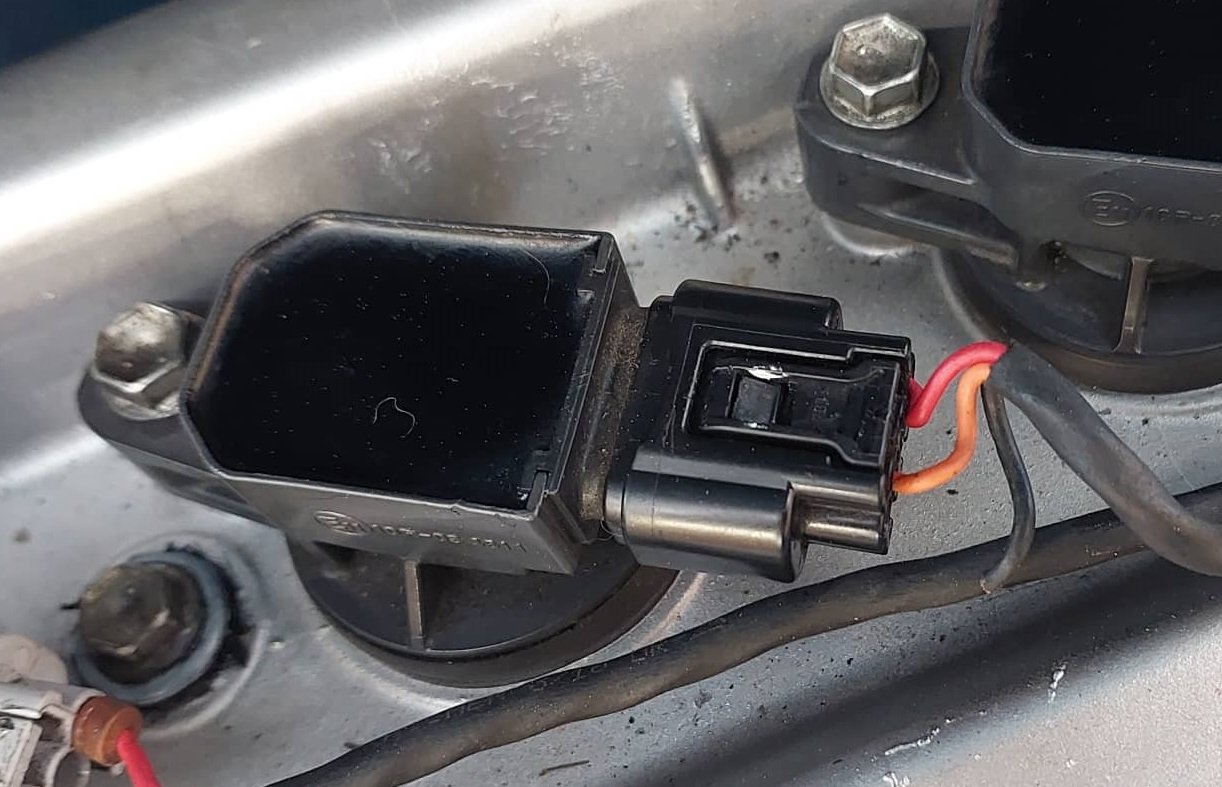
I tried to get the exhaust valve working today. One problem is I've got nowhere good to get a vacuum source. I had plugged up the factory injector holes, and was running the BMW injectors on the throttles now. However it's felt a bit sluggy that way on transients, I think the BMW manifold sits closer to the head normally and has a straighter shot at the port. So it was going to be easier to switch back to the regular rail position, and use the BMW injector ports as a vacuum source. I figured since I'm here, I might as well try the 2016 blue Prius injectors. As they have a 12 or 16 hole injector that should have a pretty good spray pattern. Got them in and drove okay, but reached 100% duty real quick. Looks like they're something around 190cc. So not going to work, or they might be good as inners for staged injection. But then, I'd rather have the ability to switch just to 1 set of injectors if needed. So out they go. I put the 2ZZ injectors back in, at the port location. Car feels a little bit nicer on transients again, but needs fuel map sorted. I've found my graduated cylinder so I'll do some proper tests to characterize the injectors. It's night and day difference for things like temperature compensation, when the deadtimes and short pulse width tables are correct. So anyway, the point of all this before I got sidetracked. I ran a vacuum line from one of the throttles to the exhaust valve, and started the car up. And the valve is rattling like crazy as it pulls the valve half shut. There isnt steady enough vacuum to pull it all the way shut, and when its on part way travel and oscillating. Even if if I link up multiple throttles to a vacuum can, I'll still end up with some load and rpm point where it's just going to rattle. I guess I could fit a VSV to avoid that problem, but I think I'll just chop it back out. If I hold the valve shut, it doesnt seem to make so much difference now that the rest of the exhaust isnt leaking like a sieve. Was worth a try though! Here's a myspace selfie photo angle that hides most of my exceptionally messy wiring.
-
Nah I would lose about 1/4 of my power by turning the lights on
-
Yeah that will be awesome if it does! As that means the entire rpm band that it uses at the drags will be out of the dips. Yeah I'll give the longer ones another go now. Here's some exhaust noises. Doesnt overpower the intake at all. Super happy with it!
-
Yep soon, will just fix the rattles first
-
It's one of those cost saving measures, where instead of having a fuse installed for the rods. The rods are the fuse! I cut the pipe a bit shorter, it doesnt look as obnoxious as I first imagined it would. Might paint it black for a bit more stealthiness. I did some VVTI adjustments, just trying +- 5 degrees from existing settings. Seemed inconclusive, I dont think there will be any major wins or losses from VVTI in this case. However it might work out that a different runner length works better with the current exhaust. So will try some iterations and try get a few sets to swap while at the dyno this next time. I should probably also get back to figuring out a 2nd injector rail setup, so I can test that at the same time.
-
Yep anywhere it needs more fuel, should be some power gains hopefully!
-
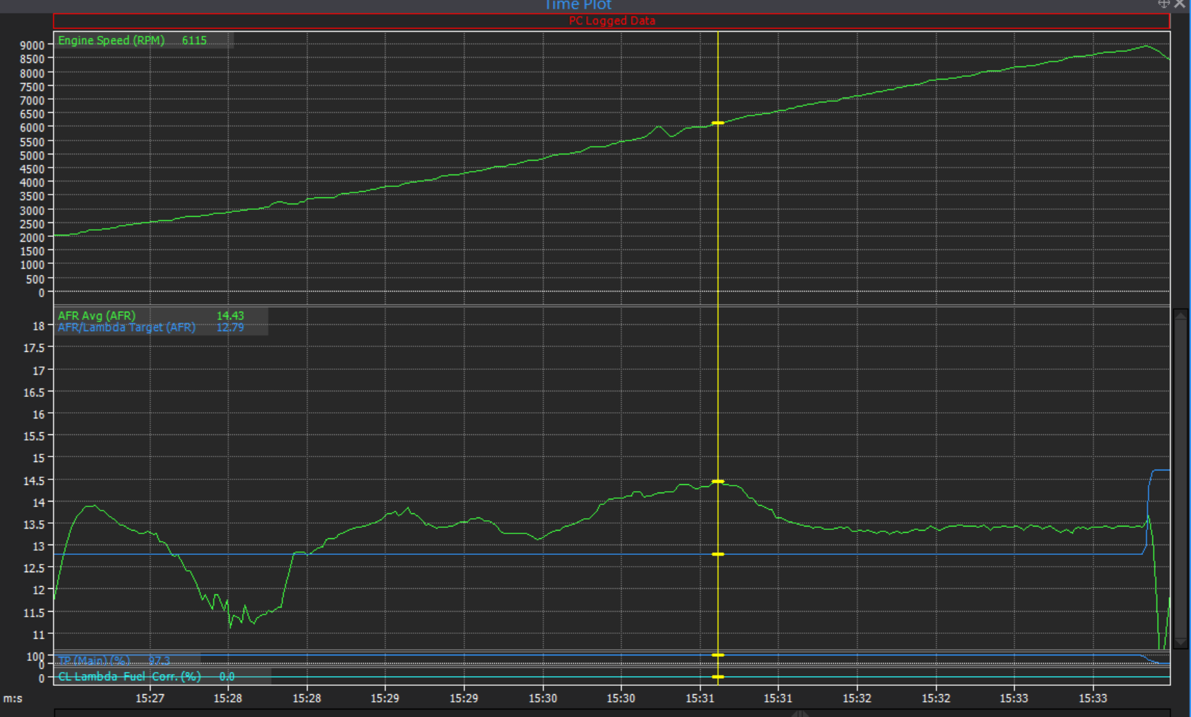
First run with VVTI working, and its looking promising! Using the existing fuel map it's now running lean through the majority of the rev range. Needing nearly 12% more fuel around 6100rpm, and 4% from about 7000 upwards. Any difference in fuel requirements is interesting, as I was not sure whether power difference would come just from reduced pumping losses. (gainz, even if AFR stays same) The road I drove on wasnt great, so virtual dyno results arent useful currently. The cam timing isnt optimized for this setup yet either, I think what KPR said is that it will probably want more cam advance at higher rpm now. I'll have to see if I can sneak back on the dyno some time soon.
-
It's normally open, then pulls shut with vacuum applied. Today I managed to get the rear two parts finished-ish, enough to take it for a drive. There are still a few pinhole leaks to sort, yada yada. But first time taking it for a drive again after a long absence was awesome! Compared to previous tune it was running rich basically everywhere. Which isnt a good sign... Looking at the logs when I got back, either I have forgotten to plug the VVTI solenoid back in, or the pin in the pulley has jammed itself again. As the cam isnt moving from home position. So that explains it! Should be an easy fix. So no meaningful results yet, but hopefully tomorrow some time I'll fix some of the bangs and rattles from the exhaust, and give it another go. The absolutely awesome part of all this though, is that with the rest of the exhaust on, even when the valve is open the motor is a comfortable noise level at idle. At cruising speed it sounds almost the same as before, its well within comfortable limits. At full throttle is pretty rowdy but doesnt sound tinny or gross. I'm super stoked with that!
-

Hyperblade's KP61 Racecar "KP61R" Discussion
Roman replied to Hyperblade's topic in Project Discussion
That's a bummer about the clutch! But looks like it's going great apart from that. Have you noticed much of a difference with handling, with the lighter motor mounted a bit further back? Yeah adding a bypass hose is the way to go. Just see never ending problems with inline thermostat-less EWPs. -
@BiTurbo228 the butterfly goes in series with everything else, its to close down the pipe size to keep the noise down at part throttle. Exhaust progress has been something like 3 steps forward then 2 steps backwards but I'm slowly getting there. Big thanks yet again to @mjrstar for finding a local place that had Argon so I could carry on. Much appreciated. I've been chasing my tail trying to stop the toyota ball joint flange from leaking, I cut it off and rewelded a few times to try get it as straight as possible. But no luck, gave up on it. Bought a regular flange and bellow to replace it instead. This worked wonderfully, the range of movement from this is excellent! And no more leaks. I had a mental block with how to do the hangers. Then I figure, if I do something shitty then I'll think of an idea how to do it better. But I cant think of anything if there's nothing to start with. So I just used some existing bolt holes and bent some bar up. Definitely not a long term solution as it'll pull the threads out of the chassis or bend itself in no time. However, it's a start I guess. It's tricky trying to weld to the body of the car with tig. I fitted the exhaust valve on the end of the flange, and it actually works pretty damn good! I took the car for a bit of a trundle up the road, with the valve wire tied shut 100% of the time. At cruising rpm it sounds... cool. A bit cammy now. It's not boomingly loud and it doesnt have an annoying pitch. I need to go for a drive to Cambridge to get some 3mm vacuum hose before I can connect it up properly though. It will be interesting to see what sort of load it opens or closes at. Hopefully by the weekend I'll have the whole thing finished. Maybe. I'm absolutely fizzing to take this out for a drive but have to be patient or I'll end up breaking stuff. I dont have a good video of how it currently sounds, but this was from earlier when it was leaking from absolutely everywhere and just jammed on the end of the muffler.
-
New paint looks incredible! Man this car is alresdy crazy fast, cant wait to see how it goes with the grunty engine in it.
-
if you've seen how he can stuff these cams in through an oil cap, you'll know that you're in real trouble
-
Yeah I had just changed gears, and was doing just over 7000rpm at time of explodey.
-
Yes that's actually one of my concerns with fitting a much better exhaust now, I will be lessening the dampening effect that my crappy exhaust created. haha! I dont think it was an issue though, as the logs dont show a lean spike happening at the time, and the motor was running great (until it wasnt) I must have damaged the plug recently while undoing the loom.
-
How recently? I called them as well as the place in Morrinsville, no bottles
-
Heh, yes well done. I thought I'd covered this by checking the plugs - they were all looking the same when I ran the 2NZ. But this was probably just because the motor was sending so much unburned oxygen out the exhaust, and I didnt realize it was running on 3, so it was wanting to make the other 3 also run super rich. So one rich looking plug wouldnt have stood out from the others. My second mistake was assuming the rough running was on account of the cam timing being out, that I couldnt be bothered diagnosing any further. So it's a pity to not have run the 2NZ as a comparative data point, but ultimately I'm super happy to get the 1NZ setup back in there!
-
Progress! 1NZ is back in the hole. Not 100% finished but I got it started back up. One of the situations that I have been dreading is that since the cam timing on my 1300cc motor was actually alright, but the motor ran like shit. That there was damage to the head that I'd somehow missed seeing. Maybe a slightly bent valve clacking the seat. So I get the motor fired up, and much to my dismay it's making the same sort of sound that the 1300 motor was. craaappppp I unplugged each injector to try isolate it to a particular cylinder - Cylinder 2 was the one that had the piston blow up. So I unplug the first injector - engine drops, motor sounds rougher. Unplug the second injector - and no change. Crap. Crap! It must have no compression. Check the 3rd and 4th cylinders, and they all drop rpm and run rougher when unplugged. Crap crap crap. I had a sit for a minute to feel disappointed in myself for not checking things better. As it's a heap of work to pull the head off again. Then I took a look at the coilpacks... Particularly number 2... Oh shit! Looks like some idiot (cough) didnt do a very good job on the loom here. So I fixed this, and the motor runs smooth again! So I'll redo the ignition loom in order to give a bit more room for the plugs to undo, as it's always been a bit tight. God, what a rollercoaster of emotions haha. Could this have contributed to the motor blowing up in the first place? I dunno, but its certainly got me wondering if it's relevant. However I think the only way this could be likely is if the piston showed signs of lots of knock. However the top face of the piston is one of the few remaining things that was still okay haha. The good news though, is that the exhaust clearance around the swaybar/manifold with the 1NZ back in is bloody perfect. Big thanks to @kpr for doing an amazing job based on my completely shitty explanation of things. Unfortunately I've run out of argon from the borrowed bottle, (Thanks heaps @mjrstar! legend) I cant go swap it because no one's got stock back in yet. Exhaust still needs some tweaking in a few places and hangers added. I called Coregas, and they're got a shipping container full of argon swap bottles stuck in the docks waiting processing. So I'm a little stalled on progress again. But on the whole everything's coming along. At idle the car isnt toooooo loud with just the single muffler. Even though it's currently leaking from the flexi flange thing ahead of the muffler still. So it might get even better yet once this is fixed. However I've still got no idea how loud it's going to be at full noise or cruising along. My plan B is that I figure fitting an exhaust valve means a lot of the pressure waves get reflected back up the tube, so its like a lot of the energy now goes through the muffler at least 3 times in order to exit. So I can use a VSV controlled by ECU to pull this shut. Hopefully it wont be needed, but will see how it goes. I've been thinking it might be more effective if the valve shuts completely, so waves can reflect completely back up the exhaust. With a small bypass pipe just on a small portion of the diameter of the pipe. Dunno!
-
I had an injector driver fail on my ECU - the mosfets fail "on" so its easy to test if its happening. Because it will just hose out fuel constantly. If you plug in an injector while the ECU is on, without engine running. If it makes a click noise on number 4 then the injector driver is chooched. If you have been having issues with low voltage, and your injector deadtime table isnt compensating then it could definitely cause issues. From 14v to 10v your injector deadtime could be 30-50% larger. This makes the most difference at low load, but could definitely make it run a bit lean at full blast too. Even if your deadtime table was correct, if you had low voltage issues causing your fuel pump to be less... pumpy. then you could be running lean as well if fuel pressure was dropping momentarily.
-
We covered this on page 2 Dave
-
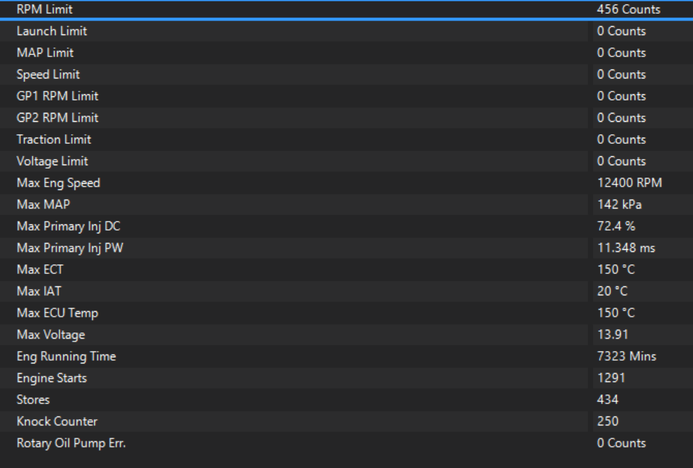
Ahhh right! Well that makes life easy. I've never used that before. Just checking my current stats, I must have unkowingly reset it at some point. The numbers are too low for it to be all time numbers including Carina usage. 122 hours total runtime. I'll reset the stats for the new motor. A lot of these stats (like 150deg temp, or 12400rpm) are from things like a sensor being unplugged or trigger errors when first setting things up.
-
I think there's a way I could achieve this. There's two ways that my ECU can do logging. You can plug in the laptop, and it records everything to that. Or you can record to the very limited onboard memory when certain conditions are met. I never really use the onboard logging, apart from when I want to look at something with a bit more resolution (as it's 100hz vs 40hz) Since the amount of memory is small, you also need to economize which values you want to record. However, I could setup a trigger condition so that it just just records engine rpm only, at say 1hz resolution. Every time the motor goes over say 8000rpm. Then when it blows up I'll have a log of hours spent in the danger zone... I'll be honest though, when that last motor blew it rattled me a bit. I felt lucky not to have started a fire or skidded on the oil or something. (or oil filter...) It would give me the shits to do that at a track day at higher speed. Longer term the stronger pistons and rods will be a necessity for safety's sake more than anything, I think. One interesting thing that I've noticed since I've blown holes in my old block. Because the factory pistons and rods are so light, (I guess?) there's only one counterweight per cylinder. Also, here is a shitty time lapse video with some annoying generic music, of pulling a big bunch of junk off the motor.
-
Yeah I've got a set of Maxspeeding rods, same brand KPR uses to spin his 4AGE to 10k rpm. However, yeah it needs the pistons to go with it. I'm definitely keen to build one with forged pistons as well, but not quite yet. One of the companies makes forged 1NZ pistons for a 75-77mm bore, and anything from 7:1 to 15:1 compression ratio custom order. For around $1000 a set. Boring it to 77mm would take it to about 1570cc. But all this means the car's off the road for much longer, and costs go up considerably. I'll be keen to order some once my life is back on track with house situation though. My big goal for the moment is get it all going with a standard block, get back to the dyno with the good exhaust and see what happens.


.jpg.fd41d87dccbda5aa50da3ce23e63c7af.jpg)