Roman
-
Posts
7,233 -
Joined
-
Last visited
-
Days Won
39
Everything posted by Roman
-
Hopefully smaller motor will sound a bit more "snappy" too. Ive been thinking that the guy who made that v12 video. Was obsessed with the idea that equal length 6-1 on each side made the high pitched sound of the zonda. But I wonder if having more tail pipes changes the pitch too. As in, if you have a 6-1 collector that then splits back out to 2 pipes, and the accoustic length is slightly offset. It might sound like twice as many pulses. The zonda has 4 tail pipes, not sure what happens upstream of that. But maybe thats similar to x pipe on the likes of an mr2. It will be fun to do some experimenting and try tune the sound once its all together.
-
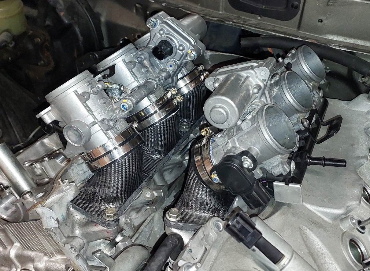
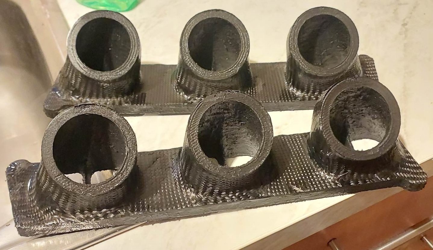
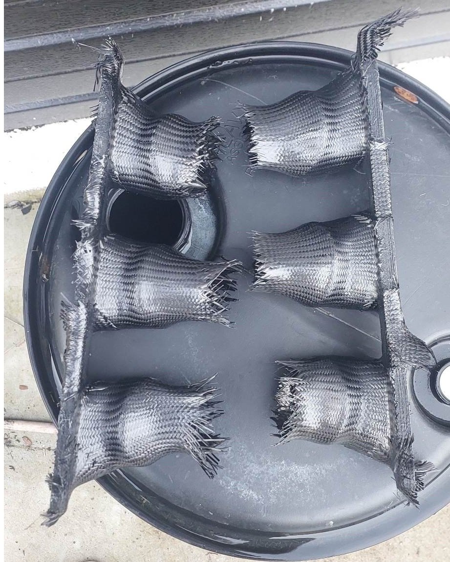
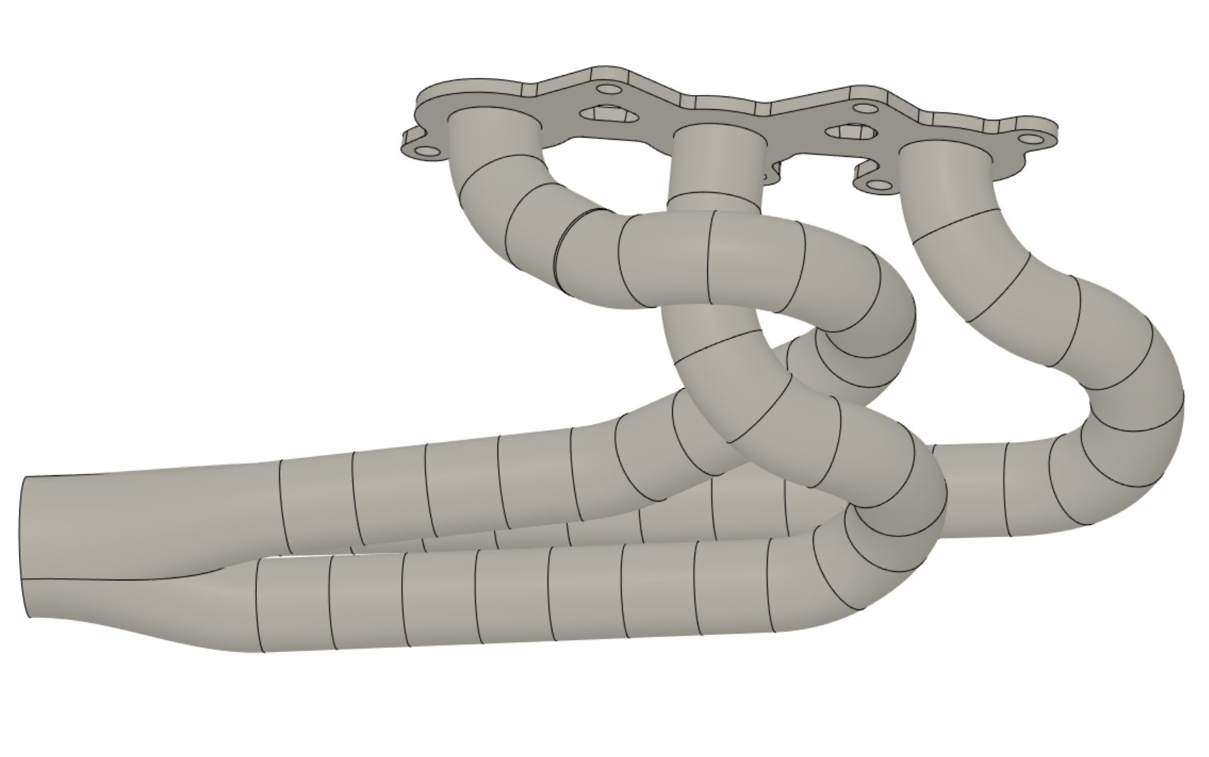
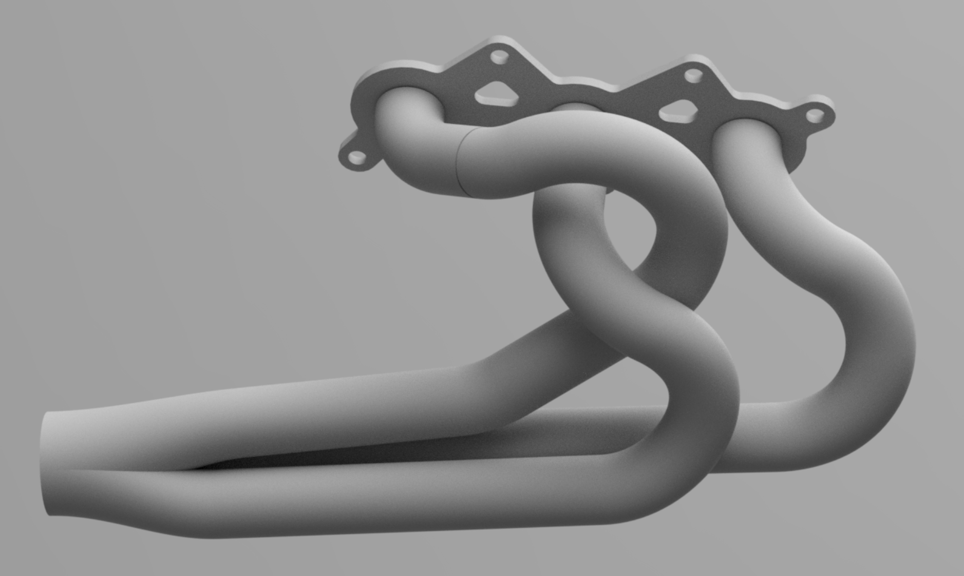
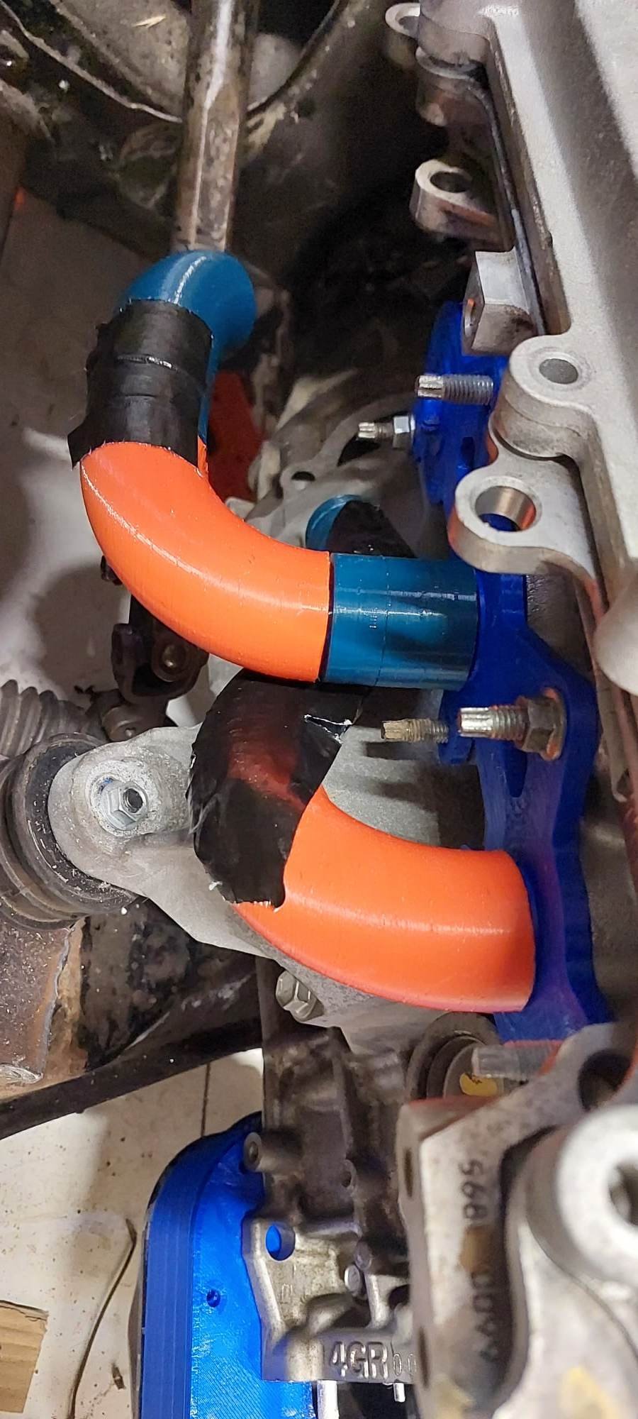
Mike Tyson was famously quoted as saying "Everyones got a plan until they get punched in the face" Well, thats about as well as my equal length exhaust lego has been going. haha. My scheme for equal length was nowhere close to working, mainly because of the engine mount below the middle cylinder making life hard. It's also been difficult because of the Vee angle - you can make a nicely fitting thing that works. But then you cant get the damn thing on or off as it wants to hit the chassis rail. So it's looking more like it'll need to be a bit more compromised on lengths until everything's past the steering column. then can maybe do some swishy bits to bring them close to even again. So, what do you do when something is too hard? Have a sook and ignore it. So here's some progress on the intake. Same recipe as the echo, which seems to work well enough. CF nylon PA12 print, then carbon sleeve over the top. I've been talking to @flyingbrick about our concurrent CF projects. I thought I was making some manifolds, but turns out I was making a 6 pack of chodes Then tidied up a bit Then very nearly finished!

- 131 replies
-
- 52
-

-

-

-
I found someone who's made a 2GR sound less awful than most. So it has equal length 3-1 manifolds that then they go to an X pipe which carries on to two pipes out the back. There was a nicer one on FB but I cant share it here. But this is more like the sort of exhaust note I'd hope I can get. This is still doing some sooky rpm limit on factory ECU. So will be way better with another 3000rpm or whatever, and some ITB noises!
-
Yeah I did find one alternator at pickapart but the front pulley felt a bit stuffed. Interesting about the clutched pulley on the front. I saw there's reconditioned ones with a new front pulley for $300something on trademe, so probably just go that way when the time comes. I've considered bodging something else on there that's more common (Have got a few 3S / 1NZ alternators) But I've got enough other issues to sort currently.
-
Ahh, thanks I hadnt thought of that. I'll get some pics and take some measurements
-
Some boring bits of progress. I've been trying to find injector plugs for the Triumph injectors. After a while I found that they are the same as late model Hyabusa ones. I'm still looking for the e-throttle plugs, hopefully these are something sort of generic as well. But I might just put a lead and another plug on them. I've finished wrecking porting the heads, I ended up tapping a thread into the direct injection plugs, winding bolts in and using high temp loctite. I'd not do this again as I've ground the ends of the bolts flush in the combustion chamber. But some of the sharp thread ends were sort of exposed. so I've had to try grind down the threads on the sides as best I can to avoid sharp edges. Next time press something in, instead. I've printed two inlet manifolds from carbon nylon, as "final" versions read to run with. Just need to cover in carbon sleeve then they're done. I printed some clip together exhaust manifold block things when I was mucking around with the Echo. Since this will use the same sized pipe, figure I'd repurpose and see what I'm up against. The hardest part will be dealing with the steering column and getting around it. Options are obviously to either hug close to the engine block, or go around it the far side of the column. The problem with hugging the block is that it will work for the steering column, but then I cant do the same on the other side of the block. Because the starter motor is in the way. So I think I'll try go outside-outside, so I can reuse same design on both sides. In order to try get some equal(ish) length runners. In my model I've cut the pipe into 30 degree segments. Then measured the length of the arc of a 30 degree segment. Which was something like 30.2mm. Then the straight bits are 30.2mm long. So this means, if I've got the same number of parts on each runner, whether a bend of straight. Then the runners are equal length, or there abouts. Using some measurements I've come up with a scheme that I'll try make fit with printed bits in the car. This might end up hitting my engine mounts though. Or possibly the alternator on the front of the other bank. I'm going to try make something along the lines of this fit. It's 18 segments each per runner, and I can still get to all of the nuts on the flange easy. One of my other attempts to go on the inside of the column meant it would be very difficult to get the manifold off or on. I also ordered some flywheel bolts, I found the part number from the factory manual IS250. My engine didnt come with a starter motor or alternator. These two things seem to evaporate instantly on the pickapart cars. However I managed to nab a starter motor from the Tauranga branch. I really need to get an alternator fitted so I know how much room I've got for the manifold on that side. So, little bits of progress on lots of topics but nothing really ticked off the list. Will get there!
- 131 replies
-
- 36
-
-
It's not good for the sensors to leave them in unpowered for long time. So you'd probably want a bung on one side them swap them over. However after initial checks to make sure banks are balanced, probably just sweet on one side and left there.
-
Or you could just mount it further down stream if all 6 converge to a single pipe I guess.
-

Hyperblade's KP61 Racecar "KP61R" Discussion
Roman replied to Hyperblade's topic in Project Discussion
Hey I've got a standard S1000RR airbox - but I bought the wrong one. It didnt quite fit because it must be the box for the slightly different variation of throttles from the earlier or later ones. However it was definitely interesting to look at the mechanism for how it adjusts trumpet length, and the injector positions. My consensus was that it was interesting to look at, but I dont think it would have added enough benefit for a car engine to be worth buying another one that fit correctly when adding to a car engine. What I mean is, the box has shorter runners for higher rpm. But those bikes run to 14,000rpm so "low" rpm might be below 10k haha. It's got a massive span of rpm it needs to operate compared to a car engine, which is why I think the dual length runner was valuable. Also why the outer injectors earned their keep. It was also interesting that the position of the outer injectors was so incredibly far from the runners, when the upper trumpets were lifted up for high rpm. It must have essentially just been fogging the whole airbox. Like maybe... 150mm away from start of the bellmouth. I will take some pictures and measurements when I'm next over where it is. Can send it to your for cost of post if you're interested but it wont fit. -
Hyperblade's KP61 Racecar "KP61R" Discussion
Roman replied to Hyperblade's topic in Project Discussion
Okay soooo They had 184.5 wheel horsepower. Then fitted ITB, and now they have 185.6 wheel horsepower. So a 1.1 horsepower gain in real life. But they now for some reason have 60.4 horsepower drivetrain loss instead of 56.6 horsepower drivetrain loss. Did someone pour sand in the gearbox when doing ITB swap? haha. This is why I hate "at engine" power figures. -
This is going to sound incredible. Hope you've watched this vid - please build some 6-1 manifolds for it please
-
He has also been turd polishing toyota hybrid engines (2arfxe) ...havent seen any mspaint yet though.
-
Hyperblade's KP61 Racecar "KP61R" Discussion
Roman replied to Hyperblade's topic in Project Discussion
Nice work on that DTM panel! Looks good, been thinking about doing something similar. However will you be doing anything to index them or add a keyway or something, so you cant plug the wrong plug into the wrong one? Or colour coding them or something. (I'm here to steal ideas) -
Some results from the 3500cc motor running same cams as I'm planning. 405whp on E85 at 7500rpm. So if I could manage that same power/litre would be around 290hp at wheels. Yikes! Hopefully keeps pushing powerband up more with smaller motor. The motors are obviously a bit different so there's no assurance mine would react the same. Also worth noting that these results are great but it sounds pretty yuck. Would probably sound nicer with some longer manifolds rather than short 3-1 setup. I'm still considering how I could fit a 6-1 manifold after @h4nd poisoned my brain with amazing engine noises with that V12 video.
-
Hey, Ive run a bunch of printed manifolds. My ones that can last well for a long time are made by printing nylon filament that has carbon fiber in it (just helps prevent warping really) then I wrap these in carbon fibre which is epoxied on. This way the 3d printed material gives the nice accurate geometry while the carbon gives it the strength. Its more economical than trying to make something just printed (need a lot of filament to make it strong) or just carbon (complex and time consuming moulds) Its obviously not as good as an aluminium part. However if you want to test the concept before going all in on casting. You can run a motor with them. However even this option will set you back a couple hundred bucks on materials... and thats if your printer can reach the temps needed to print nylon. So either way gotta spend some bucks.
-
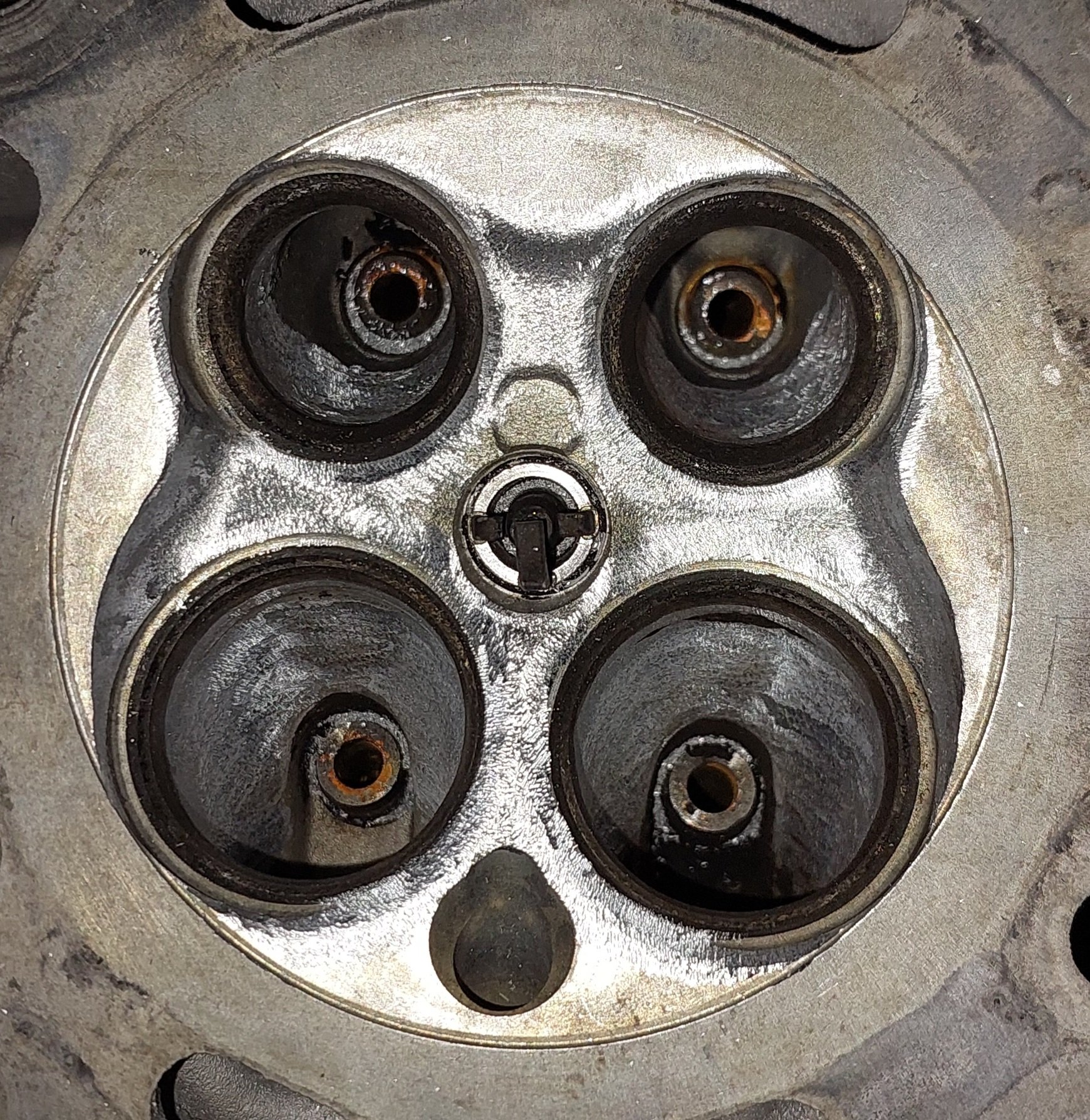
Not sure. I guess running a catch can would help, its probably a lot to do with oily buildup from that. But the valves were almost road cone shaped with shit piled on top.
-
Interesting. Im guessing a lot of these things are necessary for stratified charge, but less relevant when youve got high up port injectors. Will eventually buy another motor or 2 to try some other stuff too.
-
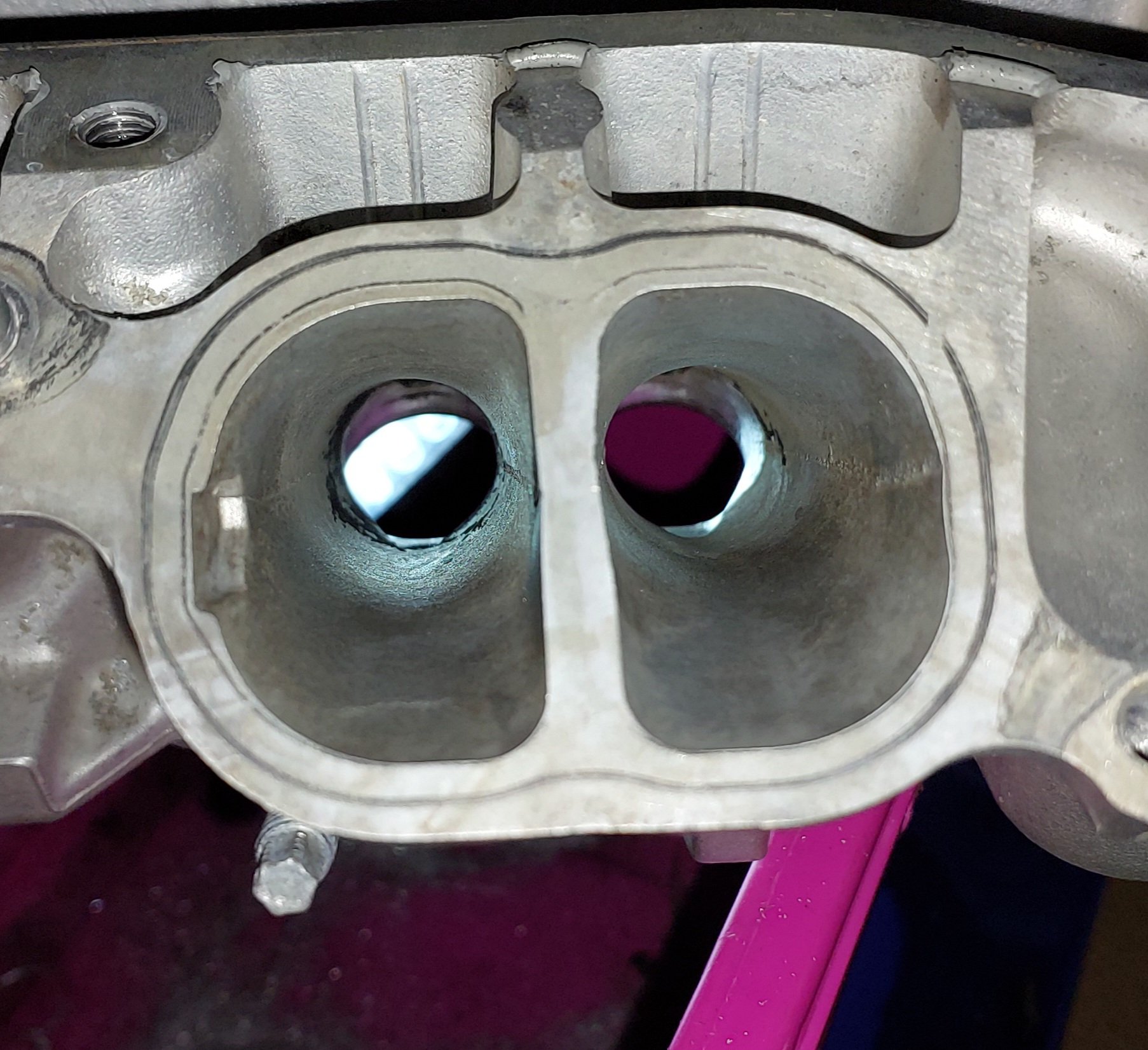
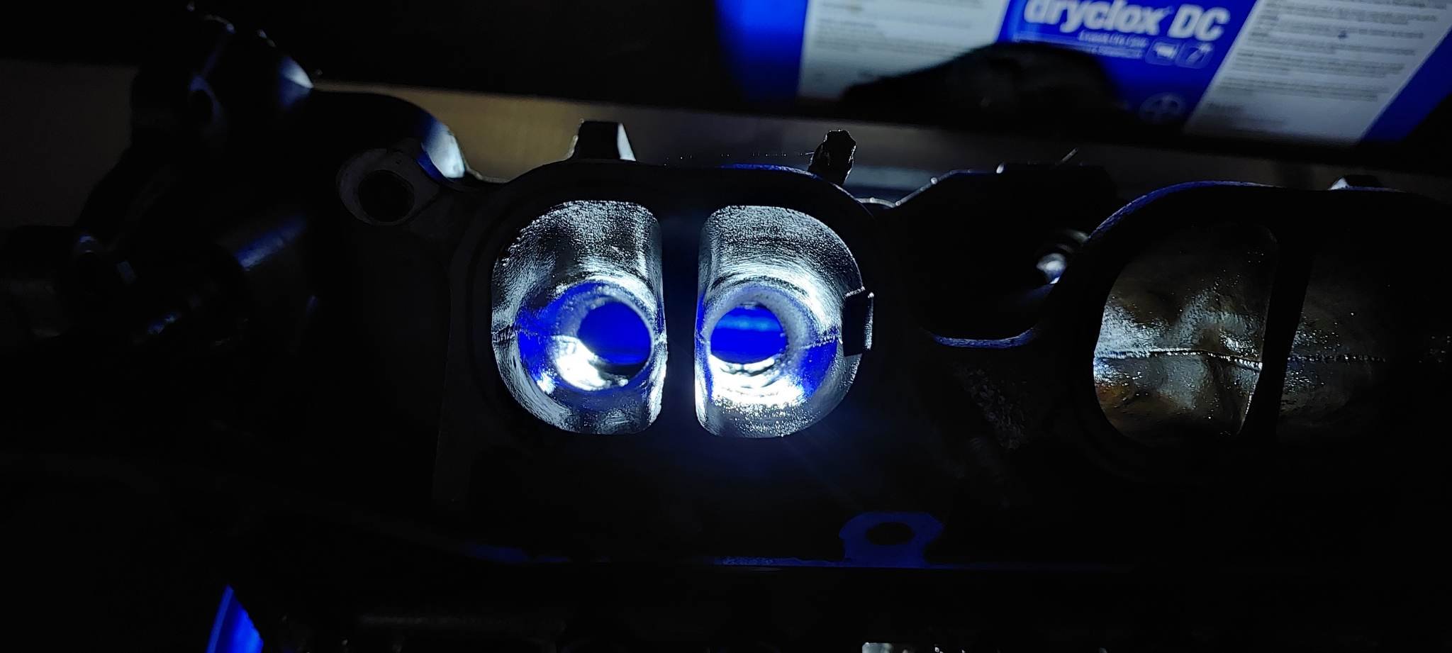
Got it more cleaned up and started molesting it with the dremel. I decided that since the valves are small Im gonna need to try deshroud them as best possible. Even if that means increasing chamber volume slightly. Since the direct injector will be gone now, if I can get the hole welded up then it will more than amount to the material lost. So ive been putting a radius on the squish bands. Maybe good for flow but probably bad for combustion goodness. Might reduce knock resistance a bit.ive left the side ones alone except for the exhaust area, but might carry on the profile. in the ports there is a very intentional step on the short side radius, and some naca duct shaped geometry on the lower wall leading up to it. Likely to tumble the air around the corner for good mixing or whatever. However it blended fairly nicely back in to make a more normal curved short side radius. The intake and exhaust ports are remarkably smooth for a factory cast finish. Not really any point doing much to them. There is a huuuuuge amount of taper in the runners, could probably fill in 50% of the port area at the top - but will leave it for now. Im considering cutting the divider shorter but this might be a job for cnc. But again, will run it this way for starters rhen make some incremental improvements/failures later once its running.
- 131 replies
-
- 28
-
-
That looks so good. Well done
-
4V Century V8 powered Dyna Camper Discussion
Roman replied to HumberSS's topic in Project Discussion
There's no point in a 4-2-1 on a V8, and a 4-1 doesn't achieve the same scavenging effect as a 4 cyl engine. A 4 cyl motor has an evenly spaced 4-3-2-1 (or whatever) firing order. But the v8 firing order means there isnt an even spacing. Which is what gives it that V8 sound rather than sounding like 2 4cyl motors. V8 is more like it fires in pairs quickly together, a gap, then pairs quickly together (shortly after each other) There's still benefit to having a tuned length runner though, you'll probably want them as long as is practical. One benefit of long primaries is that any difference in length between the pipes gets reduced as a % of overall pipe length. -
Yeah theres a bunch of mark x at pickapart. Id not be surprised if all of the motors are fucked and thats why they are there. My motor had not that many kms and its so absolutely full of caked up shit. Id not be surprised if all these cars start going extinct around 200,000km. Direct injection without port injection makes for a short lifespan.
-
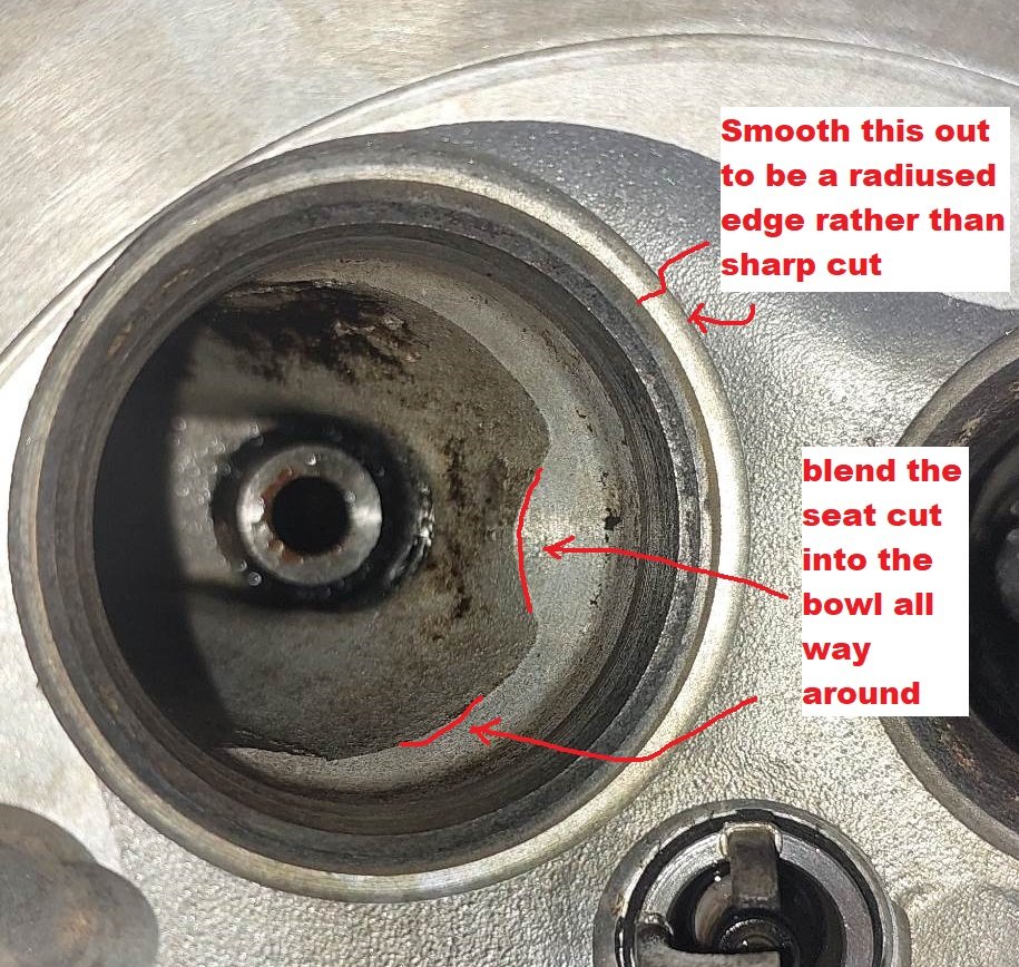
Looks like intake valves are ~1mm bigger diameter than a 1NZ, exhaust valves same size. So if it made only exact power per cyl that the 1NZ did, (per cyl, not per litre) that's... 225hp at the wheels. However, it'll have the advantage of considerably more lift, more duration on the cams. And then more space around each valve to flow, and a shorter stroke. So I think it's realistic to expect a bit more than that. Some insanely straight ports! This below is a picture of the bowl/seat arrangement on the intake side. Definitely some room for improvement by blending the bowl cut into the casting a bit better. Then will smooth off the outer cut edge on the very outside too. The short side radius is basically absent / incredibly gross - I guess that's one downside of a super straight and high angled port. Not too sure what to do there, it feels like instead of a curve there it might just be the back side of the seat sticking out to form a square edge. Maybe it is like that to tumble the flow around the corner or something. Will be a tricky spot to get to if I decide to fuck with it. So on the intake side, probably the only "porting" that I will do will be in the combustion chamber / bowl. There's not much point doing anything to the big straight section. But on the exhaust side, the port is TINY, definitely less cross sectional area than a 1NZ. So this will likely benefit from being hogged out as much as I can get away with, without hitting water jacket or whatever. So, probably a good idea to do the exhaust first in case I fuck it up.
- 131 replies
-
- 20
-
-
Low compression. No aftermarket parts. Stupid scissor cam gear thing. Dunga power as standard. No vvti on the 2500cc Cheap though. Likely all have a zillion km on them though. If cams and valvesprings were available id consider it. Would bolt to j160 is a feather in its cap.
-
There are some other interesting short stroke contenders, will add in the Alfa 155 DTM motor for interests sake. These are all 2500cc V6 Looks like 2MZFE is the closest in spec to the alfa motor interestingly enough. MZ series motors suck though. Bore size: 4GR: 83mm VQ25HR: 85mm 2MZFE: 87.5mm Alfa: 88mm Stroke length: 4GR: 77mm VQ25HR: 73.3mm 2MZFE: 69.2mm Alfa: 68.3mm
-
Shit yeah, looks great!