Roman
-
Posts
7,233 -
Joined
-
Last visited
-
Days Won
39
Content Type
Forums
Downloads
Events
Gallery
Everything posted by Roman
-

Discuss here about Yoeddynz's little Imp project...
Roman replied to yoeddynz's topic in Project Discussion
He is absolutely killing it! (project progress) I am absolutely killing it! (my engine) -
Probably more, didnt you know its an f1 engine?
-
I cant see how they're related either. Only thing I can think of, is if the debris under the valve then caused a bit of a jam on the pulleys or something. Or it's truly a coincidence and the timing chain stuff was just a timebomb waiting to go off. As the part that is bent on the exhaust pulley, is just something that holds the return spring in place. The pulley itself is still "fine" but that part is only pressed in place I think. Might need to clean them up and tack weld them in place.
-
Discuss here about Yoeddynz's little Imp project...
Roman replied to yoeddynz's topic in Project Discussion
So stoked to see this driving, how good! -
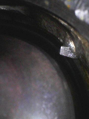
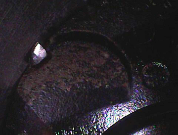
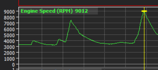
Everything was going so well! Until it wasnt again. So I had the motor warmed up a bit and was getting sensors checked and all that. Gave the motor a few big revs, because, reasons. Was fine after that but then started clattering while the motor was just idling again a bit later. So by coincidence I bought a USB borescope camera and it turned up today, an absolutely excellent tool and it was only 20 bucks or so. So I look down the intake ports and as luck would have it there was a little piece of something jamming one of the valves on cyl 1. So that explains that! So although its starting to rain and the car's outside, it was going to bug me if I dont try get this knocked back out and see what it is/was. I knocked it out of place with a screw driver, however this didnt really unlock any secrets because now it's just the same looking thing but sitting on the piston. Ha. However it doesnt look like part of a screw or anything, so I guess that says something in itself. Since last time stuff happened, it knocked some of the rockers out of the head I thought I'd better take the cover off for a look. And there was a bit of something in there as well? What the hell? Looked like metal and plastic. Hmmmmmmm chain guide? So I have a look at the chain guide between the intake and exhaust cam, and it's broken off the bottom guide part. So that's probably something that I should have just replaced after last time. Because the chain guide on the other bank was broken, but I kept this one in place. Damnit. So I'm not sure what is cause or effect here but the exhaust side VVT pulley looks like it's on the verge of prolapsing as well. Some of the parts of the tensioner have fallen down the timing cover so it's all got to come back off. So yeah that all sucks. But how good did it sound! For a bit! haha. I've got plenty to carry on with that doesnt need the motor going, so this doesnt really set back my timeline by a considerable amount. I'm still on course to have this all going and hopefully at some events for summer time. If it turns out that these VVT pulleys are just going to keep shitting themselves, there is a non VVT version of this motor. So hopefully the pulleys are interchangable. I'd not lose too much sleep about removing the exhaust side VVT, and apparently these are the most likely ones to cause issues.

- 131 replies
-
- 37
-

-

-

-
Spoke too soon, its dead again Well, while it was just running with a high idle it just started making a loud clattering noise so cut it off. Coincidentally I bought a bore scope camera today so stuck it down all the ports to see if anything interesting. So some debris has banged itself into the valve seat on one of the intake valves. Bummer! Not sure where this came from, as this is on the head where the valves bent previously. So everything was disassembled, cleaned, checked etc. I'm thinking it's either bad luck of sucking something into the intake. Or there was a little piece of metal rattling around in the exhaust manifold, that got sucked back into the cylinder. Or maybe undoing the spark plugs and some debris fell down into it. Might be able to identify what it is when I pull it apart again. Not sure but either way if the valve seat is damaged then this head is a write off. So it's hard to know whether it's worthwhile carrying on with this motor, or just buy a whole new one. $150 for replacement head from PIckapart or $700 for a whole other motor from the wreckers. The oil got a little glittery from when the pulley blew up, so maybe it was on borrowed time anyway. Either way, although this is yet again fucken annoying. It doesnt stop me from progressing with a bunch of parts that still need doing.
-
Hah yeah still a few issues before I can do some skids. It's looking like the gearbox has a leak on the front half which is annoying. It's a motor/box out job to fix that properly. Maybe there's a loose bolt or something but I'll have a better look on a nicer day. I'll need to get the radiator properly welded too, my carbon fibre patch leaks a little when it's pressurized. So, some issues to fix but it also passed one of the tests today: Valvetrain is still intact. haha. I'll try get the car driving and/or to the dyno first before I push it too much more. Lots of fiddly little bits to sort.
-
Standard exhaust manifolds and some coby hotdogs on it because I just wanted to see if it fired up okay. But... shit yes
- 131 replies
-
- 47
-
-
-
Yep adding a little star shaped bit in the middle has been the plan. Welding the collector itself wont be a problem. I probably didnt explain it too well, what I mean is that when all of the pipes are parallel they slot in fine as they are hard up against each other. But when you get to the first bend, where its welded there isnt the same space anymore. I could probably remedy this buy just buying the longer bends that have the straight parts as part of it, rather than needing welds at that point. Now that I've got a design that works/fits, and looking at the shape that everything needs to be. I think I could probably simplify the design to only a 3-4 pieces per runner if I bought some of the bends that have the long straight sections attached.
-
This car is super cool @doullama, keen to come check it out some time!
-
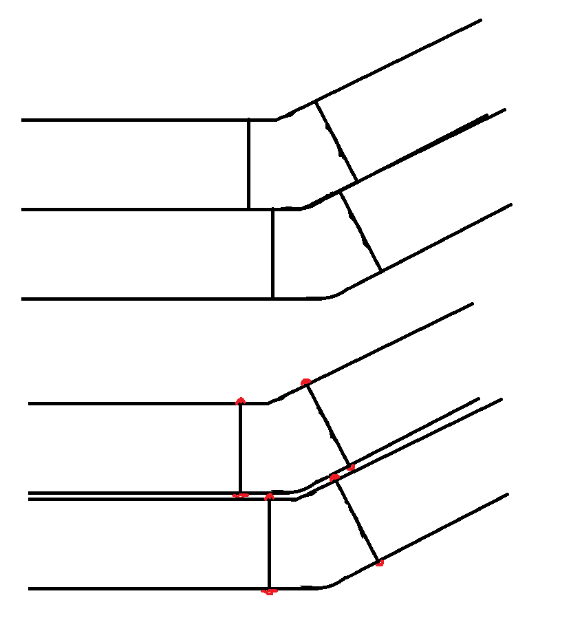
Alright so my welding is definitely improving, but, still sucks a bit. I've blurred this image so you can get the gist of what's going on, without causing too many eye bleeds to people who can weld good. My tig skills have been slowly improving a bit throughout the process so far. I've also learned some better techniques for making a manifold. So here are some lessons for next time. Wrong flange material I had the flanges cut out of mild steel, no idea why, think I was just trying to save money vs stainless. I should have just made them stainless as they are already rusty. Maybe because I left them outside for a few months? who can say. Tig torch angle is crucial The big "aha" moment that I reached part way through this, was just how well it pulls the weld pool along when your torch angle is just right. And, recognizing the symptoms of if it's too steep or shallow. A lot of my welds previously had to run really hot because it was hard to try get the pool to move. So end up with big brown heat bands around the weld. Where on a few where I've been able to keep the torch moving fast, ends up with the nice rainbow sort of finish from a much smaller heat affected zone. Cool. I've had a few blowouts which has been annoying, but they are decreasing in frequency with practice, and there are a few welds there that I'm happy with how they look. If someone reading this hasnt tried tig welding before, basically getting the tig torch on the right angle is like when you get "scissor glide" through paper by having the blades in just the right place. Aahhhh. Satisfying. haha. Slot the pipes right through the flange On the flange, I had some holes cut that are the shape of the port, rather than shape of the pipe. So the pipe has to sit on the top face of the flange, it's only held on by a fillet weld around the outside. So this makes positioning the pipe tricky, and it's probably more likely to break off or crack later on. It means that the tack weld has to be fairly grunty to hold it in place, as there's a lot of weight hanging from it. It would be super easy if the pipes just slotted into the flange instead. So this way if It's all tacked together and I just need to extend or shorten the runner by a smidge, I can move the pipe in or out of the flange. Only small tacks are needed as it's supporting much less. Then once it's all welded together, you can just cut the excess pipe lengths off at the back. Might save me needing to do some tricky welds on the front face of the flange as well, if it's hard to reach. As I can just fully weld the pipe from the back side of the flange. Collector doesnt allow for welds between pipes For the collector, I've had fairly tight clearances for the 3 pipes to go together parallel. This has become a pain because there's no allowance for the thickness of a weld where the pipes touch each other. So the pipes want to splay out unless you grind the inside welds flush. It would make life waaayyyyy easier if I put something like an extra 10mm or 15mm on the outside part that the three pipes slot into. This will add some strength but also make it a lot easier to hold the pipes straight when trying to reposition them. U bends for easy length adjustment For getting pipes equal(ish) length it's awesome having a 180 degree bend in the runner - Because if you need to add 300mm, you can just cut 2x 150mm extensions and add them to either side of the 180. So far my first two pipes look to be within 20-30mm of each other with a goal of 860mm total length. (for the arbitrary reason of, the first one was 860mm) Hard part first Making the first pipe fit was the biggest headache, because once it was in place and cleared the crossmember and steering column. It was easy to put the others into the available space. It was good to start on the most difficult side, As this sets what the overall runner length can be, under the most difficult circumstances. So its al lot easier to try match it up on the other side that has more room, than come up with a length that is a nightmare to fit. Hopefully I'll have this side all finished this week. I only ordered 1 collector, so I'll add some revisions before sending off for the 2nd one to be made. I'm going to order a crapload more bends, as I might actually run out before finishing the 3rd runner. Despite thinking I'd have plenty.
- 131 replies
-
- 38
-
-
-

-
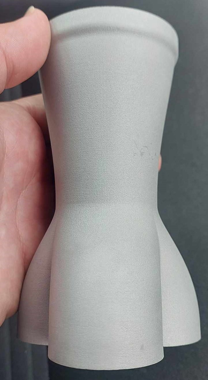
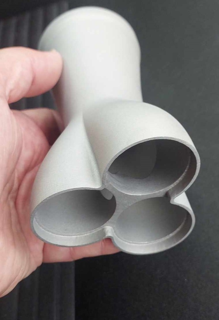
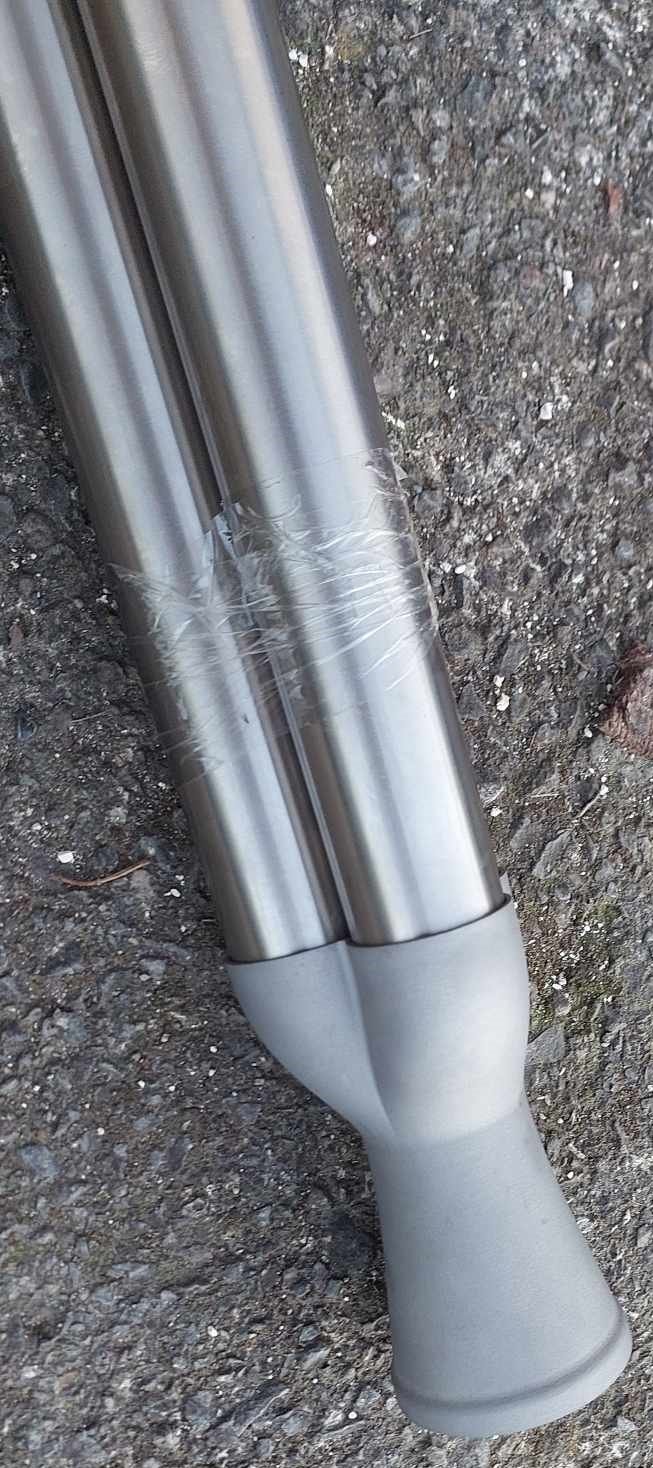
The idea from the start has been to weld the three tubes together on the inside first, before they slot into the collector. Then the only weld to the collector happens around the outside. That's the plan at least... Also, the alloy bits turned up and they look cool as well. Not quite as nice as stainless. But to be fair I threw what has to be a worst case scenario at them, with lots of small fiddly details.
-
Yeah definitely want to try print as little as possible to keep the costs down. By which I mean, anything that is low mass and high complexity is worth printing. But you wouldnt bother printing a beefy flange or some straight pipes. But combining printing the complex sections, with some milled flanges and regular straight sections and you could make something awesome that would go together easily (says me thats never done it) My intake manifold is "okay" but wont last long term. So I'm thinking it would probably be a good scheme to mill a piece of 6mm alloy as a big flange on the bottom, then have 6x 3d printed parts with the complex shape that slot into it.
-
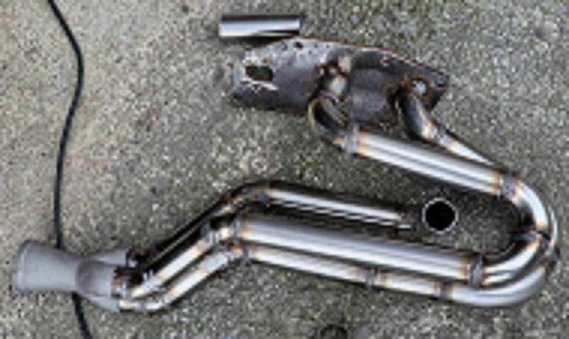
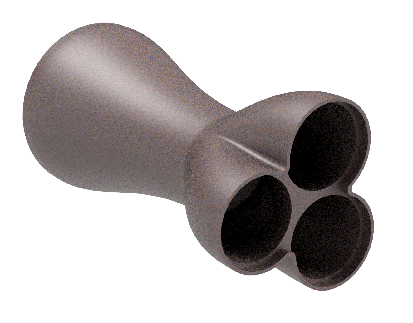
Alright alright alright! I'm all fizzed up at the moment about making some good progress again. The motor's all back together and ready to fire up, apart from exhaust. I've nearly finished making a 3" exhaust for it, apart from extractors. Just need to hang it and finish off some of the welds. Had a few blow throughs on a few areas, some of the bends were a bit shit, think they are thinner than advertised. It's not pretty, but, it'll do the job. Radiator fan has turned up, so will get that mounted and wired in. I found some 90 degree boots for the injector plugs so my loom is a bit tidier. As currently they want to sprawl out across the top covers. Carbon rods turned up, but yeah they are nowhere near 10mm. More like 10.5 maybe. Too big to work as the throttle rod things. I sanded one down heaps, but still super tight. Might be able to use a lathe or something to try get it nice and even and 10mm. However CBF with that for now, it's a bit of a sidetrack so I have just put the steel ones back in. Annnnnddddd The 3d printed collector turned up. I am absolutely blown away by the level of detail and how good it is! Unless there's some sort of major disaster with the welding of it, at this price it's an absolute no brainer to keep doing things this way. So now I'll be putting my spare time into getting one bank's exhaust finished. I only ordered one, as I was skeptical about how good the quality might be. But its amazing. By some miracle the dimensions of my model were also good enough that the pipes slot straight in. This has turned the hardest part that I've been dreading into the easiest and most exciting part of making the exhaust. Max fizz! Cant wait to get it all finished.
- 131 replies
-
- 60
-
-
-
Are you planning to run returnless low pressure, and then returnless high pressure? I guess that way no hot fuel from the rail gets back to the surge tank. Which seems to be the main issue that causes problems for people.
-
Discuss here about Yoeddynz's little Imp project...
Roman replied to yoeddynz's topic in Project Discussion
I think it would be worth the flights to Nelson just to hear this thing doorting up takaka hill and cackling on overrun down the other side. I will sit in the front as a cement bags equivilent -
It definitely is rear sump, buuuuttt you can swap to front sump from the east-west motor with some minor mods. (2GRFE is transverse, 2GRFSE is north/south) So this might work but then the motor is still quite quite tall. Which was part of why I had a completely new setup made. You can get a manual R series gearbox from the manual IS250 (quite uncommon) or the 1GR hilux (a bit more common?) which will bolt up.
-
2GRFSE has the same rear sump that my engine does. This is probably going to want to sit the oil pan right where your steering box is. Front sump conversion was quite a mission. In factory config they have the steering rack mounted in front of the motor, so quite different to older toyota layout.
-
Daves new school holden shambles. (Is this project oldschool yet?)
Roman replied to Muncie's topic in Other Projects
Yeah I've seen a few gummed up IACVs in my time. Could just be something as simple as that. Either way, it's exciting that you're down to troubleshooting this level of problem, as it means all of the bigger problems are solved. It's a good place to be! Exciting -
Yeah the collector shape might suck. However I'm not too worried, this isnt the going to be a car where it's just put together once and then that's that. So I'm not fussed about getting everything perfect, just get it all to a functional baseline. Then try out a whole bunch of different configurations of everything. Like if I get a different style collector made, and it makes a really awesome difference (for better or worse) that would be awesome to see. I'll do a 6-1 collector/manifolds as well to see if it makes cool F1 style noises. Then there's so many other things I can play around with once I've got a bigger garage again and the car is running. Try different exhausts, different collectors, different manifolds, different intake lengths, and so on towards infinity. Try a destroked 3 litre, different porting, and heaps of other stuff. I might have major problems avoiding rockers flicking themselves out. Just dont know. But its all going to be good fun. It would actually be kind of disappointing if it was within 95% of it's potential on first go. haha. Just have to get to that point first, after sorting out all of this annoying stuff. I've got the motor mostly back together now, but I've had some annoying holdups. Like a split O ring on the thermostat housing, and then one of the other O-rings swelled up from the degreaser I used, so have to get another one before I can put it together more. I am in super fizz mode to see how the metal 3d printed stuff turns out though!
-
Daves new school holden shambles. (Is this project oldschool yet?)
Roman replied to Muncie's topic in Other Projects
Might be a little charcoal filter, usually have them on hoses going to map sensor etc so the fumes dont damage things -
Yeah I've always wondered what it would cost to get one of the local places that cnc bends up pipe to do a job for extractors. However much like metal 3d printing I've always assumed it would be massively too expensive for a one off car project type thing. So maybe it would actually be a pleasant surprise to find out. One problem though is you are probably limited to what you can do with a single piece, in the same way that you cant use a sheet metal folder to fold over on itself so it gets stuck in the machine. Sometimes I've thought it would be fun to buy a big enough induction heater ring to be able to sand pack and bend extractors with induction heating rather than using a torch. Easy way to make sure they are equal length, just start with the same length straight pieces. However I'd probably end up with half finished extractors and zero fingerprints left. Thats an awesome milestone getting some water into the motor, pity about the leaks but there's always something like that!
-
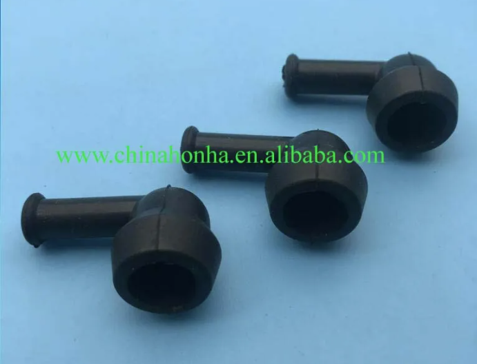
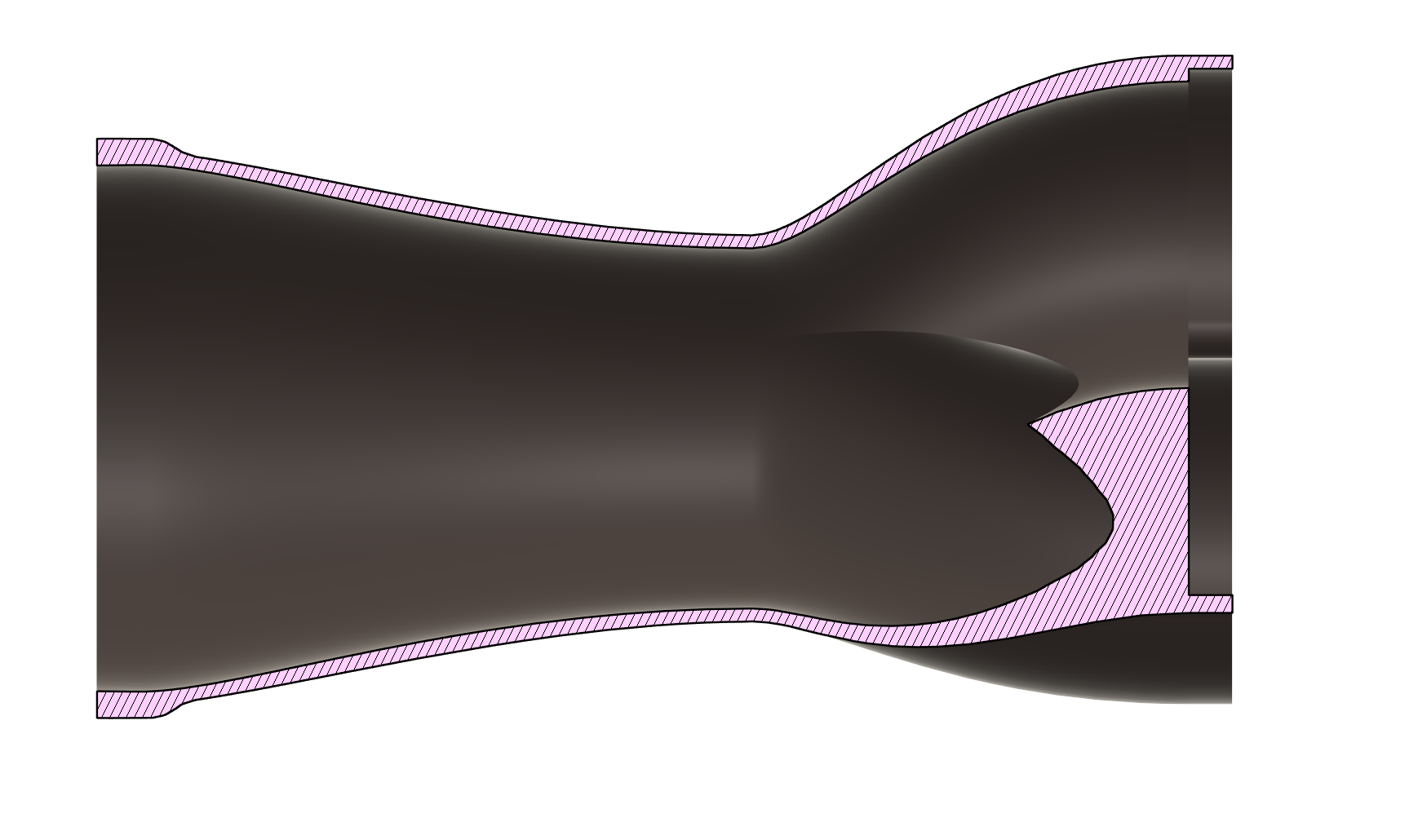
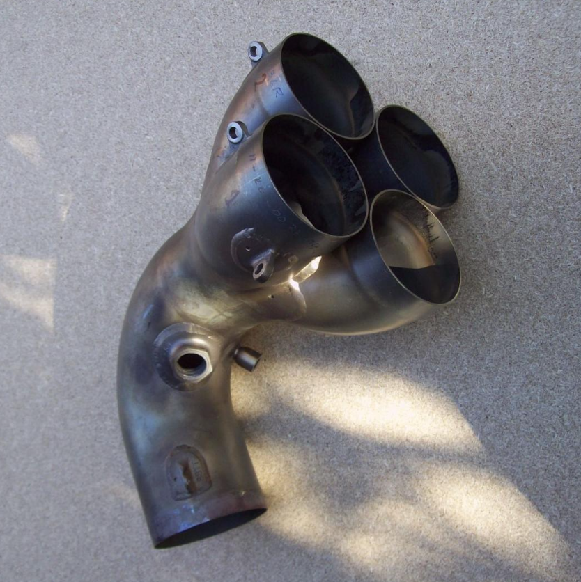
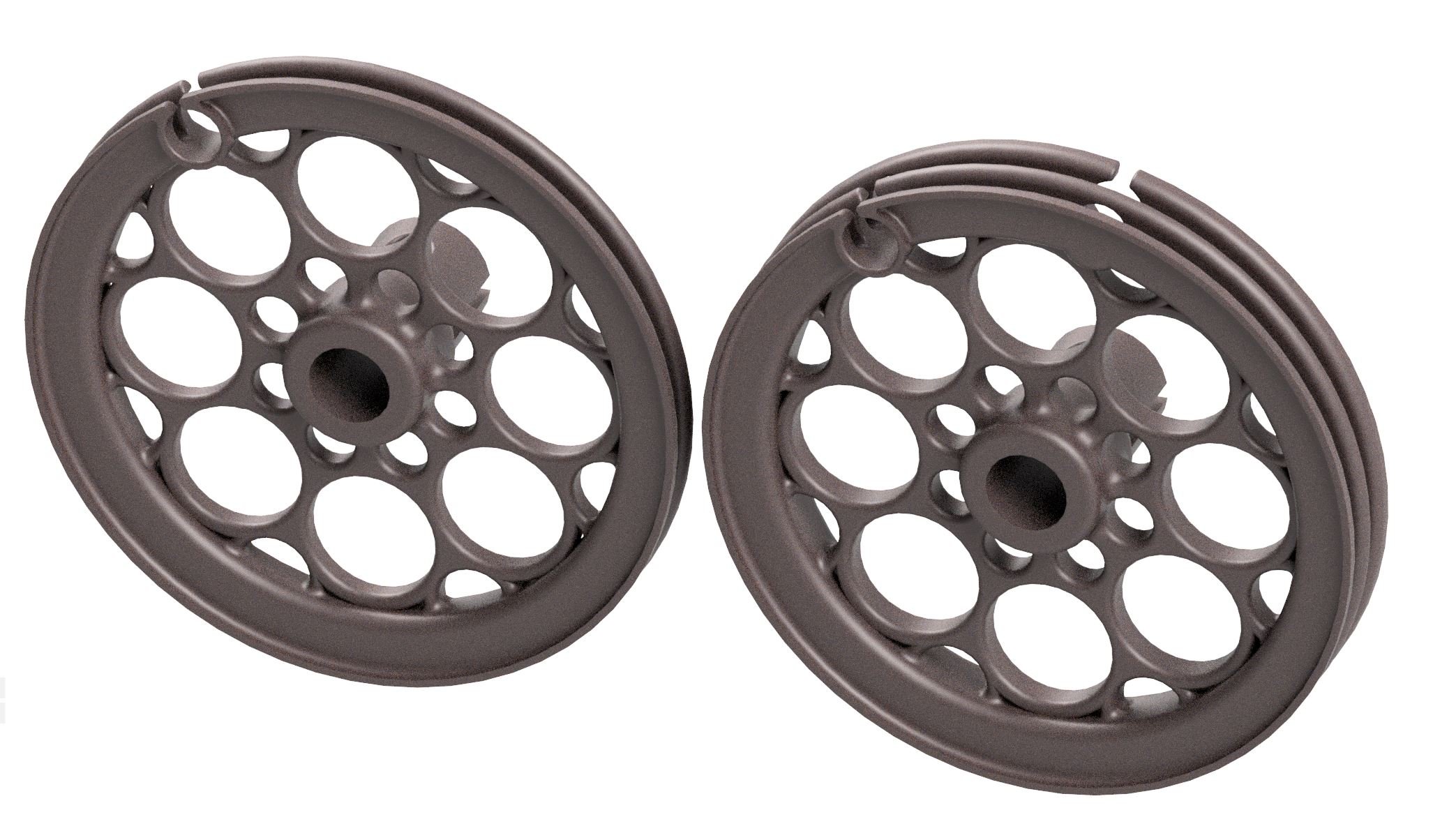
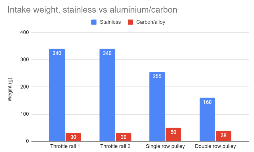
I havent had any time or space to get any welding done on the exhaust, but I've nearly finished putting the rest of the motor all together. But once thats finished I can push the car back outside for a few days and have some space for doing stuff again. Having a V6 with 3x timing chains really makes me appreciate how much simpler life is when you use a belt, and can just take the timing covers off without 3 litres of RTV to deal with. Exhaust collector side quest I've been doing some more reading and mulling over collector shapes/options, drew up shape that I'm happy with and have put through an order. Just one for now, in case it's crap. Estimated 7-10 days arrival, $263 delivered. Seems insane! Hopefully it works out good. I've opted for having quite a tight choke point and quite a short merge. Which makes for a fairly steep angle. But when you arent fabricating it out of just straight sections of pipe, I think the shape should still flow pretty good. I think some of the general rules around collector design are based around 4-1 construction and only having straight pipes to fabricate things with. When you have a 3-1 without the symmetry of a 4-1 or 2-1, it seems like making the merge section longer doesnt affect the shape of the center part by much. So I'd rather just get the change in cross sectional area over and done with, then start tapering back out which I think is probably the more important bit. This is using 3x 38mm OD pipes for the runners, 1.75" choke point and is a 2.5" exit. So can taper this out further to 3" or maybe keep the 2-1 section as 2.5". Not sure yet. While looking at different cars collector designs it was really interesting to see that F1 cars seem to have some fairly gross looking merge designs, like this weird 3:1 Or the crazily steep merge angle on half of a V8 Some of it looks like packaging determines the shape more than anything, so I'm not too concerned about the (hand waving gestures) manner in which I've made the shape of these ones. While I'm drunk on the idea of metal 3d printing Aluminium is even cheaper than stainless to 3d print, so decided to price up making some better throttle pulleys. As they ended up being surprisingly heavy with the stacks of 2.5mm stainless, and they look a bit shoddy. It would also be nice to have more of an internal radius for how the cable sits. So now the design is much, much lighter. To print from aluminium the single row pulley cost $32 NZD, and the double row pulley cost $40 NZD. But then shipping was $50, this seemed to be the same price regardless of whether it was 1 or 2 pulleys. So next time if I've got a bunch of small brackets etc to do I'll make sure to put all the files together at once. Hopefully they turn out good. I dont know how much detail the metal printing is actually capable of. A week or 3 ago I also ordered 2x 500mm lengths of 10mm OD carbon fibre rod, which is something else that is surprisingly cheap. So I'll use this instead of the stainless steel rods to link the throttles, as these are also surprisingly heavy. The weight difference is pretty incredible, will be going from ~1.1kg down to ~140 grams.
- 131 replies
-
- 31
-
-
-
Daves new school holden shambles. (Is this project oldschool yet?)
Roman replied to Muncie's topic in Other Projects
I think the best thing with the wheels is just going to be cut your losses, sell on and buy something that better fits. It looks like it's going to be mega mexico spec which is pretty hard to rectify. Especially given the rear guard shape is formed by the bumper, rear quarter and the door. If you have to pull the guard out a significant distance you'll need to get the door and bumper sort of cooperating or it'll look like ass. Then getting all 3 elements to work together is HEAPS of work to make it look convincing. But if you could get those flares from the adventura or whatever it was called, could look good if thats a bolt on option. If you can fit 275s with a wheel that has more positive offset and fits under standard guards its going to look incredible. Sorry for haterade, I love your work but I'd hate to see a guard roll make a mess of things and not achieve what you want. It's a really hard part of the car to repair if you want to walk it back. -
Daves new school holden shambles. (Is this project oldschool yet?)
Roman replied to Muncie's topic in Other Projects
Man I hate people that gatekeep shit like that. Like, if your entire career revolves around hiding some basic knowledge that is so simple that anyone can do it. Then you're shit. I figure there's no reason not to share knowledge - If someone copies you, you then the best they can ever be is as good as you were yesterday. Anyway, I wouldnt hold your breath for a ride along tuning the Dave6 as it seems like I keep getting roadblocks at the moment. However yeah I'm happy to catch up sometime and go through the software together and try make some sense of it. Some of the tables probably arent very intuitive initially, if they have an axis that spans in grams per second or whatever. But it makes sense once you get your head around it. Does the car run a MAF or is it MAP based? Flick me a PM if you want to get sharned into oblivion about ECUs some time.