Roman
-
Posts
7,233 -
Joined
-
Last visited
-
Days Won
39
Content Type
Forums
Downloads
Events
Gallery
Everything posted by Roman
-
@dabuzz are you sure that everything on the car gets recerted? My understanding is that if you've got an existing cert, but then change just one thing, they effectively recert for just that. Any clarification on this one please @cletus
-
Looks friggen awesome.
-
Hah, cool! Developed in early 80s so almost period correct for some idiot to throw into a mid sized coupe https://en.wikipedia.org/wiki/Yamaha_OX66_engine Amazing power given the crappy injection and distributors etc. Amazing power for displacement.
-
Unless you had the filter plumbed up backwards, wouldnt it be doing nothing? As its just an anti drain back type thing?
-
Ages ago a mate bought a JZA70 Supra, it was a good price, the right model, etc etc etc.... And it had this absolutely massive air brushed Conan the Barbarian on the bonnet. It was incredible, and we mocked him mercilessly well past the point of repainting the bonnet. In hindsight, what a bunch of cultureless savages we were to not appreciate the art work. For shame! I absolutely cannot wait to see some air brushing on the panel van.
-
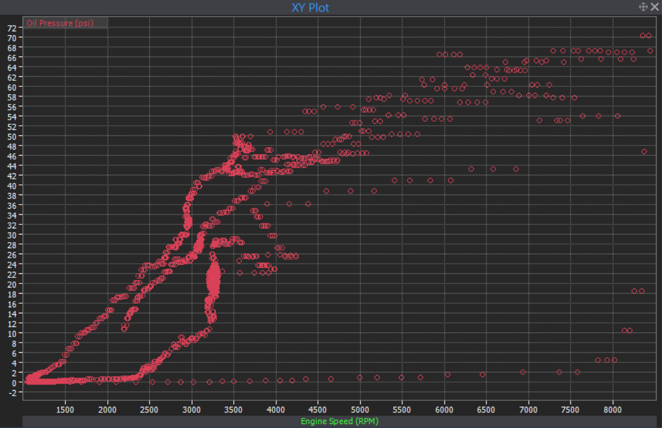
That's a weird one, if it's easy to get the oil pump off, perhaps could try shimming the spring on the relief valve and see if it makes a difference? This is the sort of oil pressure spread I get with V6 motor (just before it shit itself, one of the times it shit itself) Dont get 30psi until around 3000rpm, dont get to 60psi till 6000ish so I'm not sure if you'd see this problem (or not problem) become evident by running the motor and idling it.

-

Discuss here about Yoeddynz's little Imp project...
Roman replied to yoeddynz's topic in Project Discussion
This might sound crazy but there isnt something like a lego character stuck in there? -
Discuss here about Yoeddynz's little Imp project...
Roman replied to yoeddynz's topic in Project Discussion
Does a flat six actually have any reason to sound different than a straight six? As in, arent they both even firing order? Wonder if the "flat six sound" is more "air cooled sound" -
Hello darkness my old friend (entropy)
-
I think black holes form in the universe, when someone figures out you can connect an alternator up to the wheel, that then feeds its power back to an electric motor that spins the wheel
-
Your car has a way bigger engine and an equally big turbo hanging off it. I think the only way you'll be seeing my tail lights, is if you're parked behind me when it's blown to smithereens. I'll be absolutely over the moon to just get the car down the end of the strip to be honest. I'm not sure if I'll be able to fit the big cams in by December as there's possibly still a few curveballs to contend with. I think drag racing is one of the few things where sometimes it feels like you're missing out when you're participating. Because when you're lining up you dont get to watch all of the other cars run. Super keen to see yours there! God I cant wait to get to the point where I can hoon nightspeed events and do some track days again. I'm only about 35 minutes away from Hampton Downs now, and about 40 to Meremere.
-
This month's car budget activities: -Ordered extra pipe for manifold as I've run out of long enough straights. -Ordered wideband bungs. -2nd wideband controller ordered so I can monitor each bank. -2nd Collector is still being manufactured, hopefully here soonish. My weekends and evenings have been busy making stuff for goats over the last few weeks, but I think I'm still on a good timeline to get to drags. I've been going back and forth between dreading moving the alternator, and dreading making an equalish length manifold where I cant have U bends in it. However I had a bit of a breakthrough. I realized that my 90 degree bends are a much tighter turn than the 180s that I was using on the other side. This means all of the pipes can still go as far forward as they like under the alternator, and there's still plenty of room. So I've copied the dimensions of the bends and length of stuff back into the computer to get an idea of what to do with the 2nd and 3rd runner to get them fitting okay and about equal. Once again with a 180 degree bend in the shape makes it a piece of cake compared to having to rejig the angle of every single part to adjust it. It looks like this should all fit up and as it sits those are within 5mm length of each other. If some pipes turn up tomorrow (probably not) will hopefully make some progress over the weekend. But it feels good to have a workable plan now. Might cause some other issues but these are future Dave's problem
- 131 replies
-
- 39
-

-

-

-
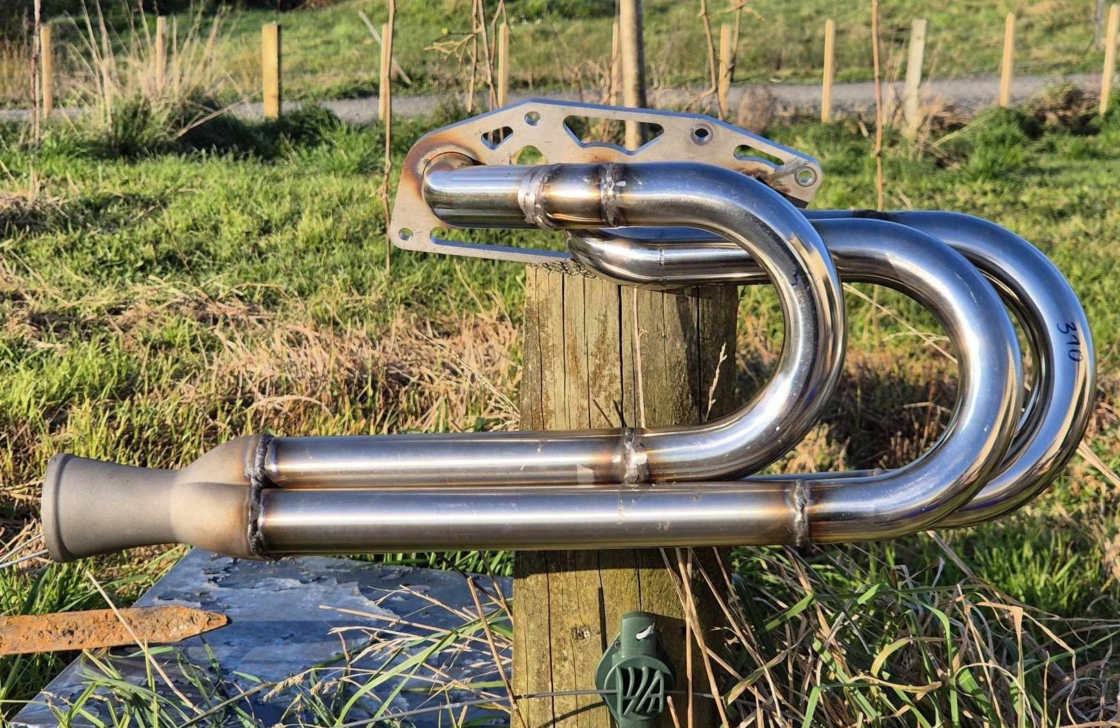
New exhaust sounds legit! Excited to see this back up and running again, so much cool South Island stuff to do. Reckon you'll run it up Coronet Peak?
-
Must feel nice to ask someone else that for a change
-
Will require some sort of positioning signal, as otherwise it doenst know the frequency of firing injectors. However are you wanting to use one for something else? You could probably put it into a test mode or generate a fake signal easy enough.
-
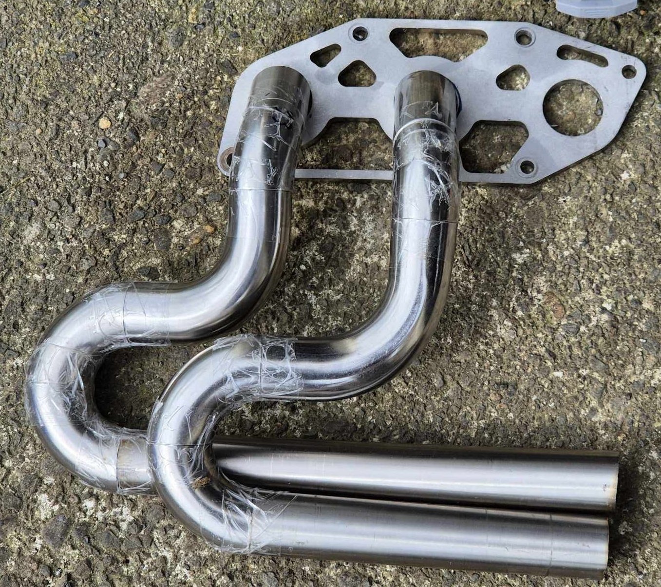
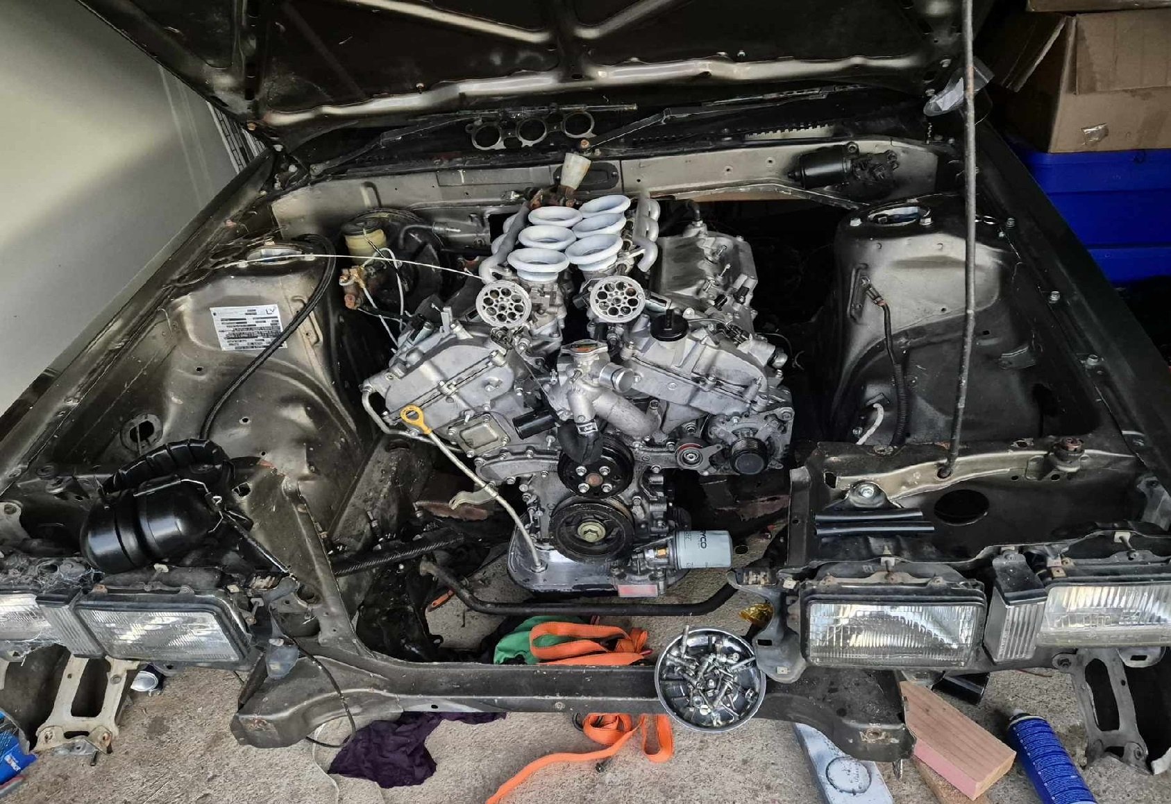
For now I think I'll just leave the alternator where it is and work around it. Relocating alternator can maybe be a future-Dave scope creep activity. Once I've got a 2nd engine and some garage space I'll do some scheming. Looking at my manifold on the drivers side, I keep wondering if it's long enough... seems short. Think it's something like 980mm per runner, give or take. But then looking at how far back I'd have to run the manifold on this side if they go straight back, it's huge haha. What I'm currently thinking is that I'll try take up as much space as possible still in the engine bay by running the first pipe as far foward and down as I can. Then the second pipe can sit on top, so the third pipe can extend out further so it can run past the other two to make up the length. But I've run out of straight sections so will need to order some more. Bend #2 might need to get a bit wiggly to get enough length in it.
-
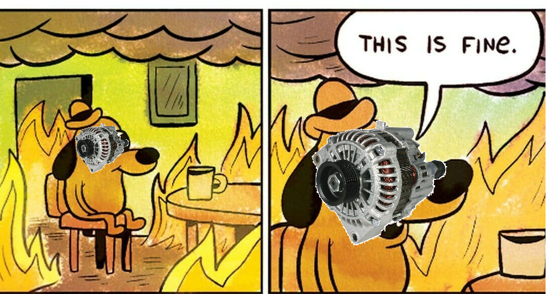
@h4nd Seems like a belt slip nightmare. Same belt has to run the waterpump, so not keen on any risks. Will just make the manifold work around it. As per the Echo having your day ended because of alternator or waterpump problems is a whole bunch of no fun.
-
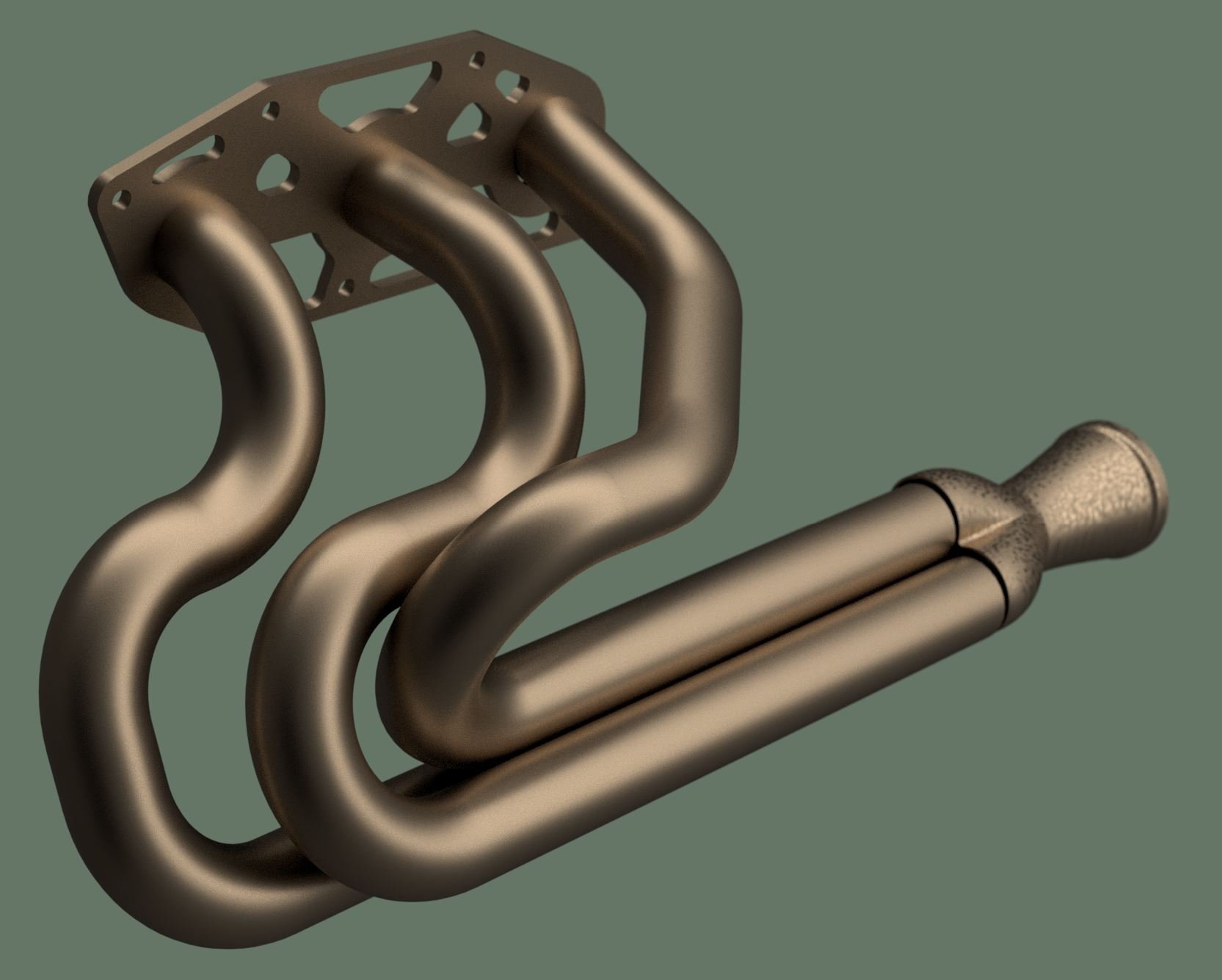
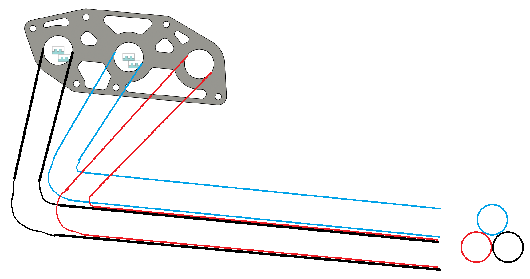
Sorry for bit a of a punishing non-update, been a bit spammy lately and no cool stuff happening. However it's exciting to feel like I'm close to getting the motor going again. I got all of the timing cover and sump back on, which honestly takes hours to do. So much gasket goo to scrape off and reapply! And find all of the right bolts gain, ha. Then I managed to get my drivers side manifold all welded up properly. Some pooey welds but seems strong and doesnt leak so calling it a win. I ended up completely redoing the 2nd runner, as I burned a hole that I ended up chasing around the place. Just seemed to get worse and worse! So restarted with fresh bits and it went together a lot easier. Maybe there was still some oil on the inside of the pipe or something. But the 3d printed part welded up fine, it was easier than welding the pipes. Super happy with the decision to print the collector. I might add some extra bracing to hold the three pipes together before they start diverging. The flange is welded on from the back, so it should be really strong. As it's not hanging the pipes just from the weld. The tight fit of the flange can hang the weight no problem. My scheme of welding a little triangle bit on the inside between the pipes, then just welding full around the outside looks to have worked well. Hopefully no leaks and no breakages! Should look good once it starts getting some colour into it once it's heated up. However I will likely heat wrap them anyway once I've confirmed there's no leaks. I've been thinking about moving the alternator somewhere else, so I could have the same design manifold on both sides. But there really is nowhere else to put it, even if I flip it around so it's mounted backwards somehow. Not quite sure how that side is going to work yet. But here's an artist's concept drawing of how my manifolds might end up looking:
- 131 replies
-
- 45
-
-
-
-
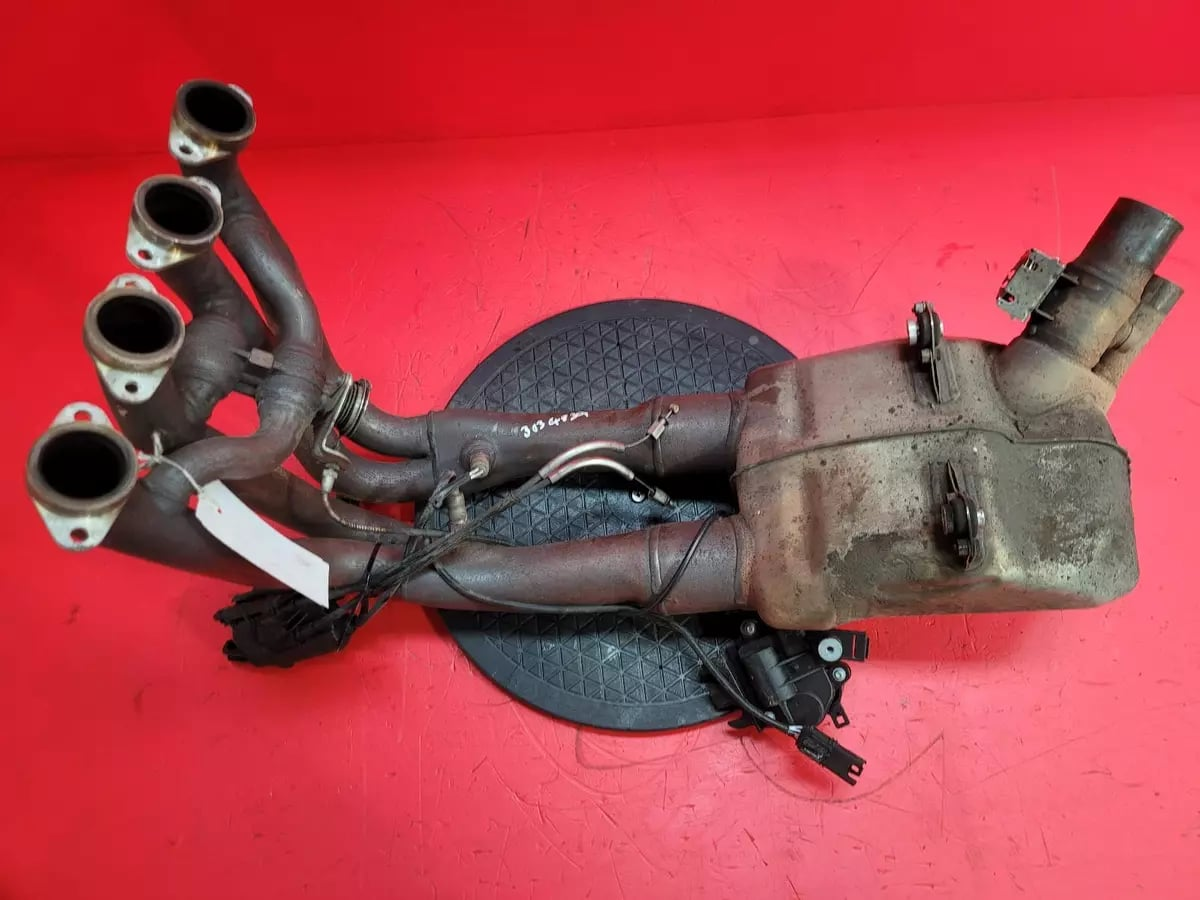
Ahh yeah! HKS does quite a few with that design: Something else interesting that HKS does, is they make 4-1 manifold for the Altezza that links the pipes together into pairs. Not sure if this is some sort of tuned length thing, perhaps it makes it behave more like a 4-2-1. But interestingly it's linking the cylinders which are not 360 degree separated. (should be 1&4 and 2&3 if evenly spaced) Then even further off topic, but the S1000RR bike has exhaust valves that open or close based on rpm, that link pairs of cyls together. It seems that HKS is the biggest mainstream sort of company that has experimented with this kind of stuff. Might be interesting to have a dig through their back catalogue. Seems the "HKS hi power" ones usually have that design.
-
Those pistons turned out so cool. Cant wait to see how this goes!
-
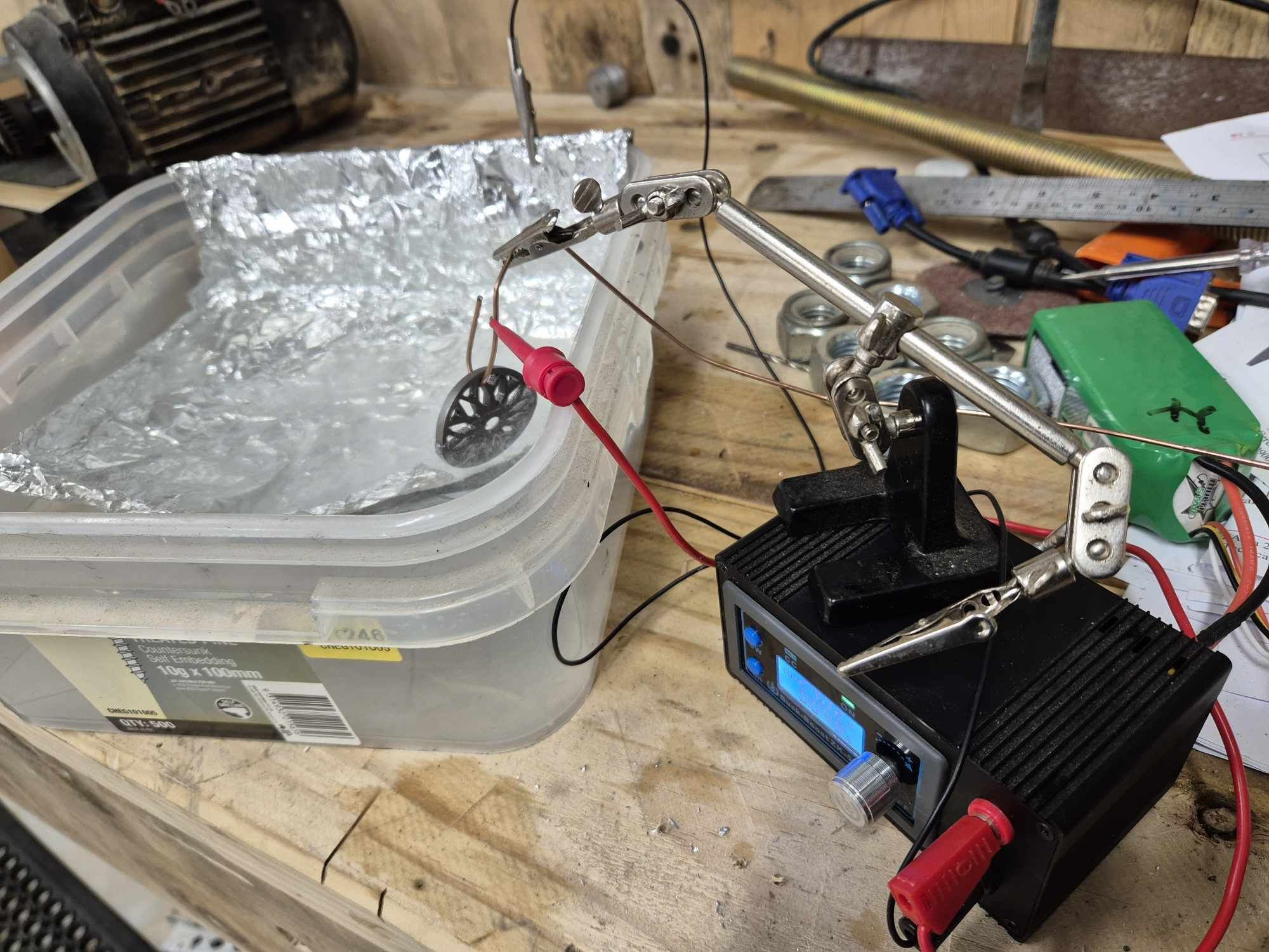
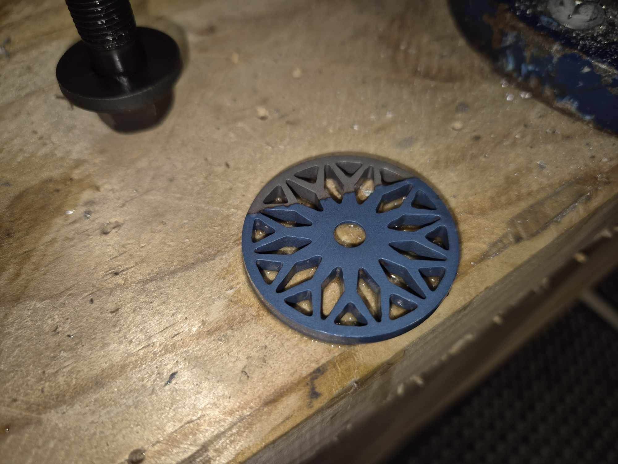
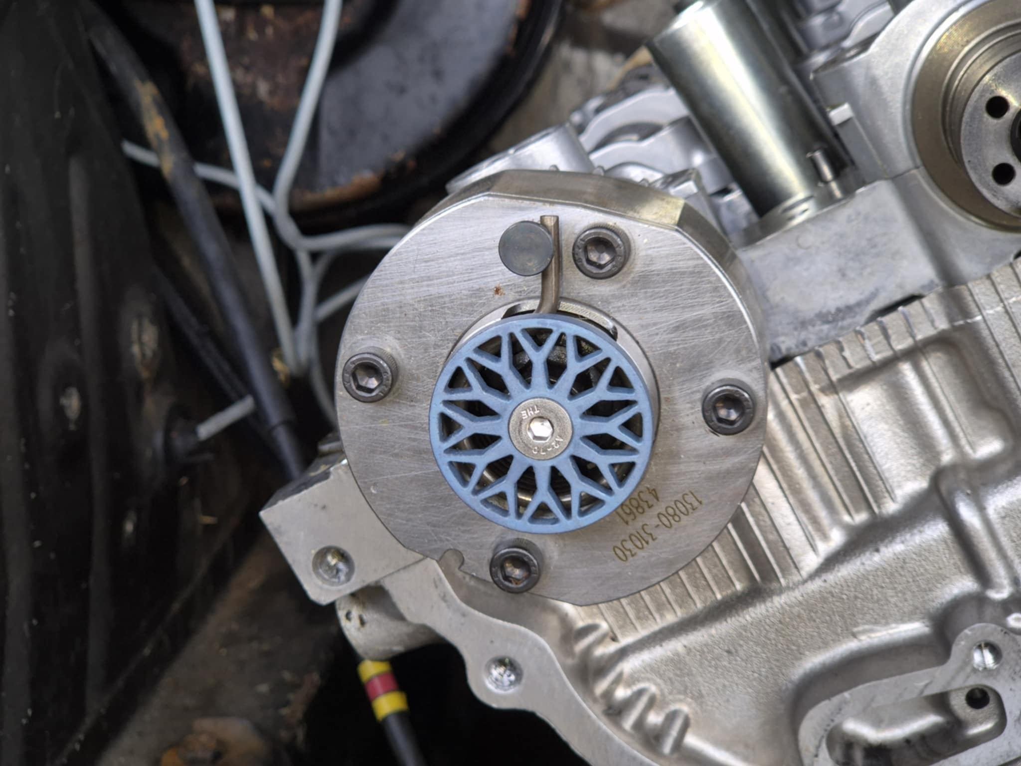
VVT pulleys So the titanium cover plate things turned up, and they looked really good. @flyingbrick helped me drill and tap some holes in the cam pulley bolts so they could fit on. While we were there, he was talking about how you can change colour of titanium just by applying voltage through it. Different voltage ends up a different colour which is cool. So we gave it a go. Initially it didnt work too well. possibly because the part was bead blasted or something. But quick acid dip then it coloured up good. Then everything's fitting up good, so motor is ready to go back together. Cant do much at the moment though, as it's too windy and rainy. But next block of good weather and I'll hopefully have the timing done and maybe the sump back on. I've also fitted grade 12 cap screws into all of the pulleys, with the strongest possible loctite. Hopefully that's the last of my VVT troubles.
- 131 replies
-
- 43
-
-
Yeah agree. Im sure there is many an engine that has gone boom when the water ran out. Just another cause of engine anxiety!
-
Yeah 100% A lot of the vitz bolt on supercharger kits are non intercooled, and a similar design to SCs I think... they run so damn hot that they end up making about the same power as a standard motor haha. They absolutely fly once a water meth setup is added, but it's a whole lot nicer and easier to just have a good intercooler on it.
-
Yeah stuff like that is perfect use for it. You should check out what Matt Gill has been up to, he's been seeing how far he can push the SC12 and SC14. His SC14 setup ran a 13.6 at the drags on a 195 street tyre which is awesome! Must be making some good power, think he said he ran a 105 or 106mph over the line when the car was colder. I've always shit talked SC12/14 setups but he's making it work really well. https://www.instagram.com/garagedori_nz/
-
I dont think its a case that there is still oxygen present by the time the air/fuel comes past the sensor. So much as that a motor never capitalizes on 100% of the expansion energy from the gas. Which starts expanding once it's ignited, but doesnt stop expanding until well after it's left the engine. Like if you took a 500cc combustion chamber's worth of air and fuel. When you combust it, the air and fuel wants to expand to a size of say... 3 square meters (or whatever) So to use all of that energy you'd need something like a 10 meter long stroke length. So thats part of why even if your ignition timing is optimized, exhaust gas still comes out with lots of energy and is hot loud and chaotic. When you retard the timing you're pushing the expansion curve further out the arse end of the engine. In terms of ignition timing, and part throttle. The more densely packed the cylinder is, the less time it takes for the air/fuel mix to ignite from one molecule to the next. So to get the peak pressure happening at the correct time (about 14 deg ATDC) you need less ignition advance when the cylinder is fuller. As you reduce the amount of air and fuel in the cylinder, by closing the throttle a bit more. You need to increase the timing to account for that it burns slower and expands slower. So just try think about it that way, best ignition timing is always just to get the strongest pressure happening after TDC - You only ever ignite the fuel before TDC because it takes so long to start expanding. Getting the part throttle tuning right is absolutely critical for the crisp throttle response. With e-throttle it's easy, as you can just set it so that 100% pedal is only 80% throttle, and do some runs exactly the same each time and dial it in. However it might be useful to make some mechanical stoppers for your pedal or throttles so that you can get some repeatable results for tuning part throttle. When I had the echo setup with lots of repeat runs on part throttle, it was insane how much more punchy the car was on transient conditions. I would be looking to optimize ignition, fuel, and cam timing everywhere you can for what gives the best power. Then if you do feel like trimming the power back out of it, I'd keep the VVT at or close to it's full throttle angle, because there is some mechanical latency. But then just trim some power back out by pulling the ignition timing out a little. But I doubt you'd need or want to do that.