yoeddynz
-
Posts
17484 -
Joined
-
Last visited
-
Days Won
134
Everything posted by yoeddynz
-
I've only ever killed one sensor, a 4.2, which was coupled to a Inovate mtxl. I think I know why though- thermal shock from having the ignition on for a while, the sensor heating up and then starting the engine is what I suspect killed it. Anyway- not going to touch their products again. I think with a newer controller from Aem or 14/7 I wont have these issues. I don't think I need to stump up the extra pingas for a adv sensor though. Not on a 100 bhp NA engine that's not really going to see silly revs/will be more of a road cruiser. Anyway - 14 point 7. Fuck me he seems a bit useless at communication. Doesn't fill me with confidence. I'm glad to hear he stands by his products because it does seem from other forum posts a fair few of them have issues. But then you'll always hear about the faults first. Reading the above forum thread is interesting too. I'd love to have seen him come to the party and just swap units with AEM fella so they can test each others rather than him just having a sulk. Interesting to see that his latest units now have a response time of 10-20ms depending on the sensor - a time he had been harping on was impossible and the AEM were manipulating their results Either way, whatever unit I end up with - be it an X series or a S3, it'll be streets ahead of the old Inovate mtxl/4.2 combo.
-
I'm still trying to decide on which wideband setup to get. Its either going to be a 14 point 7 spartan 3 or an AEM x series. Both offer CANbus for a nice clean accurate and fast signal that I might as well go for. Anyway in searching for info/tests/comparisons I found this old thread that spans a few years on freds diyefi forum. Its all about wideband controllers and gets quite nice and nerdy. Skip the first load of pages and head straight to page 16 which, in 2015, is just after AEM released their x series. Make some popcorn and read the entertaining cat fight between DelSolid who works for AEM in California and toalan, the Canadian behind 14 point 7. http://forum.diyefi.org/viewtopic.php?f=6&t=2267&start=150 I've not yet finished reading it all. But its getting heated
-

Yoeddynzs 1965 Hillman imp + Honda flat six. Datto out.
yoeddynz replied to yoeddynz's topic in Projects and Build Ups
These bits turned up thanks to @Corbie .. Sweet. I've got some coils and a spare ignitor. but hang on a minute... something ain't quite right. One of these things is not like the other... This will give me nightmares if I fit a mismatched coil. I'll have to look about for another matching FC0021 While is was looking at ignition stuff I dug out the original Goldwing coils and leads from the store room. Then this happened to them... The leads have molded rubber boots, shaped neatly to seal the spark plug holes. Three of them are perfect for the LH bank and will point the leads nicely towards the front of the car direction. At this point in time I am planning on mounting the coils up under the parcel shelf, sort of above the transmission and out of immediate view. But the other 3 boots left over are all over the place. Only one remotely points towards the transmission. The standard leads are solid copper strands and from what I know they are not the best thing to have around electronic engine management. Maybe they are OK? I'm not 100% sure yet but what I do know is that they were too short and a bit messy looking. At the spark plug end there's a very neat little brass fitting that screws into a plastic guide inside the boot. See the bits here... The tread is m10 x 1.25. How handy. I'll get a long bolt, screw it in place, clamp the bolt head firmly in the vice and simply pull the rubber boot off the plastic insert... Poos. I superglued it back together and put it out of sight. It'll be fine. I think I can pass 7mm silicone leads through the insert anyway when I make new leads. I don't like the way the silly boots that refuse to point the correct way bend awkwardly. This is the best of them. Not really neat enough and I only have the one of this shape anyway. So I got a sharp knife and performed a little circumcision on one of the 2 remaining... The end tapered nicely with a flapdisc on the grinder... And looks OK in place. If I get some nice flexible leads they'll curve the way I want fine I think. Now the fuel rail fittings. I had a certain look in mind, tidy, simple and pointing the hoses where I wanted them. I machined up these bits in stainless. You can see the first one I had made and brazed already just as a trial.. silver soldered them together. Not as neat as I wanted- possibly it doesn't flow so nicely on stainless? Luckily the worse bits face down. Now to get the angles just right and mark them.. Then braze them in place... I'll clean them up in the morning. My plan is to paint the rails in black epoxy and leave the stainless bits clear. Hopefully they'll be tidy enough for this to work out well. The rear inlet I have yet to decide on with regards the positioning of the hose. I'm leaning towards it heading down out of the way rather than across because I'd like to keep the area around the throttle body as clear as possible. For the fuel pressure regulator outlet end on the other rail I had to first turn the end of the reg mount down. Awkward in the 4 jaw so I mounted it to a lump of alloy that I'd turned a spigot onto, so centralising the mount. Regulator can now mount here... But it just annoys me a bit that its sitting there, right over a plug hole, on view. Luckily the home made spark plug wrench I'd made... ....because I didn't have one to suit the plugs/hole size on this engine when I was stripping it down, still fits and works but would be better with a smaller diameter shank.. But maybe I extend the rail with a bit of curved tube and mount the regulator sort of here... I shall ponder this and look at it tomorrow. Time to kick up my feet and do my next bit of google homework - look up leads for the ignition.- 99 replies
-
- 48
-

-

-
Yoeddynzs 1965 Hillman imp + Honda flat six. Datto out.
yoeddynz replied to yoeddynz's topic in Projects and Build Ups
Cam phase wheel continued. I needed a nice solid accurate hub to mount it on for machining the slots. Found a suitable chunk on the rack and turned it down to suit.. Drilled and tapped a hole in the middle then machined a solid cap which is pulled down tight so holding the disc in place.. Using the cam pulley as a template I scribed the outlines of the slots in place. Then into the mill and made lots of mess. Because I don't (yet) have a rotating table for the mill the slots are straight, not curved. But being short in length and even they look ok. Good enough to knock a little weight off. I'll leave the final machining until just before assembly in case something changes with the sensor although I think that's pretty much sorted as I have a brand new sensor as used in many Peugeot/Citreon/fiats plus the ever helpful @chris r had picked me up another one plus some various plugs I needed from pick-a-part. I have been accumulating various plugs and terminals from Aliexpress in my quest to be able to make a new engine loom without having to splice wires to connector pigtails. This arrived in the mail from friendly @fletch, gifted to the cause Its a genuine Mitsubishi ignitor for a Mitsi GTO/many other Mitsi V6 vehicles. However - its the one item I have been struggling to find the correct terminals for. They are either Yakazi or Sumitomo but I've still not found an exact match. I'll keep searching but luckily mr @Corbie is gifting me an ignition module, exact match, plus the 3 Mitsubishi twin post coils with the leads/plugs intact between the coils and ignitor which will make for less splicing. Another little job I checked off was to make some blanking plugs for the unused air injection ports. Not sure if they'll get painted over or left as bare alloy yet. In place but not yet fixed in. Much better than what was there (look back a post or two) Back to cooling pipes then. The extra 22mm bends I'd ordered had arrived so I could continue on with the top pipes. I found another bit of stainless tube with a gentle bend set into it. Ideal for this area... I used some of Dads old surgical forceps to hold the pipes in place while I tacked them.. Now I needed to merge the pipes into a larger size so off to the press.. Tacked in place and blend it in.. I joined the rear pipework with merger to the front pipe assembly with a short bit of radiator hose leftover from the front of the Goldwing. The rear pipe needed a bracket. Played with bits of card until I had a shape that worked.. copied it into stainless like such.. That was welded in place and the top pipe assemblies were pretty much finished. You can see how they are routed in relation to the inlet manifold once its back in place. As with many aspects of the build so far I have done my best to make sure they can be easily removed and don't hinder the removal of the inlet in one piece. I'll be adding to their length, plus the bottom pipe , once I have worked out the best positioning of the water pump but that has to wait until the engine in the back of the spare imp for mocking purposes. Other trinkets/treats/goodies that have arrived in the mail are these universal joints.. They are for the gear shifter shaft that runs under the tunnel from the transmission to the gearstick. Because the selector rod enters the Subaru gearbox a bit higher up and at a slight angle compared to the imps original transmission I need these to connect the dots. I wanted something with no slop to keep the shifter travel tight. These have sealed bearings and are aluminium so lighter than they look. This afternoon I dropped Hannah off at Nelson airport as she's off to the UK to see her family. Almost 4 weeks home alone so I'll be trying to do as much as I can on this build While in Nelson I picked up another one of the same model chain that I'm using for the oil pump drive. I bought it mainly for with the special strong joining link that I needed. It wasn't looking promising to be able to get these particular links by themselves in NZ but no worries anyway as I'll need a new chain for one of my old bike restorations I'm in the process of doing so now I have one... When I got home I found this assembly in my mailbox courtesy of @dmulally. I now have a spare gearstick assembly so I can mock up and build the shifting linkage in the green Imp shell. Next step is to finish my fuel rail inlets/outlets to suit. Then a quick wire brush of the crankcase and assembly can start. With this in mind I searched deep into my moth ridden wallet and paid the man for some of this stuff which by all accounts is the best there is.. I'd like to give a big thanks to those who've helped out with parts!!! Bloody top blokes.- 99 replies
-
- 49
-
-
-
yeah this. I'll pick a sunny day and we can bumble along at a sedate pace alongside the lagoon and probably only ever see a tourist driving a tiida even slower then us.
-
I'll let you know what I find with regards the float heights when the van comes back in later this week or next.
-
Thread dredge - how's this car doing? Pics and vids please
-
Customer has a toymota passo that won't start. I've got to get out here for some work and wondering if I can tow it the flat 6km needed. It has a 4 speed auto so apparently no. But is that gospel? I always thought most things can be safely towed a few kms without damaging things.
-
It already looks lush but those trees are going to look cool when big. Very posh. You'll have to buy some nice old English car for the max photo ops. Plus the oil leaks can be used to kill the weeds.
-
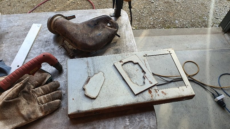
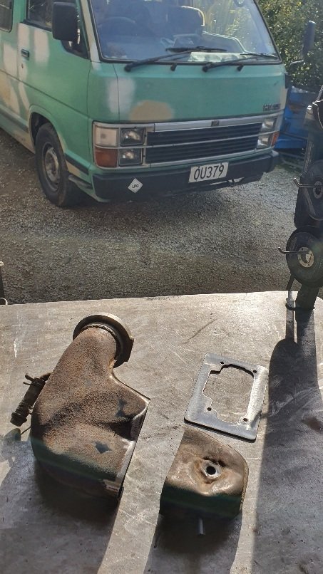
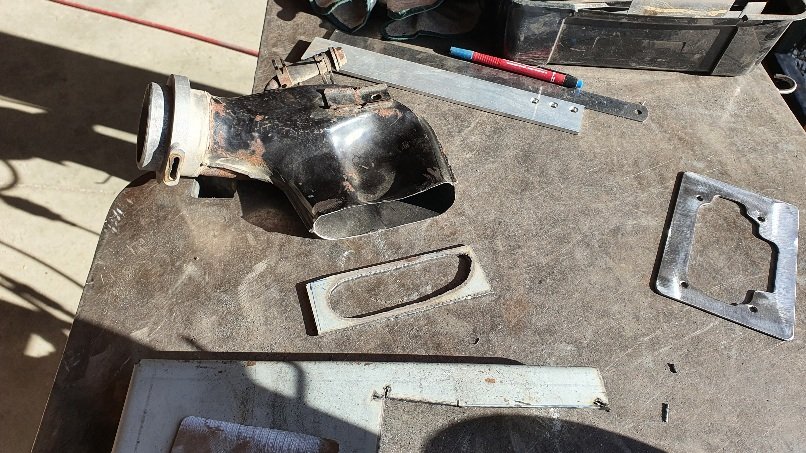
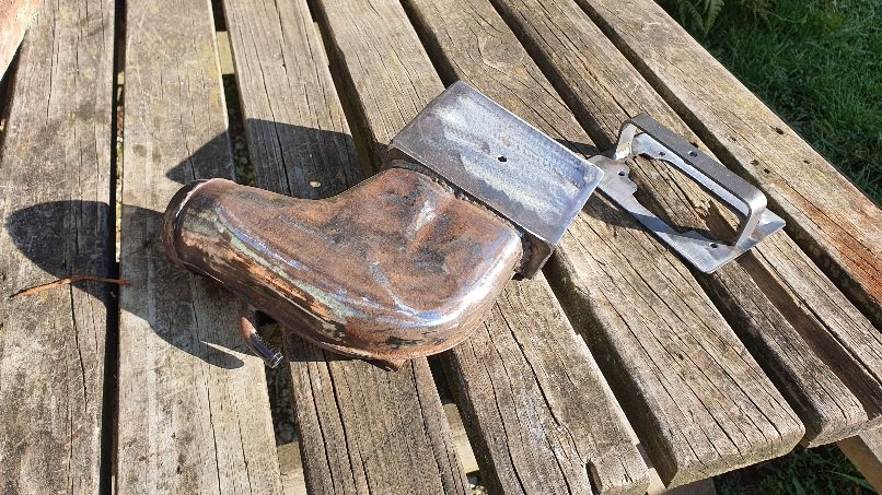
Ooooh that's small. This one I've made was 45mm tall, enough for the cross over bit of steel the centre bolt screws into clears the choke plates. It works fine but his carb smells, and it's running rich - suspect the float height is too high so probably prudent that you check the float height on your new carb is set right. I can't see how it's gone out though. Brand new carb and supposedly set up for the 3Y from the suppliers in oz.
-
I've just finished the steel carb hat/filter adaptor thingee. Waiting on paint to dry. It's basic and nothing to flash bit it'll work fine.

-
Nice one
-
I'm just super stoked to see that your back on here posting updates. Glad to see this project still moving
-
A few months ago I fitted the exact same carby setup and kit that you've got onto a 3y powered hiace. The kit came with a Ramflo filter (no less...) and although it works ok it lets through a lot of fumes and is slowly turning into a flammable time bomb. So the van is back in right now and I'm going to build a steel adaptor to suit the original low profile Toyota carb top hat. I'll report in with progress for ya. BTW- I had to mill/slot out two of the holes on the adaptor plate because it did not line up perfectly either. I made a manual choke cable using a bicycle cable that runs to a easy pull loop under the drivers seat.
-
So now your suit cases are going to get wet
-
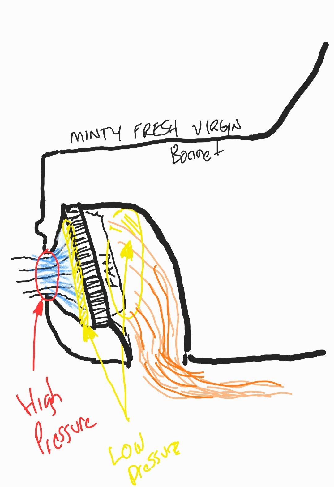
@Roman I hope you appreciate my stunning technical drawing...
-
please please please don't do what the lazy folk in the UK do and vent the radiator out the bonnet. Imo it ruins the clean lines and just looks a bit naff. Its very easy to cut a hole in the spare wheel well, brace it and make a nice bit of ducting to feed it out there I'm amazed at how well my setup cools that Datsun down -only a couple of times has the fan had to kick in and that was on stupidly hot days when stopping after a hot run. I think quite a bit of heat is lost just off the pipes heading to the front and back. Your small all alloy scooby motor wont take much to cool either. EDIT : I just read that you've already gone done punctured holes through your bonnet. Might as well add a scooby wrx bonnet vent, pointing backwards then. As for your front inlet- there's heaps of airflow through the opened up hole so just make a simple bit of ducting to spread that flow across the radiator face. You can angle the radiator too which helps as the airflow pulls more off the fins if it has change its angle as it flows through. No more holes!!! Naughty Damian. Bad boy! No pudding for you!
-
Discuss here about Yoeddynz's little Imp project...
yoeddynz replied to yoeddynz's topic in Project Discussion
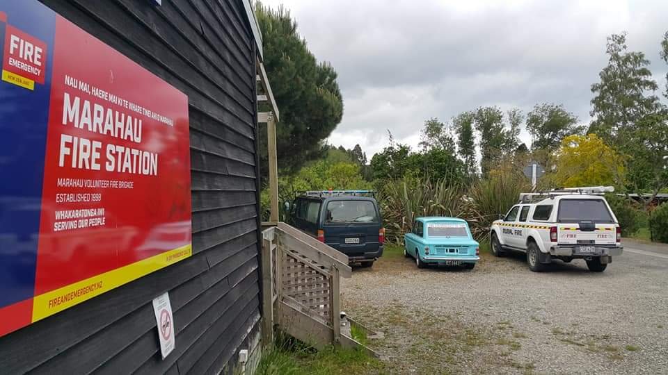
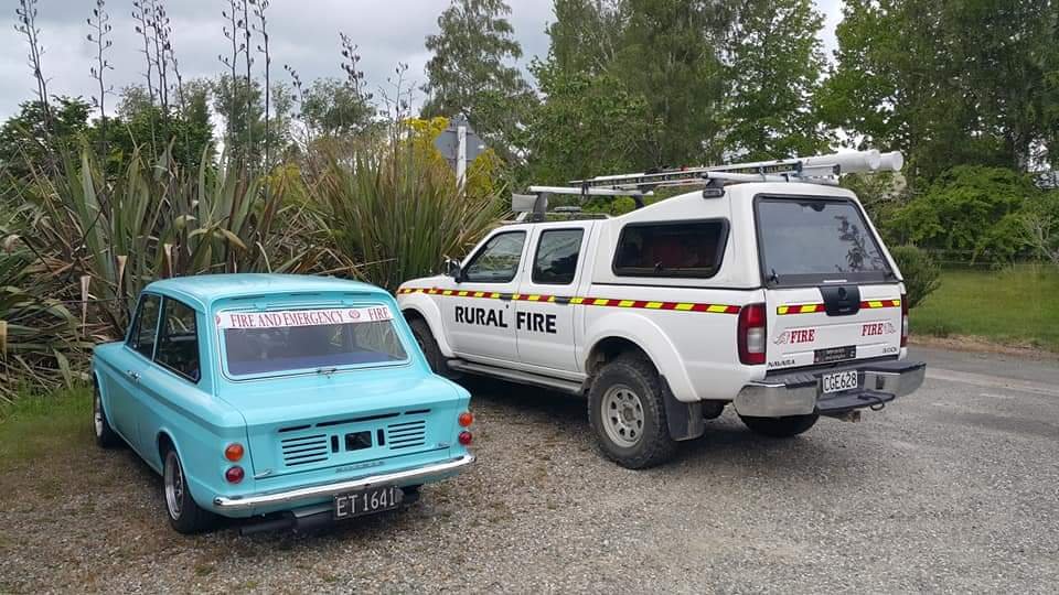
It's gonna be a proper hot summer for sure - perfect timing for the running in the new motor in the marahau fire station imp...
-
This is sooooooooooooooo much cooler than the mustang. Good life decisions. Ate you not tempted to it back change it back to manual?
-
Discuss here about Yoeddynz's little Imp project...
yoeddynz replied to yoeddynz's topic in Project Discussion
Thanks Dave. I'm glad you like the workshop photo. It took me 11 hours to carefully clean it all up before I took the pic. -
Can't ever remember them having a soldering station attached though? Yours must have come from a better specced car.
-
yeah that's them I think. They were mounted on a steel bracket iirc?
-
Thanks so much for the offer Stu but I think I'm sorted on the ignitor now. However- the info/ideas for ignitor possibilities is good stuff for future readers of this thread with similar needs. Heya cool- can you PM me a pic of the coils? They might be the same ones I had used in my Viva. I guess you had got them for your Maxi project?
-
Yoeddynzs 1965 Hillman imp + Honda flat six. Datto out.
yoeddynz replied to yoeddynz's topic in Projects and Build Ups
I'm still chipping away at the small jobs. Like most of NZ its been pretty wet outside recently which makes being stuck in the workshop even more cosy. I took this pic the other day. My cosy setup. Drilling and milling jobs are the warmest right now Hence I spent a bit of time staying warm and making some of the big chunks of alloy lighter where I can. Starting with the rear plate.. Then the sump plate... To aid the retention of the sealant I machined in some grooves between the bolt holes on both the plates. I'll be using good quality 3 bond sealant but everything helps. So apart from drilling and tapping a drain hole (suitable plug ordered) and making some anti-windage sheet metal bits the bottom end is finished. Oh I also lopped off the remaining unused original engine mounts - bit more weight lost Heat management time. To keep the cam cover seals from the radiant heat off the manifolds I needed some shields. I have had a basic design in my mind for ages but keep ignoring the fact it had to be done because not the most exciting job. First off was to make some brackets to mount the shields to. A bit of 1.5mm stainless and some marking out. drilling and shaping.. A fold.. Now I had to do a second fold to form a tight Z shape. But my folder won't allow such close folds and I really want these to be neat, one piece items. So I made a teeny tiny press brake. Milled a block of steel out... Milled a bit of plate to suit... Welded it to another bit of plate and welded a bit of pipe atop that and pressed away. (I really am super happy I built this press !! ) Now I had the tight folded Z shaped brackets I wanted.. Tidied up.. Fitted in place... I then cut some 0.9mm thick stainless shields to suit. I think I can go thinner. Not happy with the weight of them... Remembered I have had a bit of titanium sheet kicking about since I was a teenager - my sisters old airforce boyfriend obtained it from from the airbase and i was going to use it to make a cycle bottle cage or something - when titanium anything on a bike was super cool. But I never used it. Its lighter, but not by much and too small in size anyway. But now I'll just have to think of something silly I can utilise it on in this build - just for laughs/bragging rights So I'll probably get a bit of 0.5mm SS at some point for the shields. But for now I have at least got something to deflect the heat. They bolt to the brackets and will have some sort of heat resistant phenolic spacers to help prevent heat soak. Bolts were tigged in place.. Shield in place... Next up was the pipework as mentioned in the last post. I cut the old one up and carefully welded its shaped end to some stainless pipe. Not super pretty but happy as the OE pipe was less than a 1mm thick so it tested my skills. Then I started building the pipework in bits... I got as far as there and had to stop because not enough bends to complete the path I wanted the pipes to go in - I had used two bends for the exit from the other head. More bends are on their way from China as I type. Moving on to the next job I'd been putting off which was to make a half moon trigger/phase wheel for the cam angle sensor. I had already made a bracket to suit the Peugeot 307 hall sensor and knew the diameter I needed to start with. I rummaged about the steel racks and found a suitable piece of 3mm thick plate. Plasma cut a disc from it... Then into the lathe where it got a big hole sawed out from its middle. Much quicker than drilling and boring... Then bored out to final size - the process of which created a nice pretty lathe snake which came out of the lathes spindle... I carefully marked things out, drilled some holes and mounted the plate to the cam wheel. Note my lovely warm workshop/homeless person gloves. The bolts will be changed for countersunk items - the dome headed ones protruding just touched the reinforcing ribs within the cambelt cover.. The camcovers are well overbuilt and wont be in danger of getting hit in the back of a car like they could on a motorbike anyway so in an effort to make sure there's plenty of clearance I milled the ribs down.. I'll mill the slots out to suit on the trigger wheel and will add the remaining bolts (just in case 3 wasn't enough). It'll have half of its circumference machined down, with a corresponding amount in weight removed from the other side just to make some sort of effort to keep it fairly balanced. I bench tested the Peugeot sensor I had picked up from the wreckers - its a dud. Probably what sent the car to the graveyard considering the prices that the local NZ suppliers want for them. A new one is on its way from overseas. I have also ordered quite a few other little bits. New terminals for my injector plugs and a crimping tool. I'll be ordering other terminals to suit the various plugs that will be adorning the engines injection and ignition system. I want to create a loom without any unnecessary extra joints. I have never used a proper crimping tool as such. I got a set of little stainless tools for dismantling various connectors. Already used them and quite a breeze compared to my old screwdrivers, nails, pliers methods. I need to suss out a suitable idle control valve. On the Mazda V6 engined Viva I gutted the original Mazda throttle body mounted ICV and machined up a nice little alloy housing to suit its PWM solenoid, so creating a remotely mounted ICV. I'd like to do the same but I don't have any Mazda TBs kicking about and there's also an abundance of cheaply available copies of Bosch remote ICVs available online (with good reviews) so I'll think some more about this bit. My ignition setup is coming along - big thanks to @fletch who is posting me a Mitsubishi GTO ignitor module. I'll most likely get a Mondeo/Jaguar v6 coilpack for the ignitor to..ignite.. So many different brands The sticker list on the side of the completed car will be long. 'This car has been brought to you courtesy of the following' .. Hillman cars Honda Goldwing motor Subaru transmission Honda civic clutch plate Subaru clutch disc Honda civic alternator Subaru starter motor Ford Mondeo clutch release Honda crx(?) throttle body (thanks Chris ) Nissan Micra injectors Mitsubishi ignitor Jaguar ignition coils KMC bmx oil pump chain Lego Mandolorian inlet manifold plenum guardians- 99 replies
-
- 60
-
-
-
@fletch that would be superb of you! Thanks so much. Would be perfectly ideal for a mitsi coil or one of the ford mundano V6 coil packs I have in mind. I didn't actually know these ignitor existed. Just did a quick search and found this info... https://www.stealth316.com/2-pwrtransunit.htm That mitis ignitor module has just what I need because it leaves the ecu to control dwell etc (which if my memory serves me right is about 3.6 ms for the mitsi gtslow coilpack I'd used in the Viva) I'll send you a PM

.jpg.2a077ed92f02d20f1f91266604c39a3b.jpg)