Hyperblade
-
Posts
337 -
Joined
-
Last visited
Everything posted by Hyperblade
-
Hyperblade's KP61R - Toyota Starlet with Honda K20a
Hyperblade replied to Hyperblade's topic in Projects and Build Ups
Some progress has been made. Driveshaft was sent up north to be balanced at a higher speed and the UJ's were tightened. And so had it out for another shakedown at a local sprint day. First race just took it easy checking things over (pretty boring video, best to skip). Second race, gave it full beans off the line against an EG civic with K24 and 300hp at the wheels, he got a bad start... Third race on slicks and it started drizzling, but overtook a Porsche and a Lotus... The driveshaft was a lot better, enough for me to push it a lot harder in those videos. But there was still a vibration there that won't be good for components, best guess is it's the angle of the engine/gearbox in the car, front of engine angled to left to clear headers and for weight distribution which means the UJ's are not in sync. Those videos also have me mucking around a lot with the brake bias as that's been all reset, along with suspension changes affecting rear of the car during braking so still getting it dialed in (sprint day you don't get many laps). Other thoughts, is the S2000 Gearbox throw is as short as the J160 with a short shift kit, if not shorter, it's a great feeling box. Also you may have noticed in my older videos I didn't heel and toe, originally that was because it was impossible to with the stock pedal setup and my seating position, but since I have the new pedal box and seat I really needed to learn, so with the minimal seat time I've been trying to get used to it, still a work in progress as you can see in the videos. So the shake down highlighted a few issues. Driveline Vibration still there What we believe is heat soak of the oil temp sensor as it hit 123 degrees, and there should be no way the oil hits that when it struggled to get over 80 on dyno (with some of my bonnet ducting removed which allowed a breeze over the sensor). Getting car up to temp with the EWP is a pain, it's not quite right at the moment. Was setup on dyno perfectly, but the real world has a lot more airflow over radiator. So before Christmas I shopped around for a driveshaft with a CV on the front, basically came down to only one place who were prepared/could make it to handle 9500rpm. Hence a new Carbon fibre driveshaft arrived last week from the Drive Shaft Shop out of the US, i'll be honest I was very hesitant in ordering from them as I had been forewarned by a couple of people about their quality and after sales support. But I had no other options. I can say their pre sales service was good with prompt communication and fast building of it and shipping. It still needs to be fitted into the car, we are just making up a flange that goes over the existing AE86 Diff flange (from the diff side) to better spread the load from the new driveshafts rear Hilux UJ which has a bigger bolt pattern. Here's the difference between Hilux and AE86 diff flanges. Heat soak of the oil temp sensor should hopefully be solved by some new shield i created. The EWP control is a bit if a pain, the duty cycle is controlled by RPM vs ECT. Which is great but i feel it misses another key input which is the speed of the car which affects the car's ability to get rid of heat. So it feels like half the solution to the problem. You can see the duty cycle all over the place here and the pump is barely breaking a sweat (and that's with half my radiator ducting closed off). For the EWP I made up (by hand, no lathe...) a reducer to drop the coolant pipe size down from 30mm to 18mm to slow the water, it goes into the return feed on the radiator after the water goes through the engine. I'm hoping that means I can use more duty cycle in the pump, so give a wider duty cycle range to play with. I've then tweaked the table handling the ewp to try and get it to be more flexible in it's ramp up/down by letting the ECU interpolate in between the cells more, feel free to let me know if this is a stupid idea... Old: New: So once diff flange is done, will aim to get it back out for another shakedown to see if we have finally solved the vibration and see how we are going with ECT. Discussion here:- 72 replies
-
- 10
-

-
Hyperblade's KP61R - Toyota Starlet with Honda K20a
Hyperblade replied to Hyperblade's topic in Projects and Build Ups
So what everyone has actually being waiting for, the final comparison between Toyota Altezza RS200 3SGE BEAMS and a Honda Accord Euro R K20a engine in the same chassis Still trying to get my hands on a single dyno sheet with the 2 different engines on it. So this will have to do. Modifications/Setup Toyota Altezza RS200 3SGE: 120,000 k's SQ Engineering Quad Throttle adapter plate 4AGE Blacktop throttles 70mm trumpets Combined Piper Cross Filter Stock Injectors SQ Engineering Slim line alternator (smaller Echo alternator) No Power Steering pump or AC Custom header (TRD Copy) to side exit exhaust 2.5" Adrenaline R muffler Link G4+ Storm (Blue) Engine internally stock Lightened flywheel HD Exedy Clutch J160 Gearbox 3" Driveshaft with sliding yoke into gearbox Oil: Castrol 5w40 Rev Limit: 8000rpm Dynoed in 5th gear 1:1. Honda Accord Euro R K20a: 108,000 k's Skunk 2 Ultra Street Intake Manifold 770cc FIC injectors Skunk 2 74mm Throttle Body. 3" intake pipe from pod filter. Custom header to side exit exhaust 2.5" Adrenaline R muffler Stock water pump replaced with EWP Alternator replaced with smaller Honda D15 one. No Power Steering pump or AC Stock Oil Pump and Balance Shafts replaced with ported Type S oil pump. New Timing chain Lightened flywheel HD Exedy Clutch Link G4X XtremeX Honda S2000 AP1 Gearbox 3" Driveshaft with sliding yoke built into shaft as gearbox has flange VTEC 4500rpm Oil: Castrol 5w40 Rev Limit: 9000rpm Dynoed in 5th Gear 1: 0.94076 Same: Tires 54cm Michelin Slicks at 21 PSI, on same Rims Same AE86 Diff (Brakes were changed from stock to AP with knock back) 4.5555 Crown wheel and Pinion. Same Dyno Different: Dyno retarders have changed from 110v to 220v. Results 3SGE : 201hp @7250rpm 173.6 lbft @5150rpm K20a: 206HP @8250rpm 167.9lbft @5300rpm Thoughts I'm a little bit disappointed in final figure, but I think my expectations were to high. You have to take all the HP figures that everyone posts with a grain of salt. Especially anything from the UK who like to give made up flywheel figures when they dyno there cars on a rolling road... Changing from a front wheel drive to rear wheel drive setup definitely has more drivetrain loss, from what I've read a factory stock S2000 AP1 with 240/250hp at the flywheel dynos 200hp at the wheels. Also a lot of people show "stock internals" figures which include changing cams etc. So the power figure is in the right ballpark really for the modifications (stock K20a has 220ps at flywheel) as rear wheel drive. Looking at some of the NZ figures I have seen, the engine would probably get quite a gain (20 to 30hp) from a set of drop in cams (no other valve train changes) But if you ignore the single figure and look at the dyno sheet it pretty much makes 200hp from 6700 rpm all the way to 8700 rpm which is a very significant power band. So overall, it's a good improvement. Shakedown So I then got it out to the track and managed 4 laps before the gearbox lost most of it's oil when a bolt came loose. Luckily I was going fairly slowly so no internal damage done hopefully. However a bigger issue is a massive driveline vibration. Plan A: Driveshaft is getting balanced at 5000 rpm (it does 9500 rpm in 6th) Plan B: CV Front joint on the same shaft, or a replacement driveshaft. Driveshaft is to short to go 2 piece and we think the angle of the engine and gearbox is impacting the universal joints. However aftermarket CV joints for these are supposedly not very good. So currently looking at options. Car definitely felt like it was pulling really hard, but with so few laps, and me just making sure everything was working, not a good indication of final result. Videos: First 2 Laps: Second 2 Laps (where it dropped the oil): Flyby (Potato Cam):- 72 replies
-
- 14
-
-

-
Hyperblade's KP61 Racecar "KP61R" Discussion
Hyperblade replied to Hyperblade's topic in Project Discussion
No. But adding a driver in doesn't change the bias much at all. -
Hyperblade's KP61R - Toyota Starlet with Honda K20a
Hyperblade replied to Hyperblade's topic in Projects and Build Ups
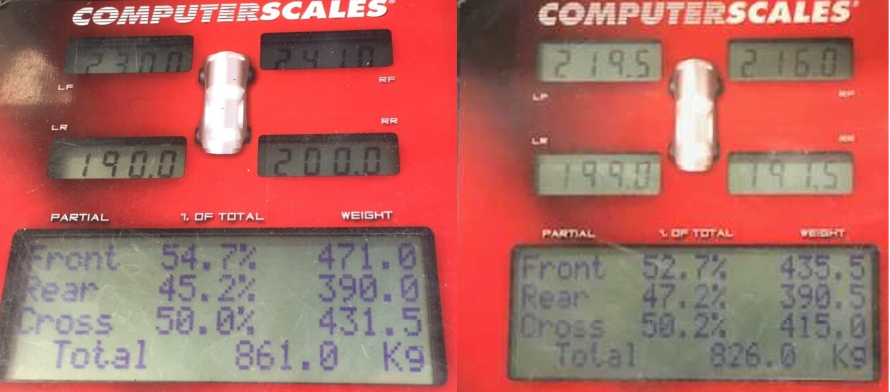
Last bits of major fabrication done (front swaybar, driveshaft hoop) and finally had it on the scales for corner weighting. Before on left, current on right: All fluids and 30+ liters of fuel on board. Little bit off my goal, but shows how hard it is to take weight out of something. Could probably get another 15kg by going to fiberglass hatch and doors, but that's just $$$ I don't need to spend at the moment. Very happy that 35kg has come straight off the front!
- 72 replies
-
- 14
-
-
-
Hyperblade's KP61R - Toyota Starlet with Honda K20a
Hyperblade replied to Hyperblade's topic in Projects and Build Ups
So managed to get it going finally after a bit of faffing around, Honda decided to helpfully change the crank sensor from EP3/DC5 K20a's to the CL7 K20a, that took a while to work out. First successful start. Starting it highlighted a weakness in the breather baffling I had done which meant oil was being pushed out. Here's Honda's original design: Here's version 1: New Version 2: Very tight fit and designed to force the air back on itself. Work has been done on the ducting into and out of the radiator and oil cooler. Radiator Exit: The oil cooler exit was a lot trickier, I needed space for the intake pipe, withour comprimising the ducting site. Pretty happy with how that's come out. Bonnet exits, still to be tided up. Big thing outstanding is the air intake, so been mocking up options. In the end I will go up with a straight simpler solution, plasitc pipe will be replaced with ali for smoothness. However I want to make sure it's got a cold air feed/box, so a bit of fabrication is going to be required around getting cold air from the head light. Here's a walk around of the whole car at the moment.- 72 replies
-
- 18
-
-
-
Congrats! I'm a little bit further down the conversion track then you which means you might find some useful information in my build thread for what your about to go through. Otherwise post up questions, and I can also try and help answer them as I've got my head around these engines now. Yours looks like a CL7 version, so a couple of things to note. They come with balance shafts which you will have to replace if you are moving the pickup to the rear, the only place I've seen offer that rear sump was Kmiata (Kpower now). https://kpower.industries/collections/kmiata-swap-parts/products/k-series-miata-oiling-solution That also needs a replacement oil pump, so it probably worth doing the timing chain/tensioner at the same time as you have to remove it to do the oil pump chain. I didn't but then realised my chain had stretched (motor had done 106,000k) by a couple of mm so ended up replacing it in the end, but i'm going for every bit of performance. I've been buying all my genuine replacement parts from Amayama as they come in a lot cheaper then anywhere else you can source them from, you just have to work out the part numbers etc. The other thing to note is the CL7 version is more like the USA K24 then a EP3/DC5 in some of it's items like water outlets etc. And the FD2 engine was based on the CL7 as well. In terms of water outlets etc I would say give aliexpress a go first, I brought genuine Ktuned stuff, and the quality was pretty poor, which means you could potentially save a few $$ by just going for the Chinese knock offs. Good luck!
-
Hyperblade's KP61R - Toyota Starlet with Honda K20a
Hyperblade replied to Hyperblade's topic in Projects and Build Ups
So I've been slowly chipping away at everything, with life getting in the way at times. Finally managed to get the extra baffle i needed for the sump, it's a Clockwise Motion FD2 baffle, meant to be one of the best and should be handle the gforces on the slicks i run. Of course even though the FD2 engine was initially based on the CL7 one, Honda decided to change the sump ever so slightly between versions, so had to modify the baffle to fit. Engine back out to fit it, clutch and flywheel all installed and rear main seal done while it was out as it saves possibly doing it later. Gearbox has new bearings throughout as the original ones at 140,000 k's had had a hard life. Engine and gearbox back together and all back in and shifter finally fitted. New fuel rail arrived, and could finally fit the FIC 775cc injectors (smallest with datasheet i could get for the cheapest price) and FPR to the mainfold and fitit all for the final time. Next was cooling, so I got some ali pipes bent up to a template I made, keeps it really nice and simple (and light) and the only joins are at the engine, radiator and water pump. The standard breather is on what is now the back of the engine, which is pointing at the firewall and would just be pain to route to. Also when racing best to have a good breather system so 2 10AN female fittings were added to a valve cover i stripped and then painted. Next up was the cabin wiring, a pretty significant job, and the final piece of the puzzle was the console. Actually quite challenging to make as it needs to be within reach when i'm strapped in and also handle the main cutoff switch which takes up a lot of room. And to get it looking half decent takes some planning. So first step mocking up position of switches to make sure I can reach them. I want to be able to easily maintain and diagnoses any issues with the wiring, so I then made a grame for everything to attach to. Worked out where to put the cutoff switch. Then wired it all up. I'm running some nice Deutch connectors at the rear so I can easily unplug them and check what the pins are doing with a multimeter. Final version all painted up But finally all fitted up Heres the engine bay at the moment Exhaust has been fitted for final time and I'm getting down to sorting out the last of the stuff in the engine bay (ducting, intake piping, catchcan etc)- 72 replies
-
- 41
-
-
-
I'm using the Deutsch HD30 bulkhead connectors and found them great. You can get a cheaper version HD20 which is composite instead of aluminum and they come in various mixtures of pin sizes max being 47. https://www.msel.co.nz/epages/motorsportelectronics.sf/sec69a2cb9283/?ObjectPath=/Shops/motorsportelectronics/Products/CONHDP242447SK https://www.msel.co.nz/epages/motorsportelectronics.sf/sec69a2cb9283/?ObjectPath=/Shops/motorsportelectronics/Products/CONHDP262447PK Total from msel would be $160incl But you will need the crimpers for the pins (but might be able to borrow some from someone) and personally I would recommend a mounting plate to stop them spinning. If you want to see an HD30 fitted in person just send me a pm.
-
Truenotch's BEAMS AE86 racecar discussion
Hyperblade replied to Truenotch's topic in Project Discussion
Just saw your video Please go and check your seat mounting, your seat is moving around way to much for my liking Here's a recent example where a seat mounting broke, note that it was a low speed crash in the scheme of things and the belts could probably have been a little tighter... You can see the seat moving around prior, but a lot less then yours... https://www.facebook.com/sambushellmotorsport/posts/1987233984751634 Ended up with damaged ribs. -
I own the car now, you can see where I took over from here It's still yellow and a Toyota (just)
-
If your looking at light engines, you should run the numbers on a bike engines turboed... Pick the right cc you can even stay in under 2L class
-
Hyperblade's KP61 Racecar "KP61R" Discussion
Hyperblade replied to Hyperblade's topic in Project Discussion
Thanks! The ducting takes a while, lots of planning, but i'm getting practiced at it now. Riveting makes it easy, no special tools required. I would love a bussmann box with more relays, I always seem to run out, but i prefer having everything centralized rather then have full amps going through a switch. I suppose PDM's are taking over that space, but they are still to expensive for number of outputs. -
Hyperblade's KP61R - Toyota Starlet with Honda K20a
Hyperblade replied to Hyperblade's topic in Projects and Build Ups
Exhaust in place for a trial fit, nice and compact. Engine side of the wiring loom done, except for the aftermarket sensors. Working on radiator/oil cooler ducting. Really happy with how they are coming out. Things are tight: So the Skunk2 Ultra Street Manifold, Skunk2 Throttle Body and the Skunk2 Ultras street manifold spaces (to increase plemnum volume) don't fit together. So you end up hacking the throttle wheel to make it all fit. Speaking of Skunk2 brillance, here's how the intake manifold arrives to you straight from the casting. Bit of hand work done to remove the casting flaws they left in it, not something you expect to have to do for the price... Intake is location is challenging so the front grill is now one piece so I could get rid the some of the brackets. Fibreglass bonnet to save some weight and to do the new exit ducting out of it. Ecu mounted out of the way: Nothing worse then trying to work on wiring in a car with a cage, so made the relay/fuse box able to swing out- 72 replies
-
- 27
-
-
-
Hyperblade's KP61 Racecar "KP61R" Discussion
Hyperblade replied to Hyperblade's topic in Project Discussion
@Roman Honda Plenum Sizing FYI RBB (06-08 TSX) Part #: 17110-RBB-000 Weight: 6.2kg Throttle body opening: 60mm (with idle bypass) Runner Length: 31.0cm Runner width: 4.4cm (min) Runner width: 4.8cm (max) Individual runner volume: 492.5cc Total runner volume: 1970cc Plenum volume: 1650cc Total manifold volume: 3620cc RBC (CL7) (supposedly one of the best) Part #: 17100-RBC-J00 Weight: 4.5kg Throttle body opening: 62mm (with idle bypass) Runner Length: 18.5cm Runner width: 4.8cm (min) Runner width: 5.1cm (max) Individual runner volume: 270cc Total runner volume: 1080cc Plenum volume: 1720cc Total manifold volume: 2800cc RSP (FN2) Part #: 17100-RSP-G00 17101-RSP-G00 17102-RSP-G01 17103-RSP-G00 Weight: 5.6kg Throttle body opening: 64mm (no idle bypass) Runner Length *1: 25.5cm Runner Length *2: 19.5cm Runner width: 4.8cm (min) Runner width *1: 5.8cm (max) Runner width *2: 5.1cm (max) Individual runner volume: 295cc Individual velocity stack volume: 105cc Total runner volume *1: 1600cc Total runner volume *2: 1180cc Plenum volume *1: 2530cc Plenum volume *2: 2950cc Torque Chamber volume: 800cc Total manifold volume: 4930cc *1 with velocity stacks fitted *2 without velocity stacks fitted RRC (FD2) Part #: 17100-RRC-000 Weight: xx kg Throttle body opening: 64mm Runner Length: ~ 19.0cm Runner width: ~5.1cm (min) Runner width: ~5.3cm (max) Individual runner volume: xxxcc Total runner volume: xxxxcc Plenum volume: xxxxcc Total manifold volume: xxxxcc -
Hyperblade's KP61R - Toyota Starlet with Honda K20a
Hyperblade replied to Hyperblade's topic in Projects and Build Ups
Been a bit quiet lately on this, I've been doing a fair bit of work on planning the wiring design and then I had to order the bits. The design was fairly complicated because of all the sensors I added, and planning the bulkhead connectors. I ended up with 2 bulkhead connectors due to the size of wiring I needed to get through the firewall, with one handling most of the engine, and the other handling high power items like Fan and EWP. Bulkhead connectors mounted with a nice plate that locks them so they can't rotate. I put myself through the High Performance Academy wiring course to tidy up some of my skills and learn the right way to do things, well worth it and @ProZac was a great presenter. https://www.hpacademy.com/courses/learn-motorsport-wiring/ My aim was to have a lightweight robust harness but that didn't use all the super expensive autosport connectors. And also no concentric twisting as that just adds more weight with filler wires. So Tefzel wiring and SE28(DR25 Copy) Heatshrink all round. I'm really happy with how the first harness turned out. The 2nd one is a bit more complicated (only half the wires)... Unfortunately I found out the Deutsch pin removal tools I got with my crimping kit shouldn't be used with the HD30 connectors as it fucks the locking tabs (bends them down to far). The tools I used were these metal ones. Where as the official ones are plastic. Of course I only found out after putting in the last pins which didn't want to stay put. I had an attempt at pulling the HD30 connector apart, and can confidently now say that you shouldn't attempt it as it's not designed to to be disassembled, I ended up braking the outer housing removing the inner pieces. But it did give me a good look at how they are designed, you would have to be very skilled to be able to fix the locking tabs in place, would need a magnifying glass and long very thin pick.
- 72 replies
-
- 12
-
-
Just for everyone else following along. Here's Jamie's engine on dyno.
-
Hyperblade's KP61R - Toyota Starlet with Honda K20a
Hyperblade replied to Hyperblade's topic in Projects and Build Ups
Picture heavy post follows: On to the finishing off the brake lines. Redone the pedal box piping so I can add some brake pressure sensors at a later stage, a lot easier to do it now then once it's installed. However it's a hell of a job fitting everything in, without the access port from the engine bay it would be impossible to get it as clean as I did. All lines are being run in the cabin to keep a nice clean look. Lines in wheel wells given some protection. Move the reservoirs which were remote to being directly on the master cylinders, saved 500g worth of hoses/fittings by doing so. Finally have a reason to add some honda performance parts... Fuel lines finished up, just waiting on a length of hardline for inside the cabin. Waiting on fittings to arrive before I can secure the pipes. TracTuff Timing Chain Baffle plate added to stop oil going up into the timing chain. Still waiting on my other baffle to be available. Engine back in the hole (will come out again) so I can work out positioning of clutch bulkhead fitting and wiring fittings. Added some Radlok fittings for the alternator and starter wires, really cool connectors, can rotate 360 degrees while attached. Mounted the EWP to the engine, very tight all around.- 72 replies
-
- 13
-
-
-
Set of TRD headers on TM for the low price of $1000... Claims 7.4kW(10ps) improvement... https://www.trademe.co.nz/2814713140
-
Hyperblade's KP61R - Toyota Starlet with Honda K20a
Hyperblade replied to Hyperblade's topic in Projects and Build Ups
So rust all repaired and on to fitting everything back together, a much more fun job. Rear diff painted, and new brake lines run. With the diff moved back, brake line won't reach chassis, so moved it to exit internally (all lines will be running inside the car) New feed and return lines run through to cabin from surge tank, using hardlines for as much as possible due to cost/weight savings. Tapped the head for the water fitting and blanked it off as I don't need it for my setup, saved 120g by chopping it in half...- 72 replies
-
- 18
-
-
As Spencer said their are so many different designs/lengths for the K20/24 manifolds. I agree with him that some of this is for different types (weight etc) of cars. I also think a lot of it is packaging in the engine bay. I.e the Euro has a bigger bay so can fit in longer runners. But same manifold won't fit in Integra without a bit of chopping, replacement. Also Honda doesn't just stick with what they know, they do try and optimise for each engine/car combo. i.e the FD2 has a range of changes just for 5HP. The American market is interesting, a lot of people are really trying to do everything on the cheap, so naturally that means it's cheaper to get a second hand manifold off a different car. So you have these massive debates on which stock manifold is better. Same with headers, PLM is the greatest for HP (supposedly), but in reality that's only because of the price of it, when in actual fact it's pretty average all round. They are always after bolt on horsepower, with no tuning, which they get away with because of the factory wideband O2 sensor. They seem to be very reluctant to actually tune a car probably because most don't have aftermarket ECU's or can't afford them. So for Quad Throttles you have the issue they are are fucking expensive for what they are, and they also don't fit in easily with a good air filter (front wheel drive life), so it's a lot harder to justify. Toyota guys are lucky as they can use the cheap 4AGE ones ($200), but if they were paying $500-$1000 for a set then it becomes a vastly different proposition. The other side is Honda manifolds are actually really well designed, so it's not a massive gain, plus of course requires an aftermarket computer for ITBs. So all round it gets to hard/expensive for most of them. I've been trying to find information on Honda K20a Plenum sizing, and have came up with fuck all, I can space my new one out to increase it and maybe? get more HP, but I can't find any data anywhere on how big to go, and the difference it would have on the K20a which is really frustrating.
-
Hyperblade's KP61 Racecar "KP61R" Discussion
Hyperblade replied to Hyperblade's topic in Project Discussion
Anyone got any good info on plenum sizing? Currently is 1.8L but I can easily add spacers to increase, from what I've seen on the internet people say around 3-3.5L is better, cause reasons... Negative maybe affects throttle response? Not sure if on part throttle how big an issue that is??? I have the space available so easy to do now... Might also allow injectors in their... -
Hyperblade's KP61 Racecar "KP61R" Discussion
Hyperblade replied to Hyperblade's topic in Project Discussion
It's a nightmare. I tried a number of things, but what worked best was a Clean and Strip Disc on a grinder e.g. https://www.thetoolshed.co.nz/product/10311-toolshed-clean-and-strip-disc-115mm?categoryId=1918 It doesn't heat it up so it comes off fairly well, it does however create massive mess (I'll still be finding bits in the garage for years to come) However you do end up going through a lot of them as they wear out, and you have to be so careful you don't catch them on anything otherwise large chunks come off. The other thing I tried that worked was an Oscillating Tools, it came off in nice flakes, the only downside was it was really hard to get into hollows and corners, but would work ok on flat panels. It was also fairly hard on the tool. e.g. https://www.thetoolshed.co.nz/product/6288-milwaukee-m12-cordless-multi-tool-12v-bare-tool- I tried a wire cup on grinder and it just smeared it. I've also heard water blasting it might be an option, keeps it cool. We had just replace the rear universal, so it was ether an installation error, or it just was a cheap universal that failed. Certainly reinforces that having a drive shaft hoop is a must. RE BEAMS, You might want to keep reading the build thread -
Hyperblade's KP61R - Toyota Starlet with Honda K20a
Hyperblade replied to Hyperblade's topic in Projects and Build Ups
Interior/Engine bay finished off: New Driveshaft done. so tiny!: I was lucky enough to be able to borrow a spit which made doing the underside possible. But what a mess it ended up making stripping the paint/underseal. Before: After: Really happy so far, looks a lot tidier.- 72 replies
-
- 22
-
-
-
Thanks for that, great video, clearly a no brainier if you can do it. So, was thinking about running staged, with some 700cc injectors I have here outboard... Still need to see if I can fit them in the manifold. But probably best not to derail this thread anymore
-
I would love to see the difference in performance of moving injectors outboard of trumpets, but a bit of work to setup for someone.