
Hyperblade
-
Posts
439 -
Joined
-
Last visited
Everything posted by Hyperblade
-
Truenotch's BEAMS AE86 racecar discussion
Hyperblade replied to Truenotch's topic in Project Discussion
Damn a lot of effort has gone into that! Does it allow you to run a bigger axle? What was the reason for doing the change? Do you have custom hubs to fit as well? -
Truenotch's BEAMS AE86 racecar discussion
Hyperblade replied to Truenotch's topic in Project Discussion
Here's roughly what a standard one looks like (your's has had a fair bit of modification done to it).
-
I just looked at B series gearsets and not actually that expensive (if you do labour yourself), especially compared to the BS K series prices. Just for the driving enjoyment I would consider it (as long as trailering the car to the racing location) I think making the car fun to drive should always be up there on the todo list as it's the whole reason we have this hobby may as well enjoy it (without going overboard). Steel exhaust makes a difference to the note, B > K in terms of sound everyday. But then again I liked Roman's video of his V6 where he said it sounded like an RB... 🤣
-
The Quaife K series sequentials are ones in particular to avoid at all costs. My understanding is they weren't actually designed by quaife (but by Momentum Motorsports) so had some fairly serious design flaws. A few people here have had to rebuild them at very large costs. Even just the ongoing maintenance on sequentials is interesting. HGT are great in that they give you the life on the components up front. https://www.hgtengineering.com/transmissions/ice-rear-wheel-drive/3mo-rwd-600-6-speed-ultralight-600-nm-450-ft-lb/ So it's not like drop it in and that's all the costs done. The more racing you do definitely the better driver you will be, also on the day you will get comfortable and up to speed faster which can mean you can focus on other improvements through out the day. However, having driven dads EK with a close ratio box I can say man it was fun even with 1600 it really made made it feel much more like a real racecar as you went through the gears (especially with the b series engine noise).
-
That's just the start, you want the decent CL7R gearbox so add $2000 and your hoping it's actually in decent condition (most have issues) as they are all high k's these days. And that's with stock LSD which isn't good enough for serious race cars, so add another $2000 for a plate LSD. Already up to $4500 (That's just part costs not labour...) Then you putting in a chassis that didn't originally have it so start adding $$$ from there, it is easy because of all the parts available, but it's not cheap. Here in CHCH 2.4L na puts you into the 2L to 3.5L class (which includes 2L turbos and Rotarys including 4wd) so how competitive are you really? On the flip side you will have a very reliable consistent race car with easy access to parts, and a cheap engine swap if you break it. Sometimes makes sense, other times not really.
-
In circuit racing, you do some of the above, and then you are now no longer racing with the cars that you used to be around, so just end up lapping the circuit on your own, which isn't that exciting. And there will always be a car faster then you even when you've spent all that money... The best moment I've had on track was driving side by side with someone (I trusted to race) pretty much the entire circuit (can't even remember if i beat him...). One thing that could actually be an investment is driver coaching, the right person can make a very big difference on how you drive the car and therefore speed. So easy to say all that, however I personally can't stop myself from improving the car, and all the shiny go fast bits are so tempting...
-
DIY casting (rubber, silicone, cement, polyurethane etc casting)
Hyperblade replied to Roman's topic in Tech Talk
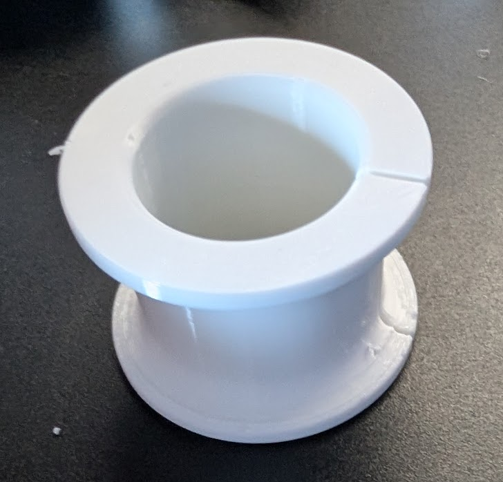
Just to give you another option. You might be able to just 3d print it direct in TPU. Tricky thing is probably getting the stiffness dialed in, which could be done via amount of infill or TPU type (probably better in this case for strength). Here's a steering rack bush i did in TPU 95a.
-
I use this Franklin Engineering kit and can confirm had absolutely no issues with it doing circuit racing. https://franklinperformance.nz/collections/oil-coolers-kits/products/oil-filter-relocation-block-fitting https://franklinperformance.nz/collections/oil-coolers-kits/products/remote-oil-filter-mount Granted when I brought it I'm pretty sure it wasn't $460, but it's definitely a quality item. For the centre adapter I got mine from Amayama, but that was Honda parts bin stuff.
-
Truenotch's BEAMS AE86 racecar discussion
Hyperblade replied to Truenotch's topic in Project Discussion
As with all aero what you should do is a trickly balance with being practical! Temps were always my concern, takes some thinking to trying and keep some airflow through the bay. At least steal the diffuser... -
Truenotch's BEAMS AE86 racecar discussion
Hyperblade replied to Truenotch's topic in Project Discussion
I'm not a fan of aluminum splitters, they get bent easily (which makes them look a but rough very quickly, although all the ones i've seen were unpainted) and don't have a nice leading edge. My recommendation (from someone not currently running his splitter 🤣 ) is plywood, you can get 2 of them out of one sheet of plywood. They are easy to shape and mount and strong, and easily replaceable. Use plywood as R&D first (with testing on track), then once your happy make the carbon version. Either way having some pucks will definitely help anything you make last a lot longer. One thing to note from an aero point of view, i was recommended to have my splitter go back to the firewall (and seal to it), and also seal off the wheel wells. -
Hyperblade's KP61 Racecar "KP61R" Discussion
Hyperblade replied to Hyperblade's topic in Project Discussion
Thanks, I record all of them just for fun. No I didn't, it does actually have that mode available but it then does purge tower which seems like a waste of filament just for a photo. I just got lucky with timing between shots! -
Hyperblade's KP61R - Toyota Starlet with Honda K20a
Hyperblade replied to Hyperblade's topic in Projects and Build Ups
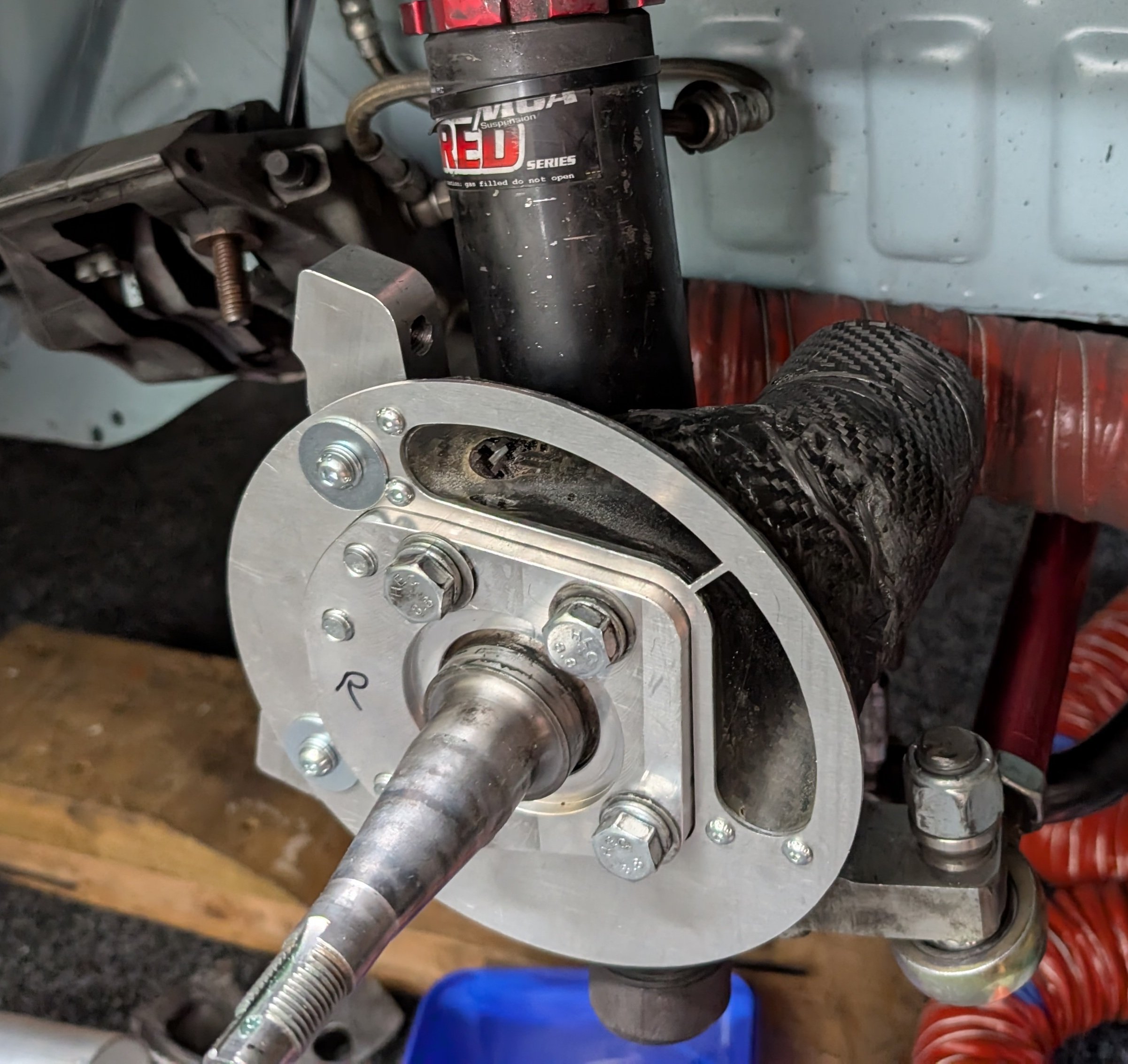
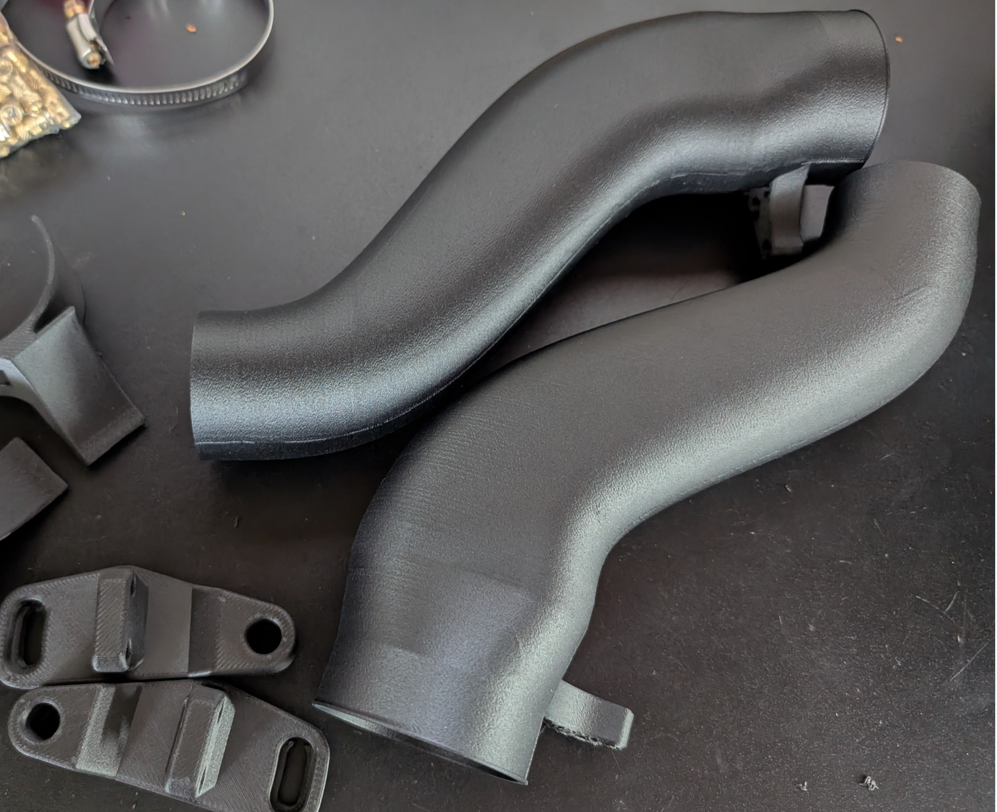
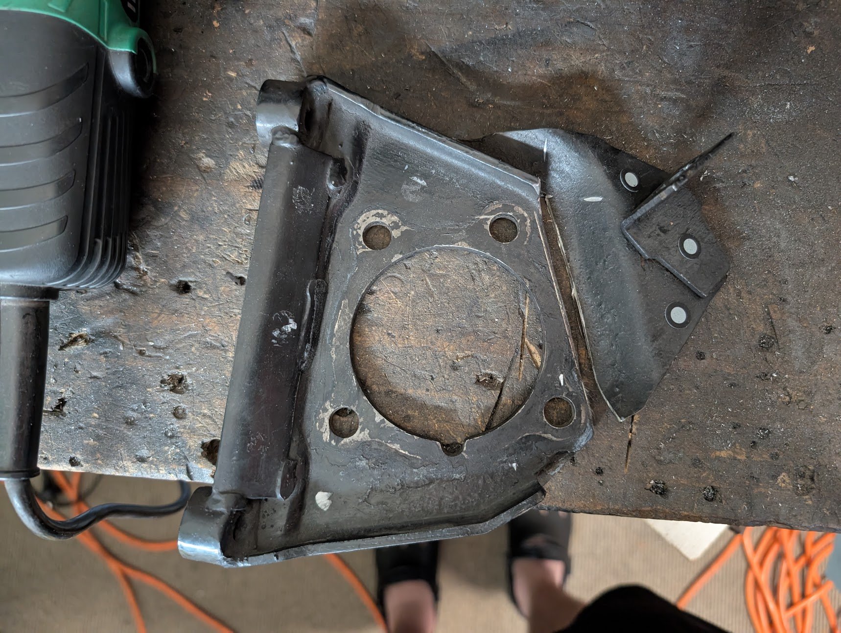
Final versions of the front brake ducting have been printed in PA-CF (Nylon/Carbon Fiber) and fitted, came out great (It's super strong), The ducts have brass heat inserts for threading the bolts into which have turned out far stronger then I expected which is awesome. I have some new silicone hose coming as the aliexpress stuff i have is clearly below par and that's the front done all done. Weight each side is 150g (including mount). Them printing: Onto the rear now, I've chopped up the already modified caliper bracket to get air into the center of the disk, will do the other side, then fit them and 3d scan and make something to guide air into them.
- 78 replies
-
- 17
-

-

-
Truenotch's BEAMS AE86 racecar discussion
Hyperblade replied to Truenotch's topic in Project Discussion
I'm getting old, forgot I had already showed you that too. Your best positioned to know if it's safe or not, your video may be making it look worse then it is -
Truenotch's BEAMS AE86 racecar discussion
Hyperblade replied to Truenotch's topic in Project Discussion
Sorry didn't realize I had already nagged you about it. The reason why I'm concerned is that even in a slow speed impact it creates loose belts and injuries associated would be worse. We had a guy up here in roll over with similar seat movement and it wasn't good. Good to see you out racing though! Looked like fun -
Truenotch's BEAMS AE86 racecar discussion
Hyperblade replied to Truenotch's topic in Project Discussion
Watching your latest race video... The movement in your seat concerns me from a safety standpoint... Plus can't be helping with the feel of car. Do you have version with back mount? Can definitely recommend doing that if you can. -
That's good to know, this particular project I needed Simhub to support it so they had a list of versions they required which the nano wasn't on it. I'm good on shield, went with a Adafruit clone so that should work with the motors for the amps required, haven't run it yet as I need to re print housing for USB A port.
-
Genuine one just arrive ($30 delivered from within nz), 30s later software is all successfully loaded via SimHub (I had Arduino IDE and drivers already installed). If your thinking about playing around with Arudinos, spend the extra $10 and get the genuine one and save wasting time on dealing with the drivers. @h4nd Was serious about giving you the clone, I'm sure you can find a use for it if it is working correctly. Next time I see you will give it to you (unless you want it earlier for something just let me know.)
-
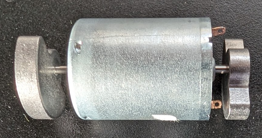
Hah, yes but virtual. I'm sim racing online at the moment, and you can buy rumble kits for the pedals (e.g. so the pedals vibrate when ABS kicks in) https://www.sim-3d.co.uk/product/pedal-rumble-motor-kit/6?cp=true&sa=false&sbp=false&q=false&category_id=11 I thought surely I can do it cheaper. No coding required as the software SimHub (https://www.simhubdash.com/) manages the install to the Arduino then the communication to it. So was originally just a simple 3D Print some brackets for the motors 3D Print the box to hold it the Arduino and Motor shield. Wire it all. Plug it in and watch it work. Turns out trying to do everything on the cheap wasn't the best plan. That and wiring the motors does my head in, why would you give the contacts the smallest gap to the spinning weight???
-
Thanks, but I've lost my patience with it. I'll just buy a genuine one, the amount of time I've spent on it now has far exceeded the price difference and the aggravation is so not worth it. You can have this one, odds are it will work perfectly for you especially if you have drivers already installed.
-
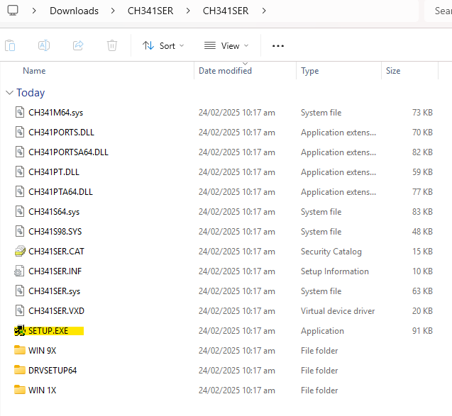
This one (actually trys to install 3.9) https://www.wch-ic.com/downloads/CH341SER_ZIP.html But have also tried this one with no luck. https://sparks.gogo.co.nz/ch340.html
-
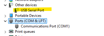
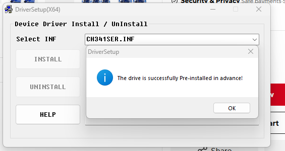
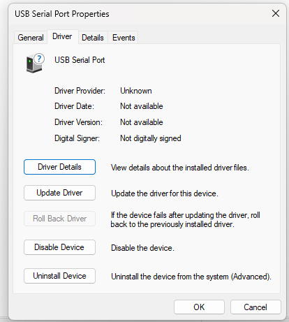
So first time trying to play with an Arduino for a project and now wishing i spent the $15 extra and got the genuine one... Anyone got some advice for drivers on windows. It's a clone Arduino Uno R3 off Ali Express with CH340G usb chipset (ATMEGA328P-AU) and USB C (https://vi.aliexpress.com/item/1005007335850929.html). The board powers up and has flashing light. But I just can't connect to it using the software, all signs point to it being the USB drivers. I've tried different things (uninstalling drivers via pnputils) and currently this is what it looks like. I got to this stage after uninstalling via pnputils the FTDI driver as i noticed that was being used in the properties, previously where it was showing up under Ports (COM & LPT) but had a generic name and COM 3 but just wouldn't connect. I've run the CH341 driver install (as admin)(3.9.2024.09) But always get this message. Uninstalling doesn't do anything as says device is not installed. Tried updating drivers, but doesn't do anything. Any advice on what to attempt next?
-
Hyperblade's KP61R - Toyota Starlet with Honda K20a
Hyperblade replied to Hyperblade's topic in Projects and Build Ups
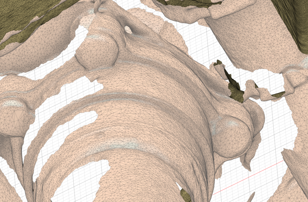
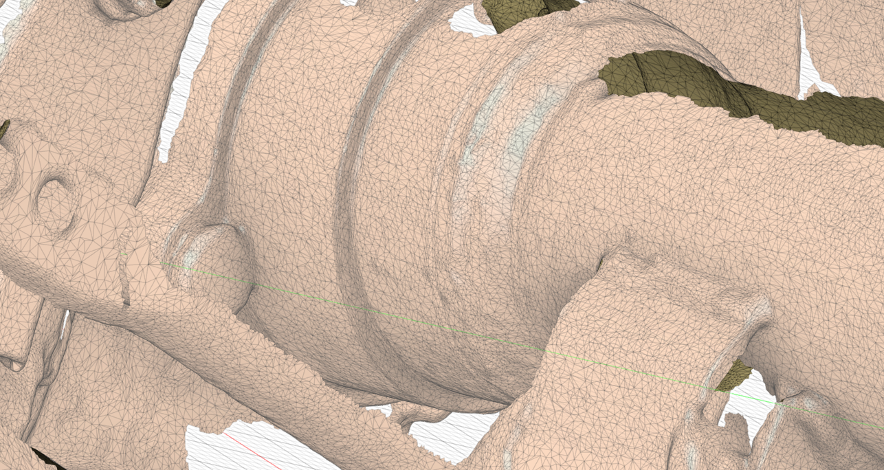
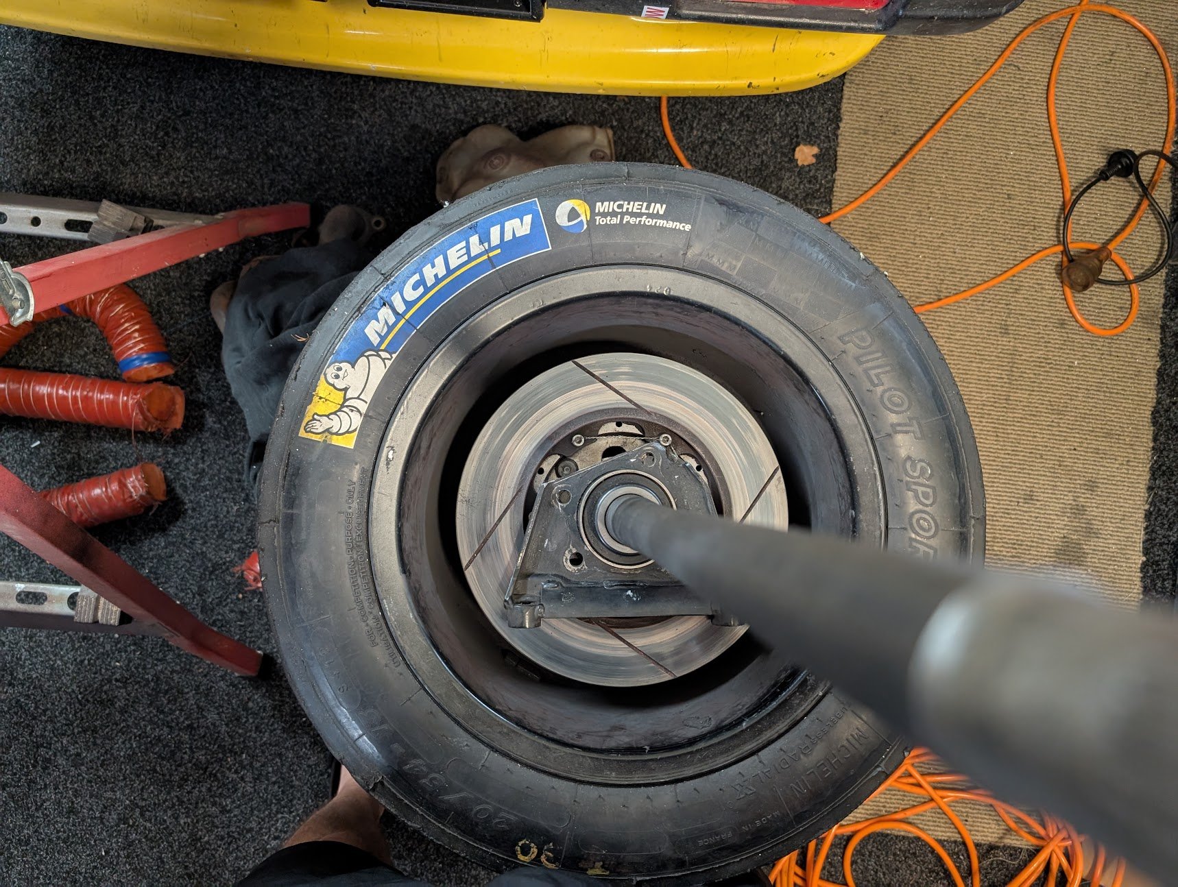
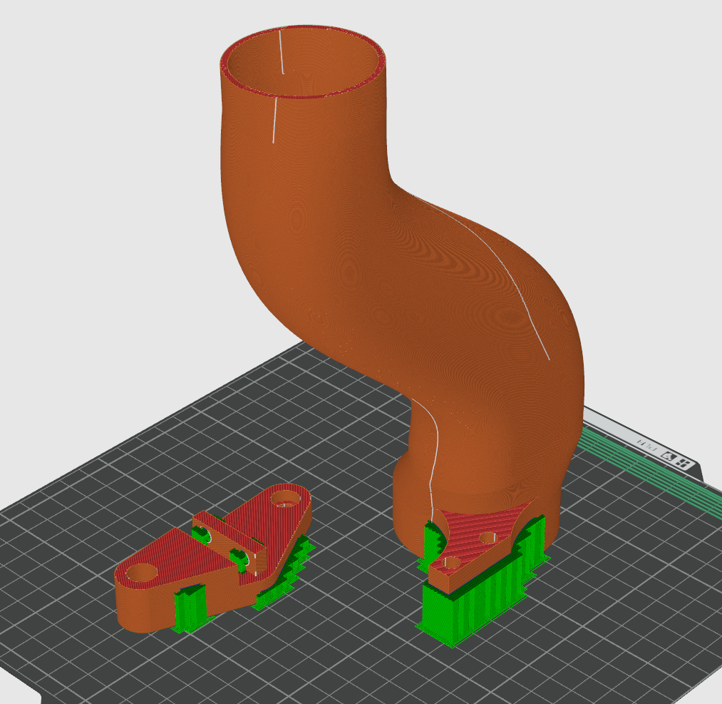
Next step is to get the hose to them, I want to redo this area so I have a nice transition from the spoiler inlet which is 2" to the hose which is 2.5" and I want to provide some better clearance to the wheel so it doesn't rub through anything. So finally got out the 3d scanner and this is my second attempt at scanning the inner fender well (einstar via laptop with USB passthrough to desktop to test if i could do it remotely without dragging desktop with me...). Pretty happy with it, and can really see the benefit of scanning an area when trying to fit something into it. So prototypes are now being printed in PLA to see if the real world matches the virtual, weight of mount + duct is 130g (PLA) which i'm pretty happy with.
- 78 replies
-
- 11
-
-
Hyperblade's KP61R - Toyota Starlet with Honda K20a
Hyperblade replied to Hyperblade's topic in Projects and Build Ups
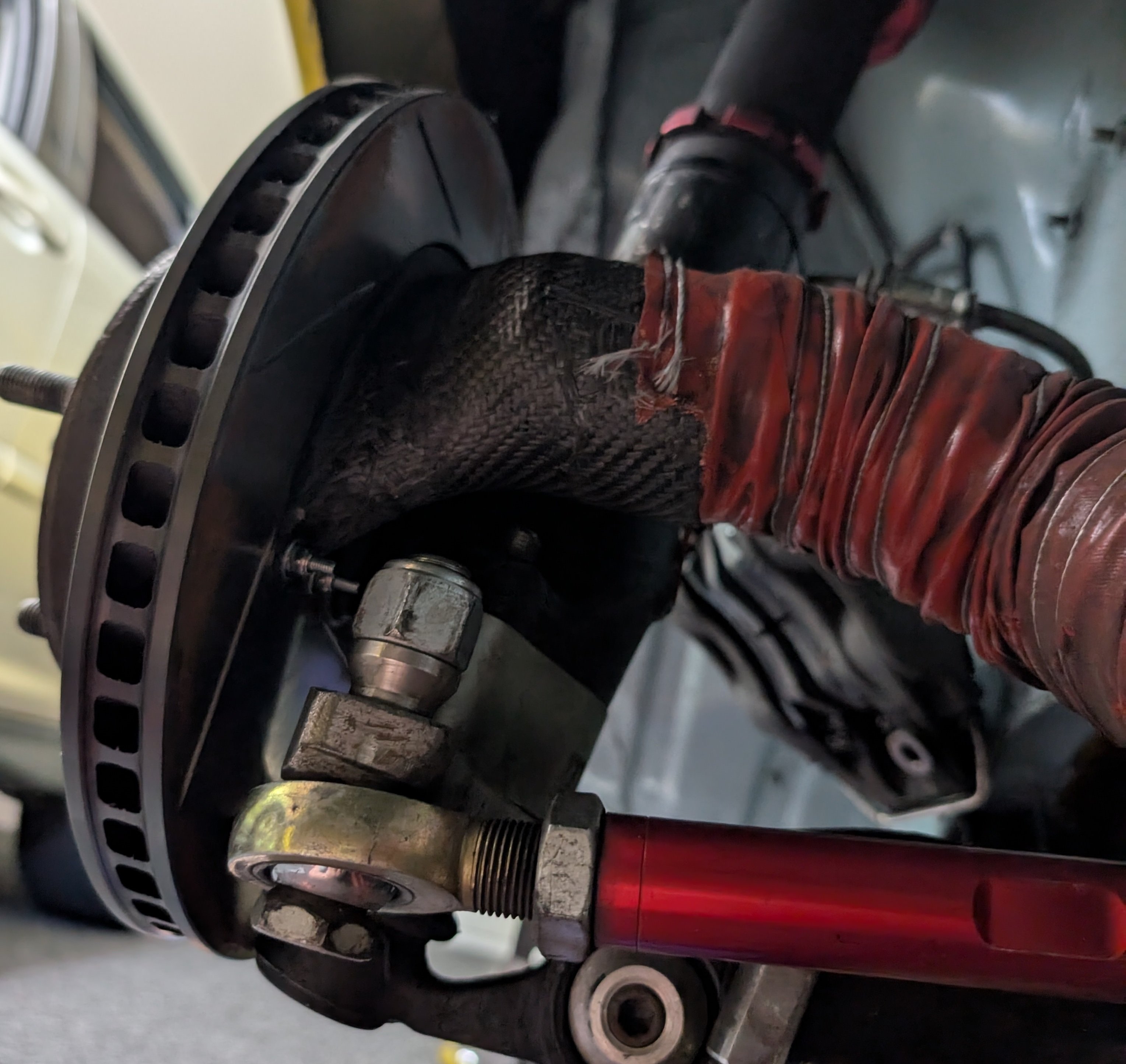
Slow progress on this, but chipping away at it when i can. Carbon fiber ducts are fitted up, I just need to glue them to the plate (for additional strength) which I will do as the last step.
- 78 replies
-
- 11
-
-
There is a lot of weight savings to be gained in this area, k20 water pump housing is 5kg which is insane, the engine mounts are equally heavy, definitely worth focusing on this area in the future if your trying to save weight $/time spent is well worth it for the gains.
-
That's an awesome weight! Goes to show how over weight the 3SGE Beams really is.

.png.cb87b102026d2c16af503e2ad4044bfc.png)