NickJ
-
Posts
3375 -
Joined
-
Last visited
-
Days Won
1
Everything posted by NickJ
-
Is that what looks like a hex on the top?
-
Watching with great interest, I had resigned to getting someone else to do it but this has swayed me back, fiddlesticks.
-
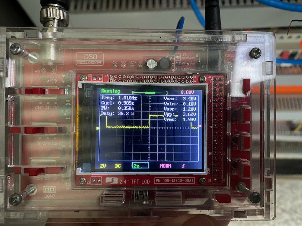
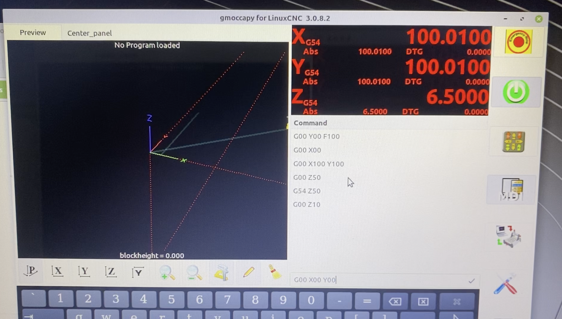
WTF was I smoking and where did I leave it? Fired up the machine today and sure enough, same issue with axis creeping on the encoders, with multimeter in hand I started checking the obvious... 5V ground to system ground....30mV - Nope, not there. Utterly disappointed at this hypothesis being wrong I clutched at easy straws, 24VDC ground to system ground........ 30mV Control board ground to system ground....... 30mV OK, lets see how you like oscilloscope! Hmm, thats a pretty good square wave coming back from the encoder, for noise..... Almost as if the axis was moving............ The good old tape around the screw trick soon showed that yes, the axis is actually creeping, not just one, but all 3, last session I was sure to confirm nothing was moving, I have no idea how I missed this, but there you go, sane conclusion to that issue and even better, I have working encoder feedback! Next question then, why does the machine error out as soon as I try start it? first guess was the lack of limit switches, getting these wired up was quick and easy but gave a new error, active axis vibration, aha! I've seen this before, what PID values are in? It would seem that default PID values are P=50 I=0 & D=0, not sure I can do the best to explain here, these fancy values are what allow it to get to where it wants to be, in short with P set too high, the system will vibrate obnoxiously, dropping this to P=0.1 will have terrible response (more on tuning to come) but with stability. So dial in the change, hit the enable switch and everything behaved! Scrubbing up on g-code from many years ago I gave the machine a quick jog around and confirmed travel scaling is within tape measure precision, later on i'll dial this in better, the current plan is to just get things going. With movement in all three directions, I moved to the VFD, again, wiring had to be converted from sinking to sourcing but soon had the output reading correctly (to my understanding) Switching on power to the VFD I hit go at 1000rpm only to be greeted by the sound of a jet engine taking off! It would appear the go command gets through but the speed reference is not quite doing anything except shooting to the moon. I'm unsure if this is wiring based or VFD based but leaves the next move as going over the VFD wiring (again) and comparing that with the manual (again) which will then be confirmed with the VFD internal settings.

- 60 replies
-
- 15
-

-

-
You bloody ripper! My eyes lit up when you posted those pics on your build thread, all we needed was someone to see if shipping would work, thanks for doing the honours!
-
Just twist the 5V wire to earth........ Haha, yeah thats terribly written, I think the 5V supply isn't grounded correctly which has left the 5V floating, well at least thats the simplest answer to what is observed.
-
Last weekend I wired up the CAT6 cable to much better results. All axes return sensible values with movement until they're stationary, then the input starts creeping, it would appear I have a pretty large noise source somewhere. In chatting with men of greater knowledge it sounds like input noise, likely my 5V supply rail not appropriately earthed. So in the usual weekend mode i'll push all the toys outside, liven up the machine and have a poke around with the multimeter/scope.
-
yes, but they've locked some features away behind paywall, i'm not up to date on the details, but thats the way regular users have informed me. Also been told of loopholes via free internet courses which may be worth exploring.
-
Oooh, like calibration cuts, circles/shapes etc? Have had a thought in my head about how to verify certain things, if that is such a thing?
-
You understand how much i'm banking on this then! So getting the axes to work is pretty good as once one runs, its pretty much copy/paste but..... The X is 3.5m long and currently half buried under usual shed stuff so its out for testing on. The Y is 1.5m but if running away would smash the side of the Datsun. Which leave the 250mm of Z as the obvious to test on, except it has a brake which if released too soon dumps down to full negative, tripping the overtravel alarms and because I never noticed, then spend an hour trying to find why the servodrive enable contactor wouldn't pull in.... So the only way to test each axis is to drag the Datsun out into the carport, clear the table (just in case) and test on the Y axis. I'm reasonably confident that once running the VFD will be straight forward then a full dive into classic ladder to enable all the required pneumatics, my hope here is that there is pretty basic feedback so at least trial and error has a better chance of success compared with the software oddities currently plaguing me. Oh, and then a G-Code refresher Followed by hasty CAM refresher And likely forking out for Fusion360 to get all the toolpaths
-
Everything is such a bloody battle until I screw up, then its obvious that at the 50/50 chance of getting it right I chose wrong.
-
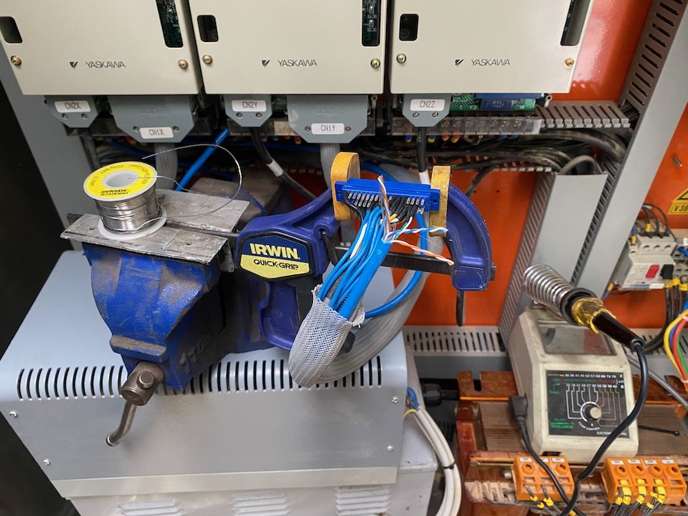
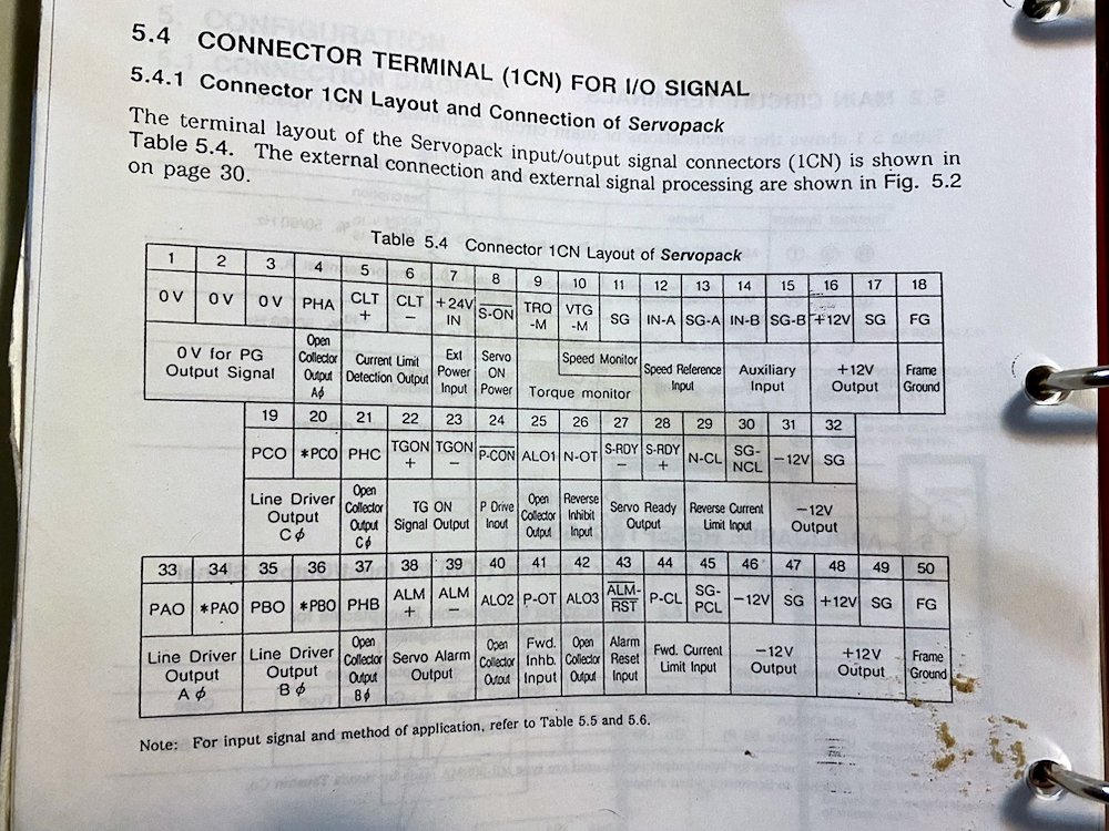
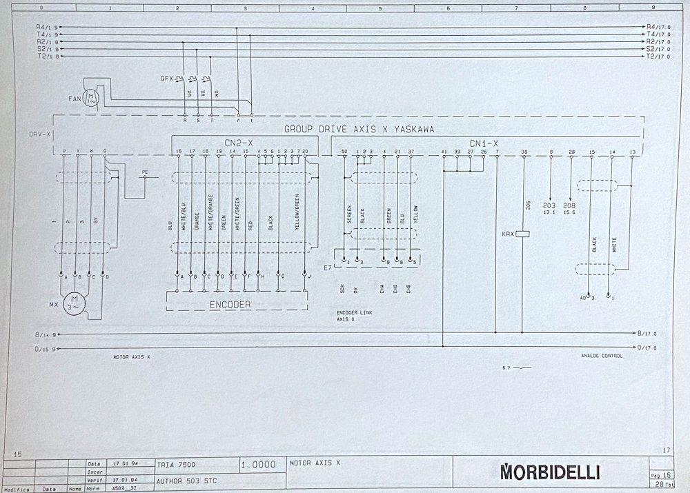
Successful weekend with getting all axes to move via Linux, unsuccessful due to hopes and dreams wiring. The old controller used a 4 wire feedback loop, what appears to be each phase of the encoder ChA,Chb,Ch0 + gnd, I took a massive assumption and just hooked each phase up to the 3 positive inputs on the Mesa card. Nope Nope and Nope, although open loop shifts things (I obviously got the AO signal and enable in the right place) into closed loop just ends up in runaway, or as i term it, a good test of the E-Stop circuit.... Thankfully in the folder of schematics there is also the servo drive tech sheets Digging through the wording, the drive bounces the raw encoder signal out pin 19,20,33,34,35 and 36, it is these that I should have used. Today I picked up 12m of CAT6 which should do the trick, now for a spare day to open up the fiddly little connectors solder and route to the Mesa.... While I had everything powered up I messed about with the air controls a bit more, using clippy leads I went through the control solenoids one by one to see what actually worked, surprisingly I managed to get the spindle to release and grab a tool holder, will need much more work to get tool changes running but its a slice of motivation I needed after the wiring woes.
-
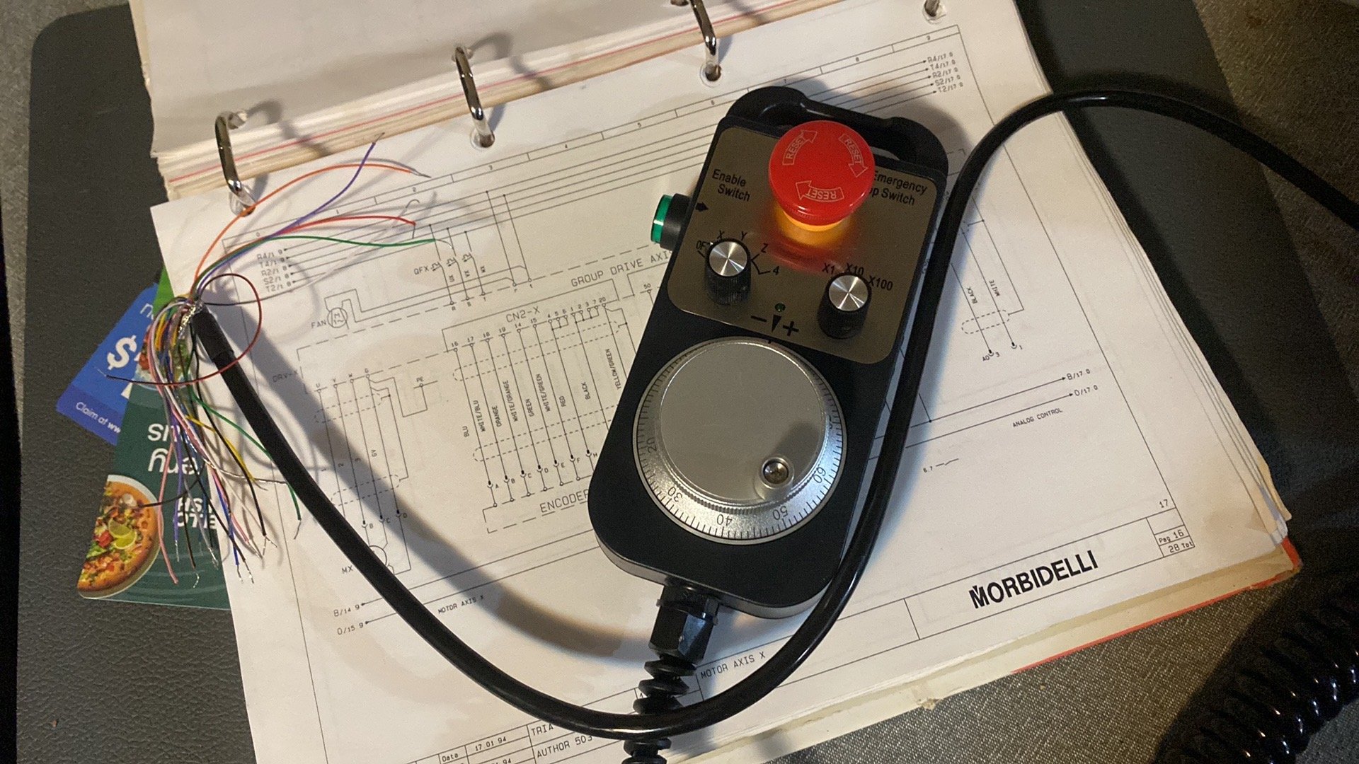
Yeah so i tried the latest LinuxCNC version but it just didn't want to fly with my computer, I had some potential causes rattled off but my inexperience could not comprehend what i was being told. In the end, the good man who is helping me gave his custom Mint setup which in comparison loaded happily, as I have no idea exactly whats going on, working = good and i'll just keep running with this option (until is doesn't). Yip, the MPG will wire to the Mesa 7i77, i'm not 100% the exact pinouts just yet, but i'll get to that in time.
-
Sounds like insulation breakdown in the armature, know anyone with a megger that could poke it for you? standard multimeter will have trouble diagnosing it.
-
Oh, there is a stack of content there, cheers! Do I spy your lathe mods inspiration?
-
Huh, good point! There is one at work, it does my head in. A summer student got it running properly so should give it another look.
-
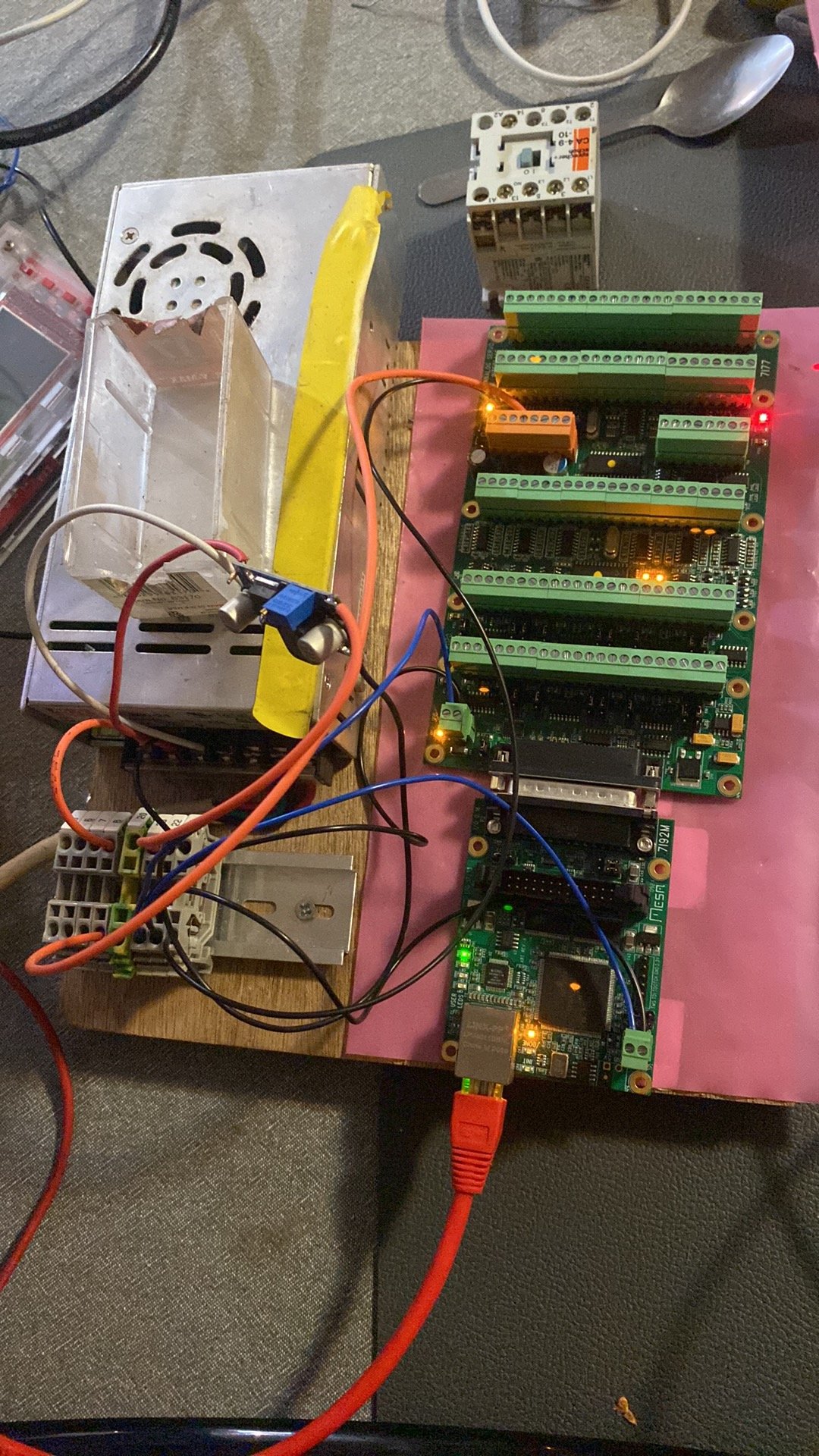
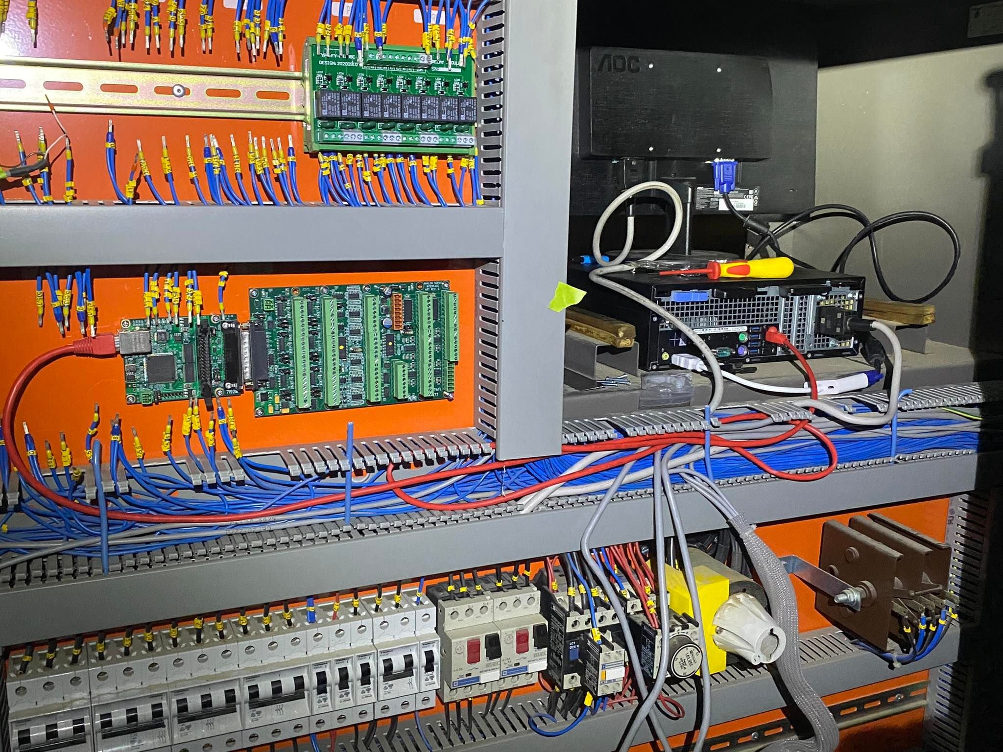
Game on, let the electrons flow* *in their designated channels Wired up the mesa boards on the table to try get my head around things, notable learnings were -I have no idea how IP addresses work -How I thought the software worked was wrong -The computer really doesn't want to talk to the boards In what was similar to loosing one's virginity, I was hastily added to a FB messenger group of CNC Barries the world over, one of which in rapid fire time soon had me up and running, I still read back through the thread and don't quite understand what happened, but hey, the computer and linuxcnc are now friends, it works! With that, one would go back to the books and confirm the learnings, but nope, no time for cautiousness, straight to the install phase Removing the factory controller and interface boards, I mounted the Mesa 7i77&7i92 boards in their forever home and started trying to identify all the connections that needed to be made. One thing that has been making me nervous is the limit switches and safety circuits are all on 110VAC, the quick fix I thought would work was to switch this over to 24VDC to work with the new controller, this lovely dream was sadly cut short by the 110VAC being used for latching contactors, to replace the E-Stop and Servo drive contactors with 24V models would be another large expense disproportionate to the purchase price of the machine. In digging through the schematics I found there was a 24V circuit to the controller, turns out this is switched by auxiliary switches on the two main contactors (mid right above) only change needed is they are going low, I need them high - swap the 0V for 24V and we should be a go! Once the E-Stop and safety circuits are communicating as expected, i'll try fire up an axis, my original plan was to mechanically isolate each axis as I test to prevent undesirable runaway, in another twist it looks like I would have to dismantle large parts to get such an effect, as its pretty much a 50/50 chance of getting the direction input correct, runaway axis drives is pretty much a given, with faith I can rig both safety and activate circuits, I'm going to try limiting the drive speeds in the software with a ready hand on the E-Stop.......
-
You got it right?
-
Mate tried earthwool on his racebike, worked for a few days then the binders let go and it all collapsed, imagine Kaowool would be much the same.
-
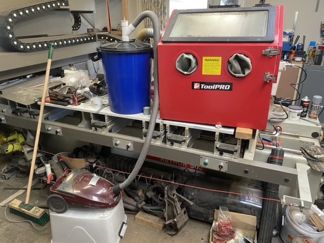
Supercheap cabinet on loan from benno, wired up some led lights he supplied for instant improvement then today fashioned a cyclone from two large buckets, pvc pipe fittings all finishing off with an old air filter from the landrover, so far, it sucks Amongst the random bits that came with the router was an assortment of air treatment gear, have a large filter/water separator on both the compressor and blasting cabinet, no sign of moisture entering the cabinet so far, happy days
-
Might as well frame the deck from uni-strut
-
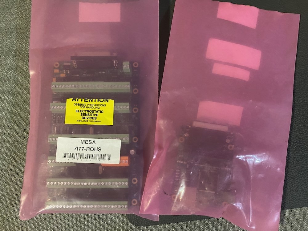
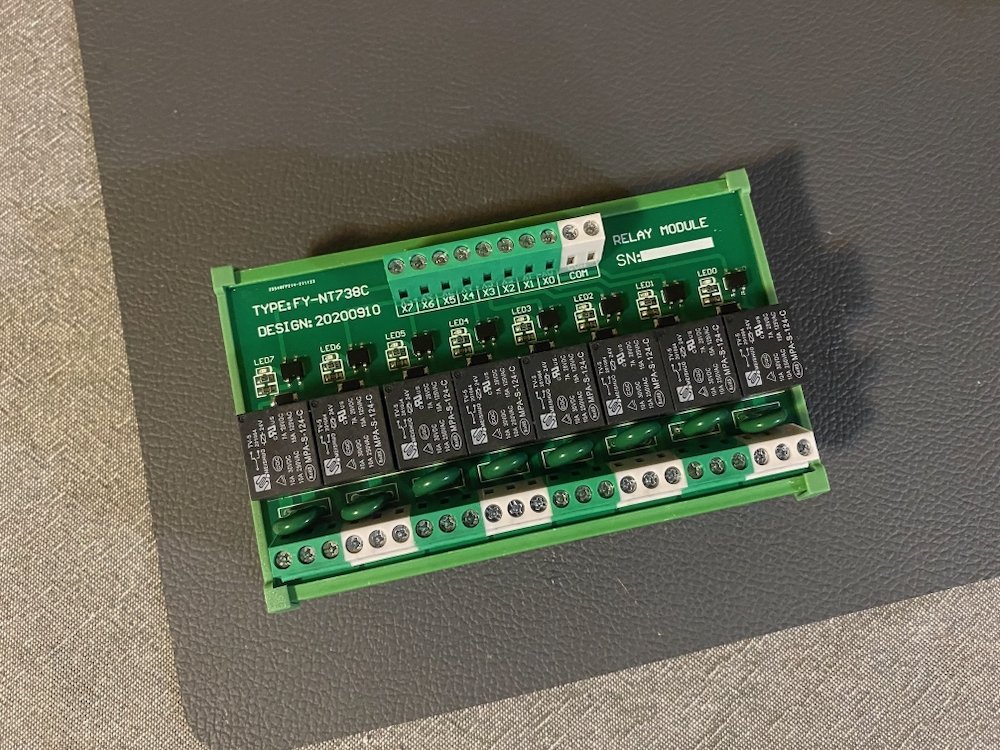
Fricken mail day! 7i77 6ch servo control board and 7i92 Ethernet board. 8ch relay output module, I expect many more of these to end up in the system, this should be enough to get started..... On lesser (But way more important issues) Loading Linux onto the computer has been a ballache of learning about stuff I care little for. It turns out Debian(OS) and linuxcnc are not friends which I lost a few evenings trying to figure out, that lead to a copy of Linux Mint being wired my way "Just hit load" Yeah right Kept getting a "Grub2" error, who? what? eh? So i've now learnt more acronyms that still mean little but the gist is; -Enable legacy boot (in BIOS) -Custom install partition table -reserved BIOS, swap and main partitions With the OS loaded to the hard drive, a healthy reward was the latency dropping from well in the no go range to well inside the preferred range, stoked. Another weird issues was the cheap VGA adapter, for some bizarre reason boot screens don't pass through meaning I had to borrow the girlfriend's office monitor to fiddle in the BIOS, this had me thinking I had bricked the computer until sanity suggested the logical problem solving technique of trying a different monitor.... Slow progress, but moving forward and closer to hardware movement!
- 60 replies
-
- 10
-
-
-
yep, quite common in production of small fiddly stainless stuff, not sure if anyone in NZ is set up for it though? We have stuff sourced out of Europe that has extensive laser welding, very pretty and low overall distortion.
-
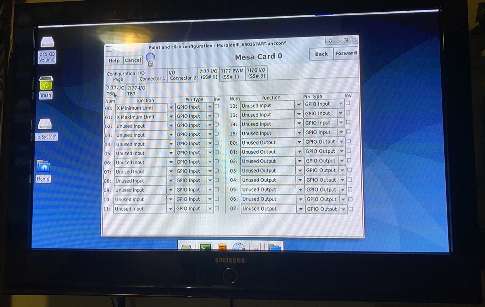
Fun hands on stuff is beginning! Cheers to @- i5oogt - for sorting me a PC, unfortunately my ancient screen didn't have hdmi/dvi so the TV took over. Standby for noob problems, this is my first ever PC, fumbling through BIOS and formatting bootable USB drives somehow happened (Credit youtube/google) and we have linuxcnc loaded up, running latency tests was square in the 'not suitable' window ~1,000,000ns but for now I will ignore it, as my confidence grows i'll work through diagnosis and checking suspects off the list. Its a massive steep learning curve, but happy to have booted linux and loaded up a mock machine, most of it makes sense and the few questions that arose were easily researched and answered if the "help" tab top left couldn't assist. A few weeks back I was informed to buy a certain MPG from our dear friend Ali, in record time it arrived, decent quality and heavy in the hand, hopefully it performs as expected. The MESA boards should be on the way, might be some long nights when they turn up! All for now, stay tuned!
- 60 replies
-
- 11
-
-
For sure its beaten up pretty bad, but is there any sign of fatigue in there evident that a fracture started at the oil holes? Hard to tell from the photos but appears to be a transition in cross section so holes just happen to be in the likely failure region?
-
Pass, most of my use is below max load and cyclic