Adoom
-
Posts
2195 -
Joined
-
Last visited
Everything posted by Adoom
-
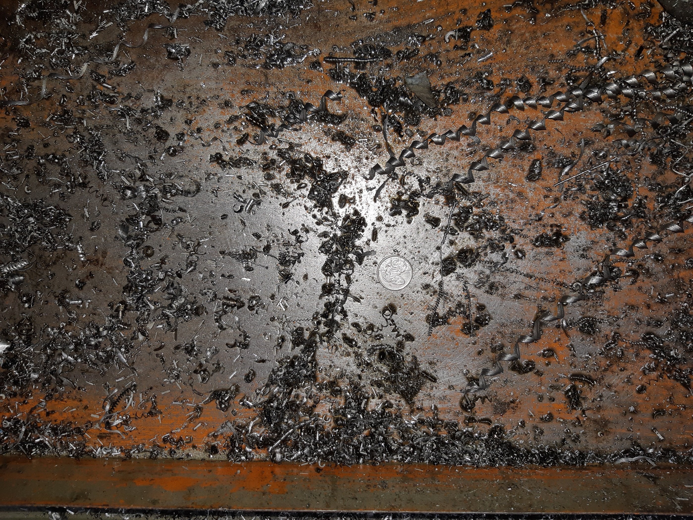
I dropped a 2.5mm screw.

-
Isn't the boot pull in the box between the seats?
-
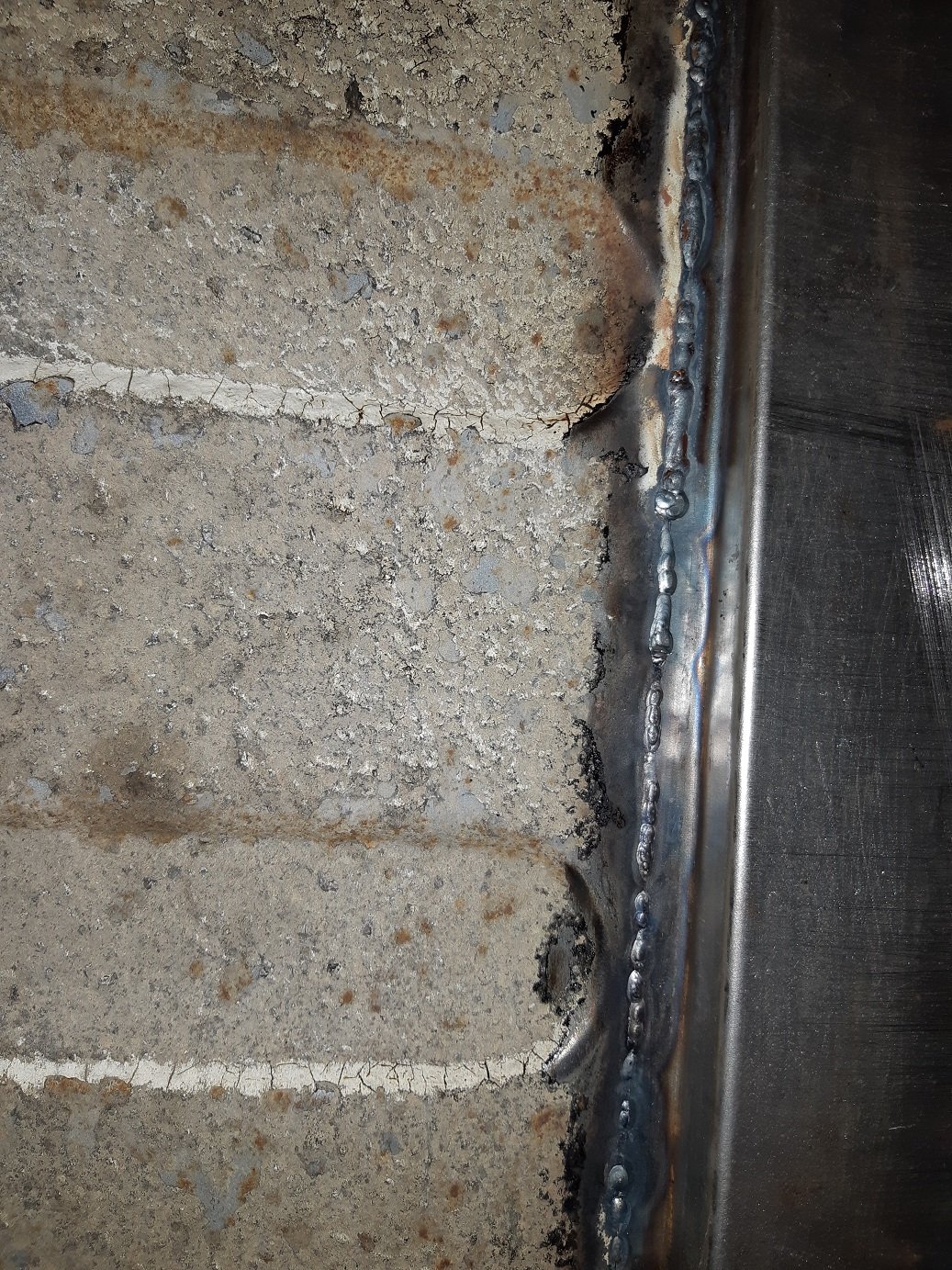
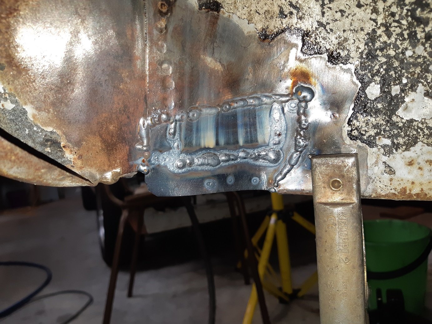
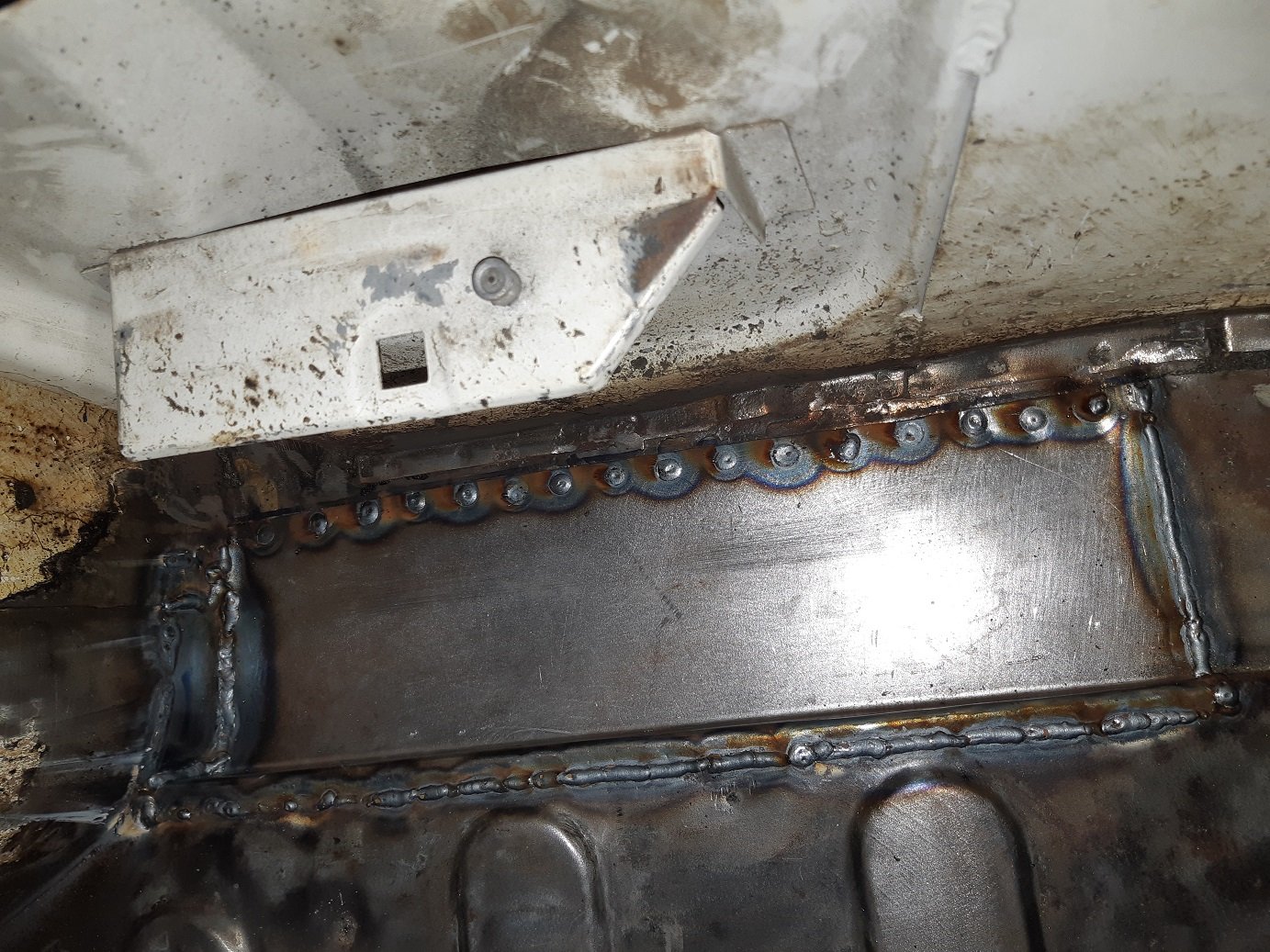
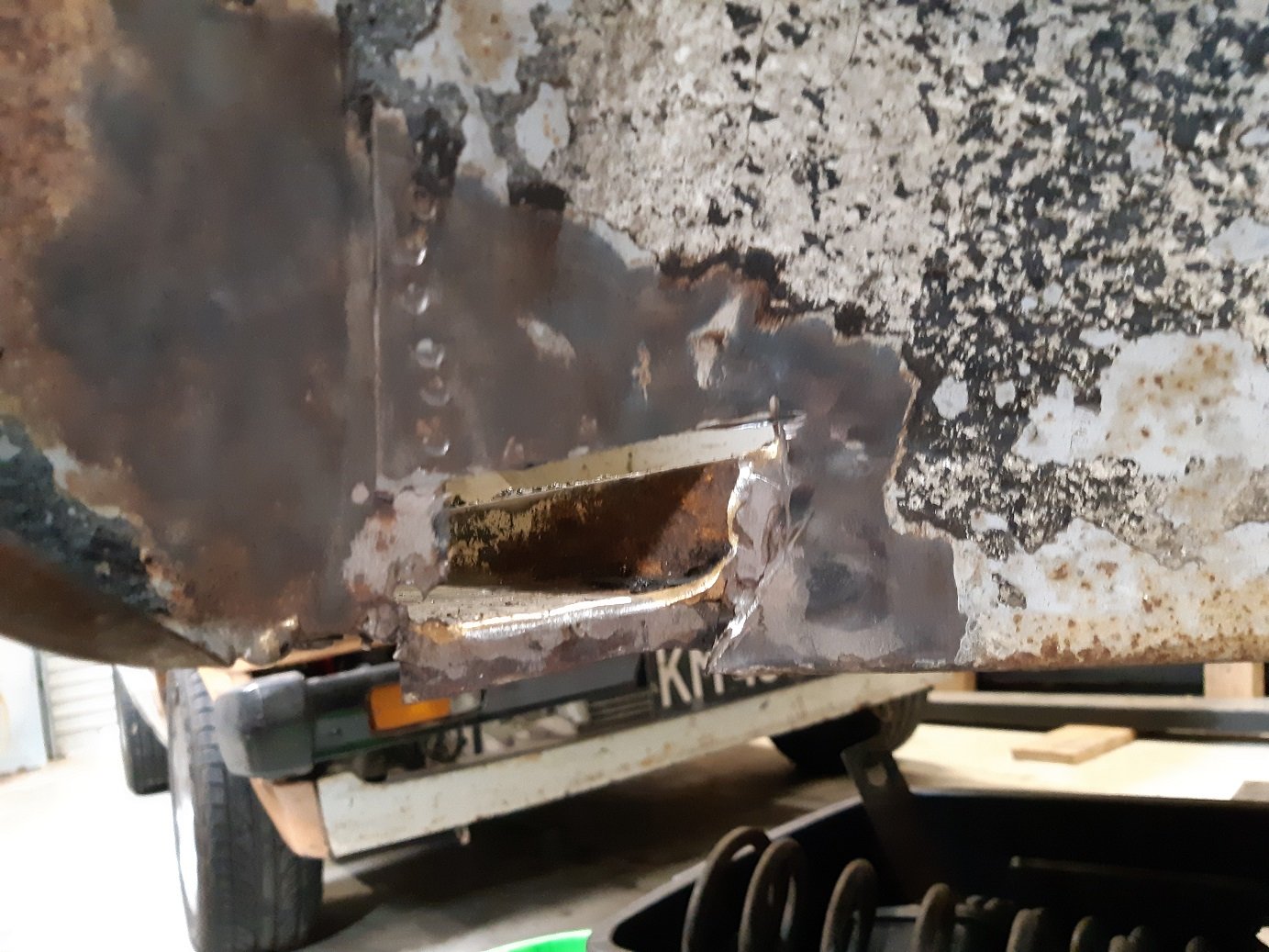
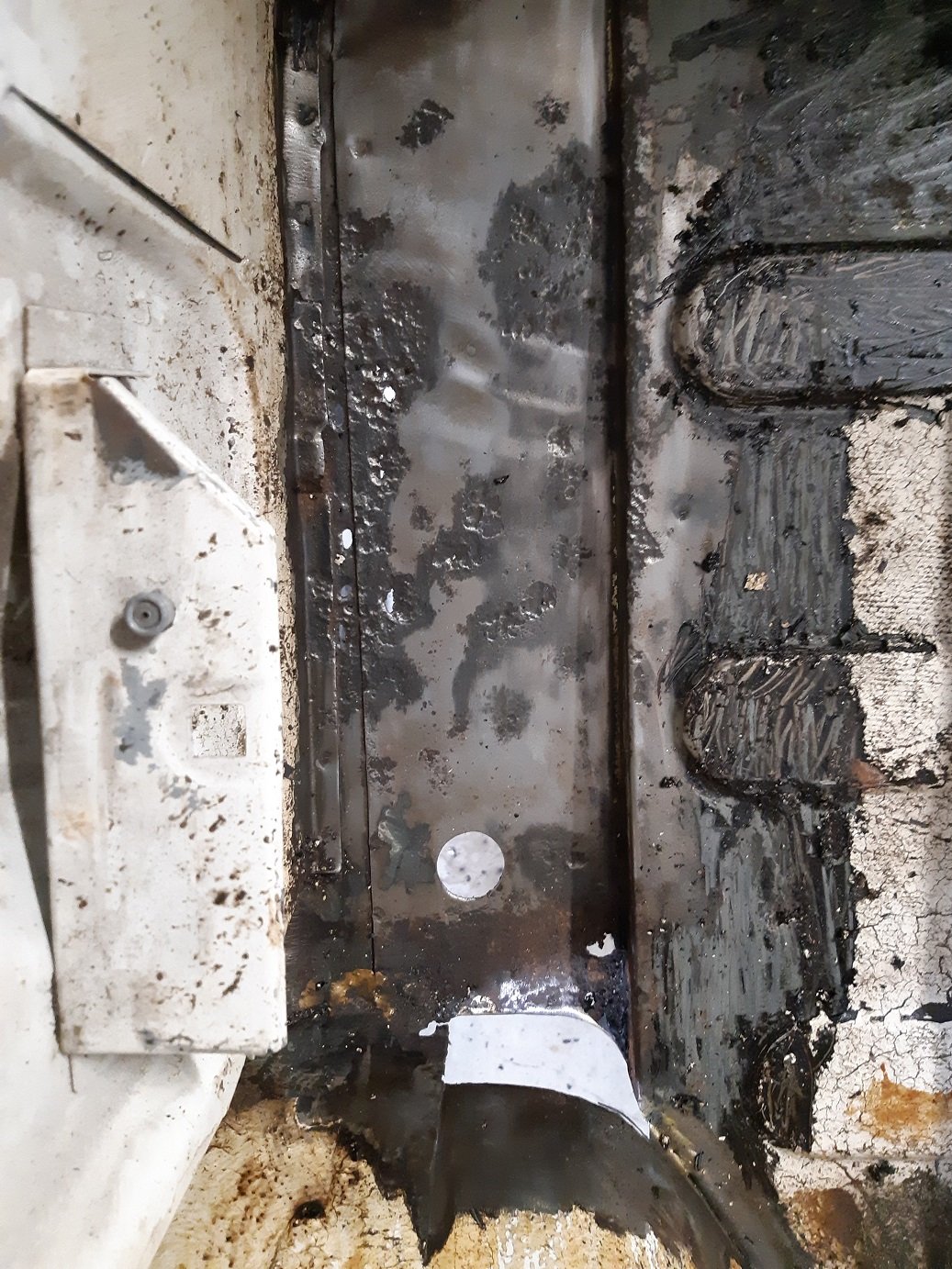
One of the two areas where there is rust. In the boot/rear quarter. Got decent penetration. I made use of a copper backing plate(a squashed copper pipe) for the long butt welds.
- 191 replies
-
- 13
-

-
What's the fitting made of? Can you get some weld onto it? That should loosen it up.
-
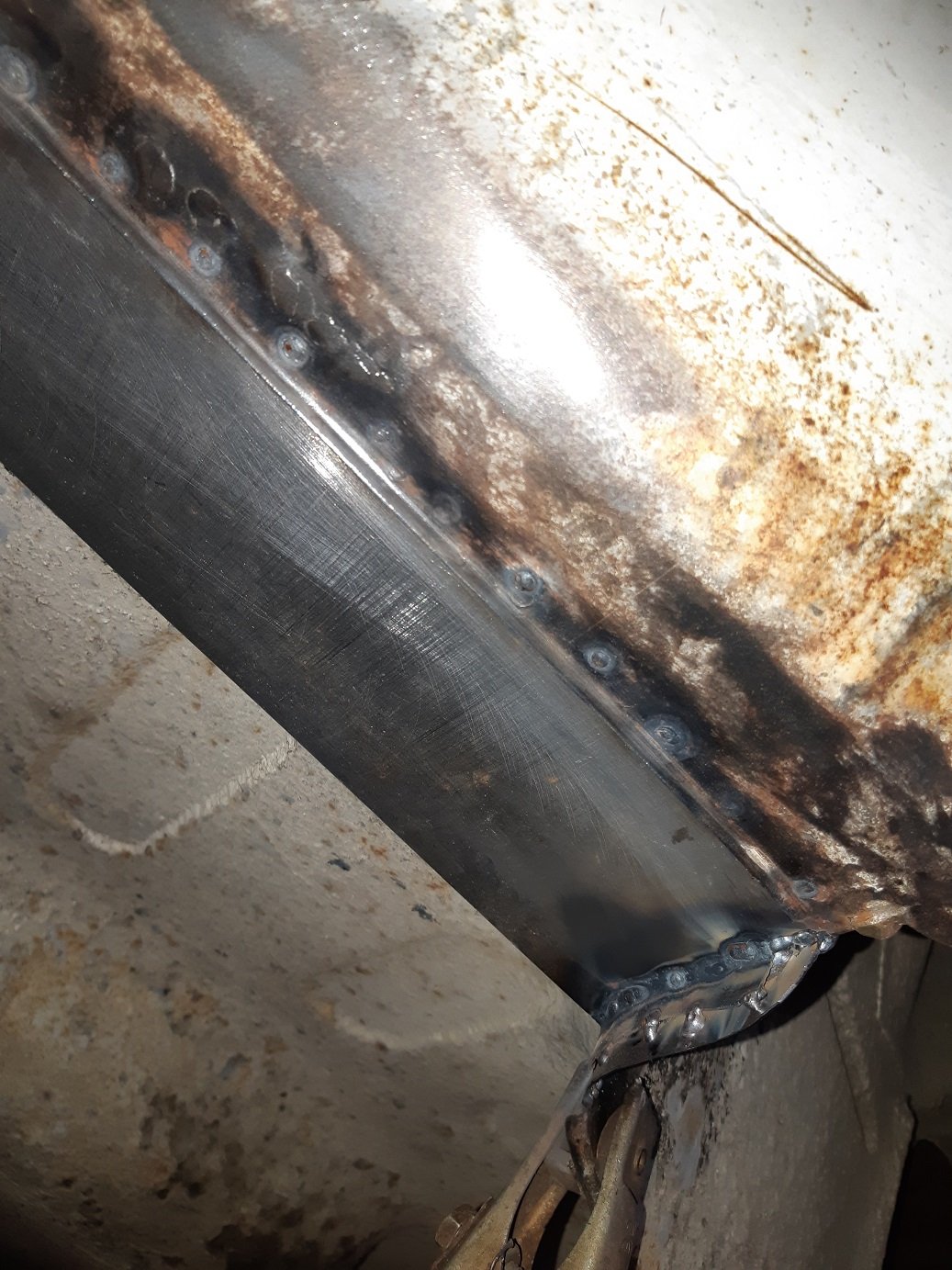
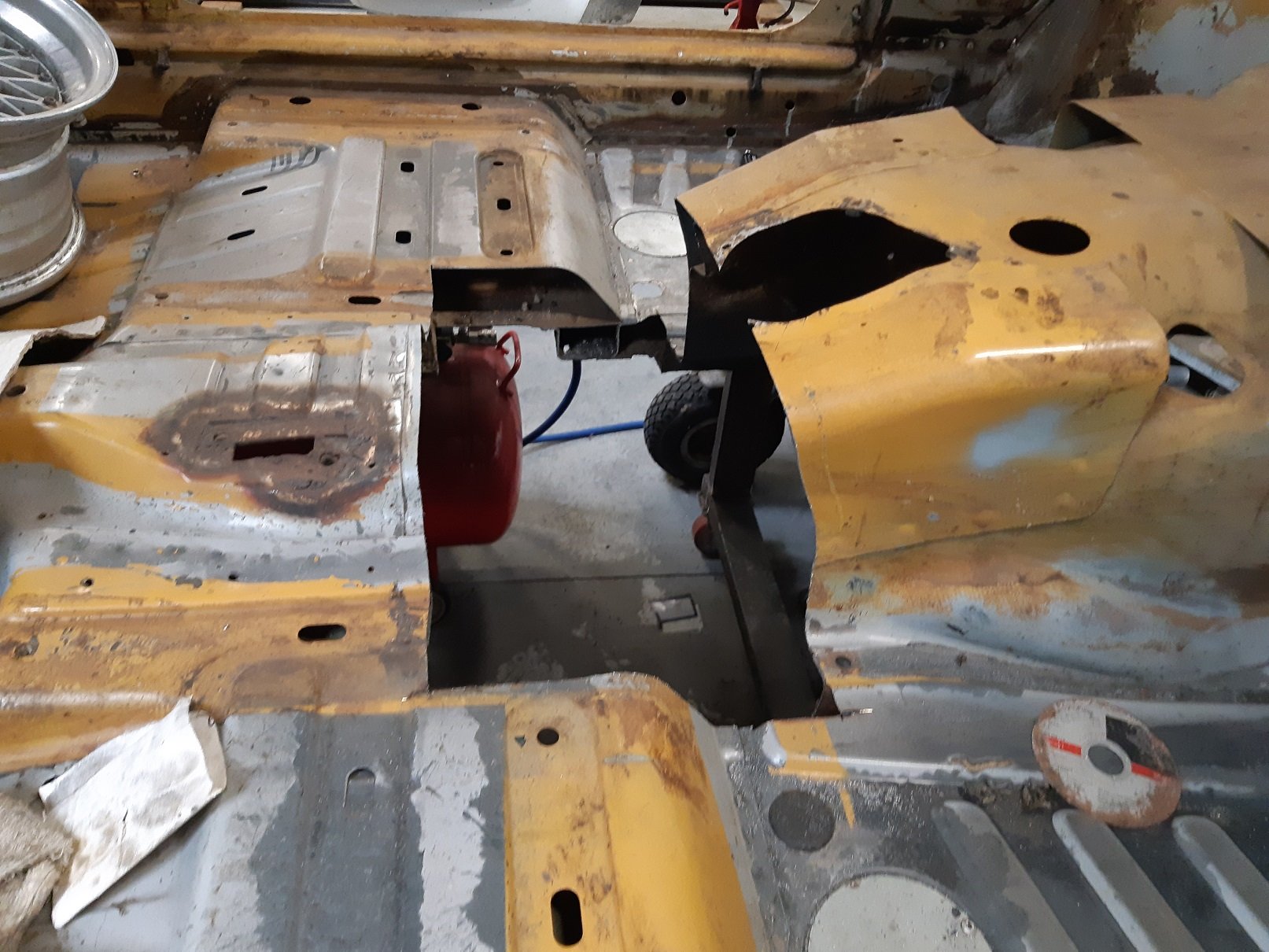
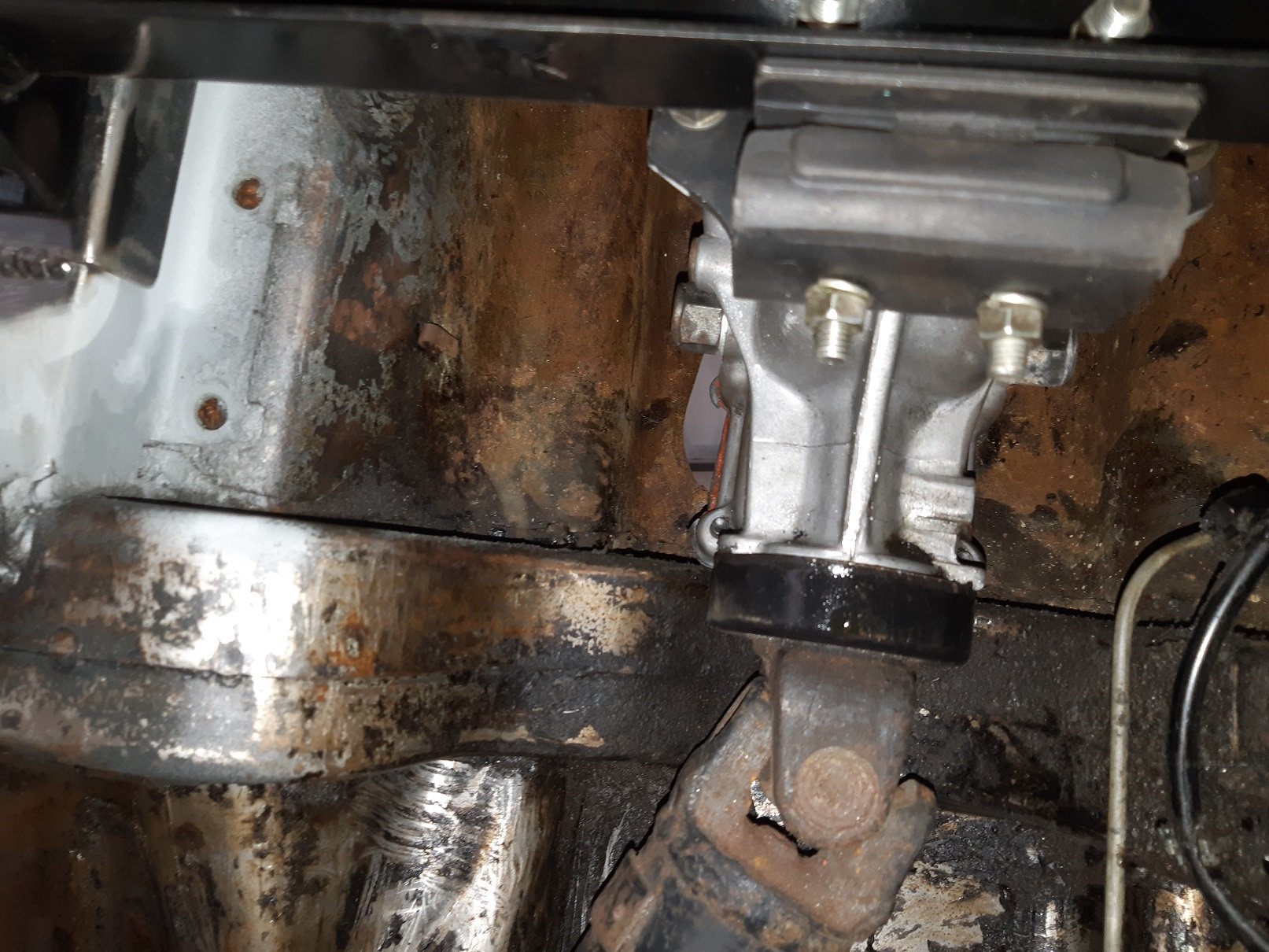
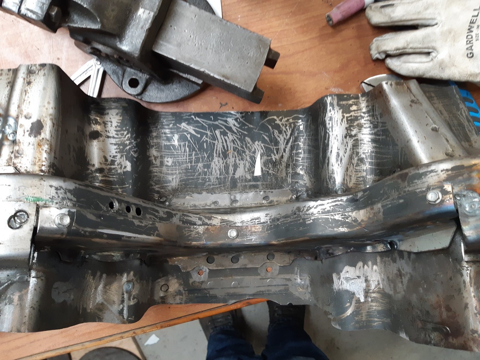
So the shifter housing is real fucking close to the cross member...chassis rail(not really sure what to call it) that goes through the tunnel. It makes it a real bastard to get the gearbox on the engine because you cannot slide it back. You have to drop the engine, and to do that you have to take the engine mounts off. I was going to leave it until much later when I could flip the car over and have easy access. But I decided to do it a different way. I borrowed a piece from the rusty yellow one. Then unstitched the welds to remove the offending side of the cross member Then chopped it up to make myself a puzzle. Then zapped it back together. I started off with the mig, but the welds were such a pain to grind smooth, so I had some more practice with the tig. I made about 30mm more room for the gearbox. I will make the angle bits to join the chassis rails back together when it's on the car. The width of the rails is not consistent, so making them fit this does not automatically make them fit the white one. I'm crossing my fingers that the floor panel pressings are the same.
- 191 replies
-
- 13
-
-
I got some from Steel and Tube seaview. They only do full sheets and don't have the facilities to cut it, so you need a trailer. It was inexpensive.
-
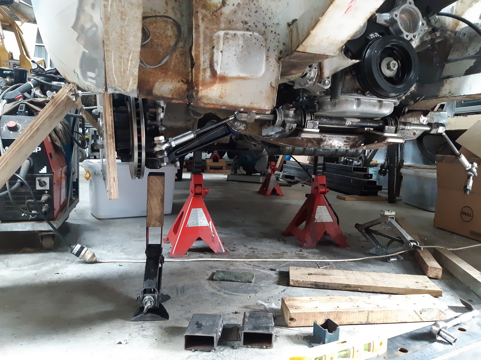
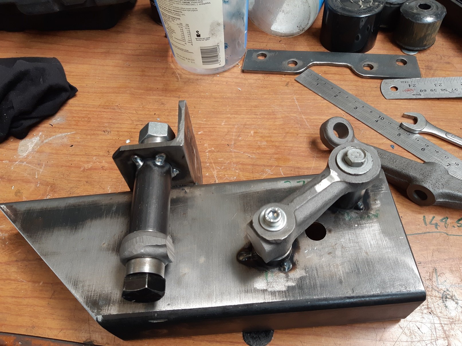
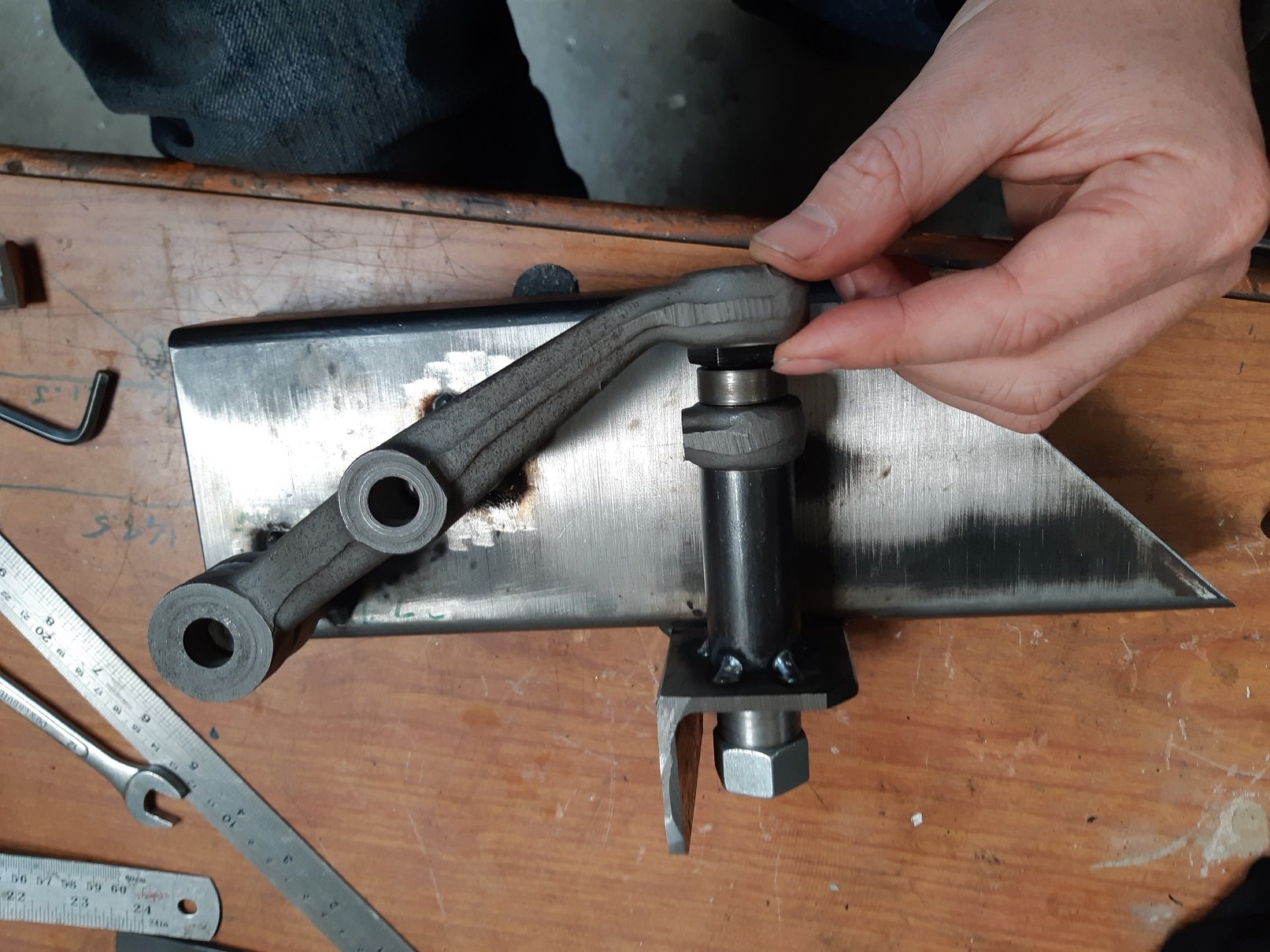
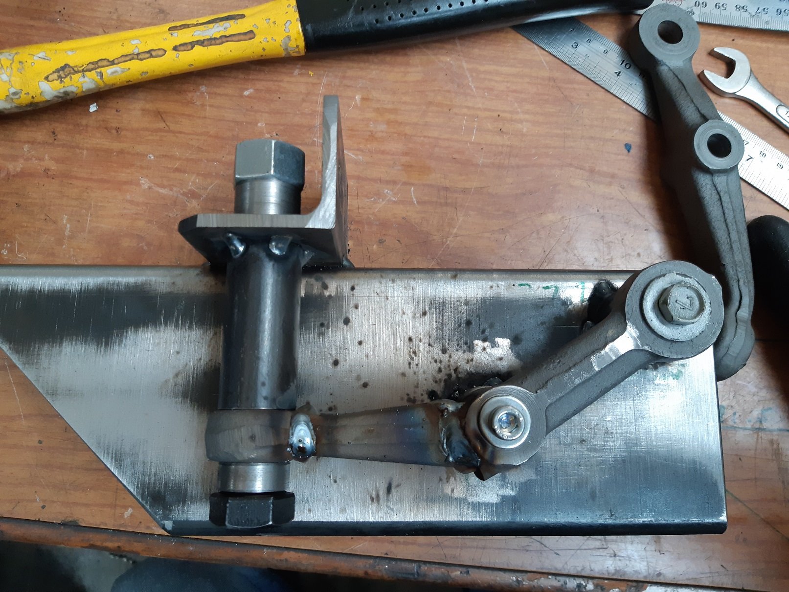
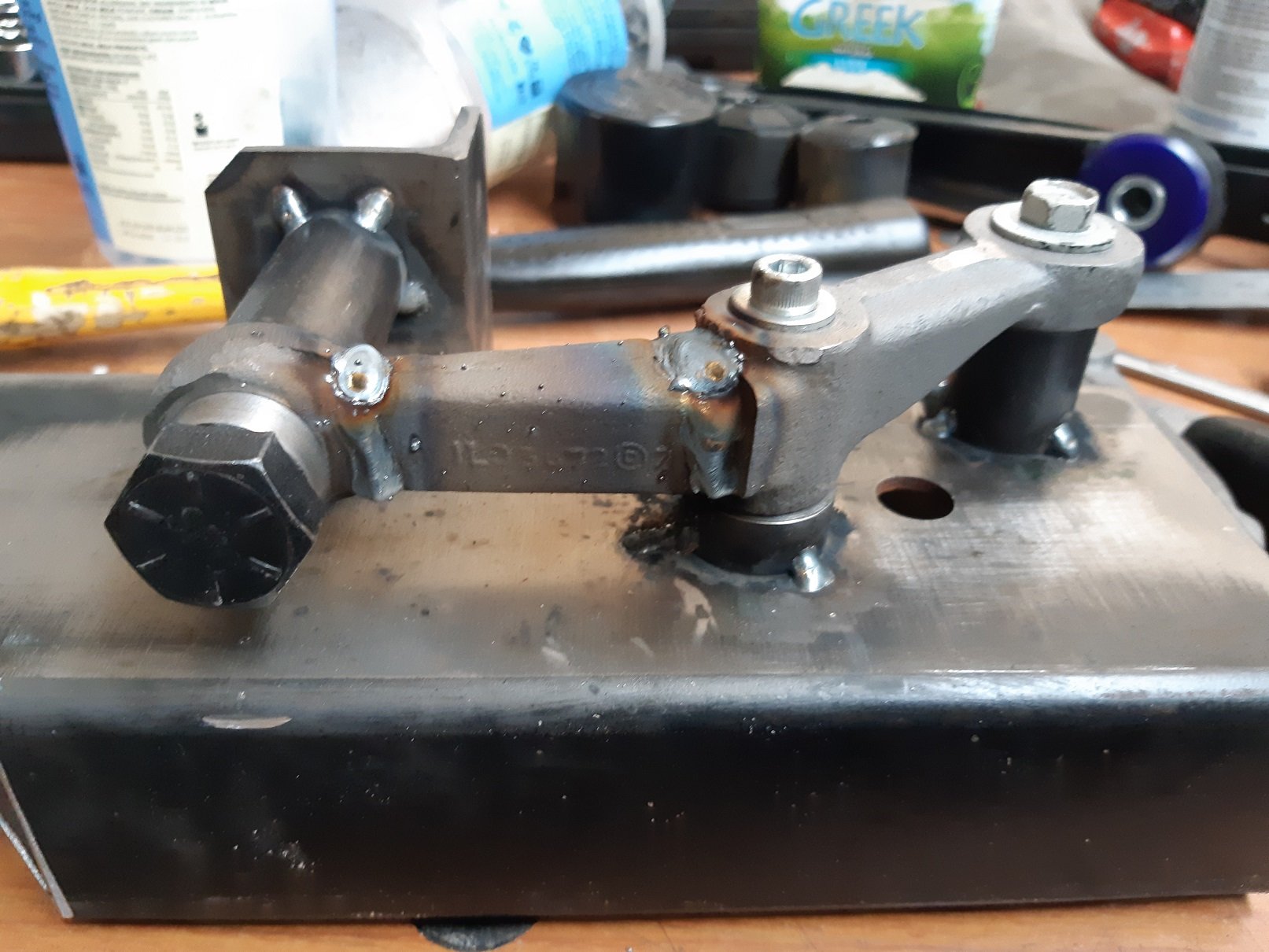
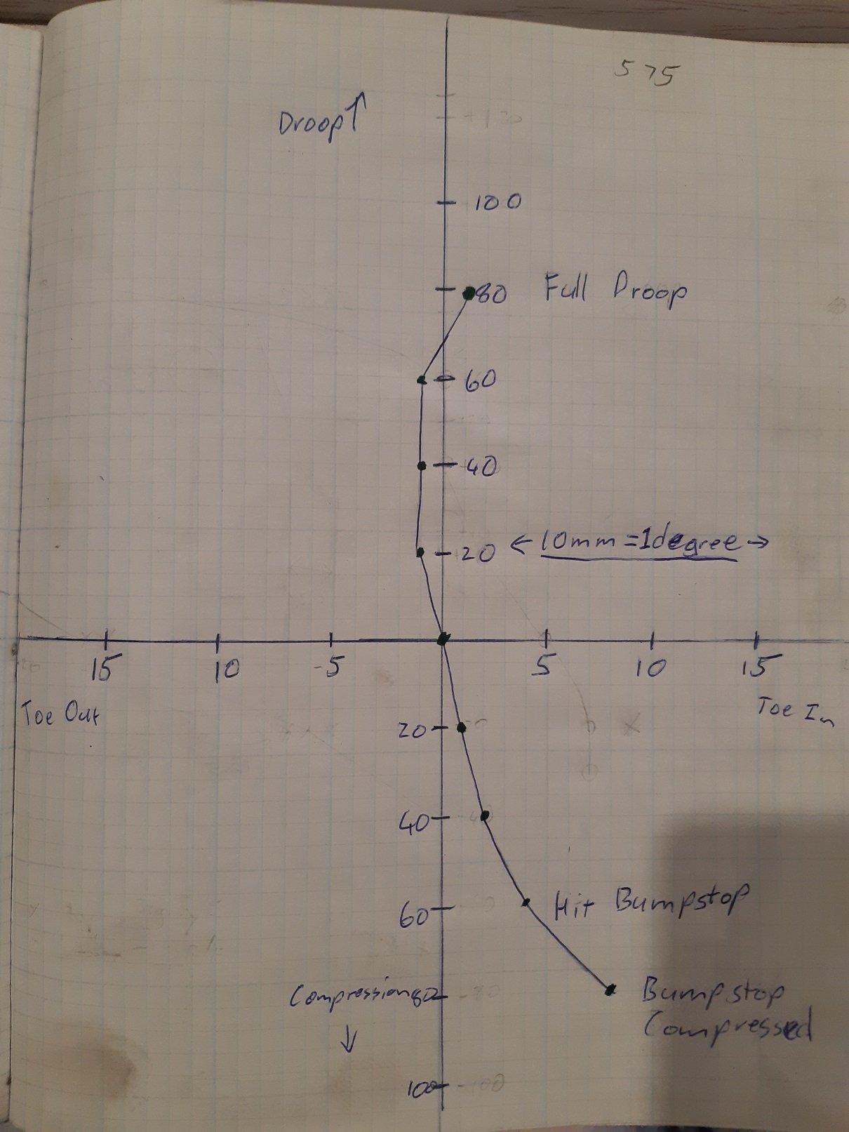
Using my bumpsteer measuring thingamadoodah and fucking around with spacing the tie rod end and rack mounts I found that the tie rod end and the steering arm needed to exist in the same space. So I sacrificed a spare one to modify so I can continue mocking up. I made a jig to hold the end in the right place for welding. Here is the one from the other side to see how far it's moved up. . And totally legit welding. safe as. This is just for mocking up. Once I get the height right for minimal bump steer, I'll mill the final ones out of a block of mild steel and have tapered holes so I can use the factory tie-rod end and not fuck around with rose joints, bolts and spacers. I've been using the LVVTA bumpsteer pdf thing. https://www.lvvta.org.nz/documents/infosheets/LVVTA_Info_04-2010_Bump-steer_Measurement_Background_Information.pdf My measuring thingamadoodah has the points 575mm apart, so each mm of toe is 0.1 degrees. With my hacked steering arm, the tie rod end is mounted below it. This is with a 3mm spacer, it's the best I've got it so far. If I remove the spacer and move the tie-rod end up, the line on the graph indicates the tie rod end is too high. If I have two 3mm spacers, the line says it's too low. I'll have to make some 1mm spacers to see if I can fine tune it further. To flatten out that curve I think the whole tie rod has to be longer, but then I'd need a shorter steering rack.
- 191 replies
-
- 11
-
-
show us your diagram
-
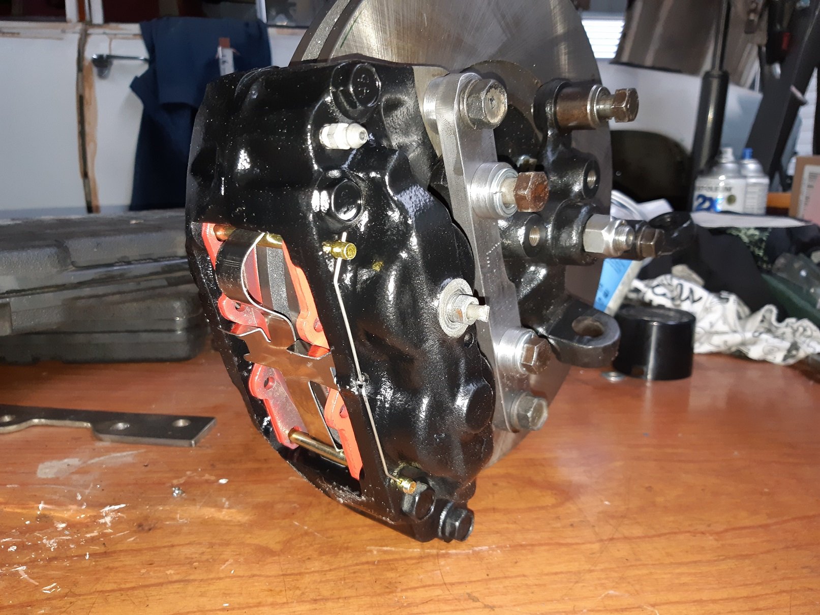
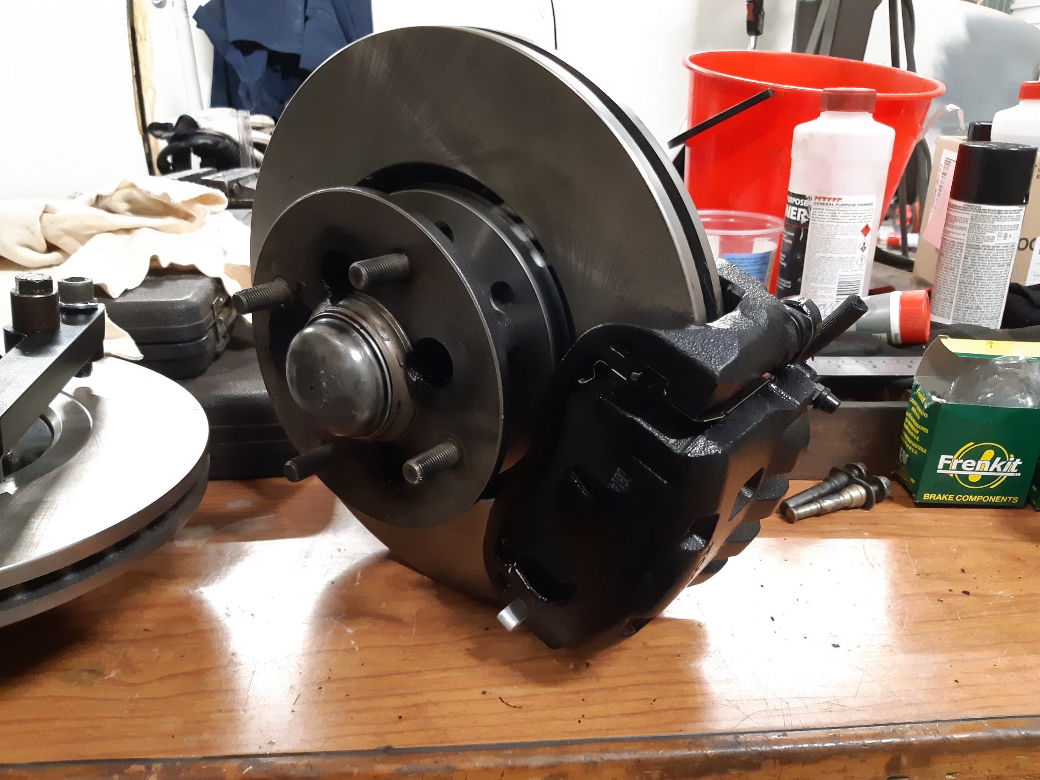
Calipers are rebuilt. I had to use the original retaining spring ring things that hold the seals on as the replacement ones were too short and made the seal bunch up between the ends. I made 3 sets of spacer before I got the thickness right so the disc is in the middle of the calipers. The spacers still have to be tig'ed on and the brackets painted.
- 191 replies
-
- 13
-
-
Have you made a drawing of your wiring diagram? I found it helped when I did my Starlet. AFAIK, yes Diode works just the same in a ground wire.
-
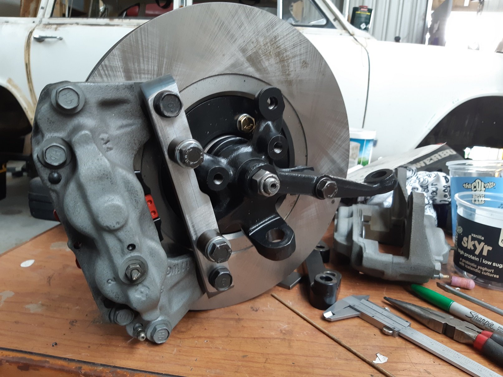
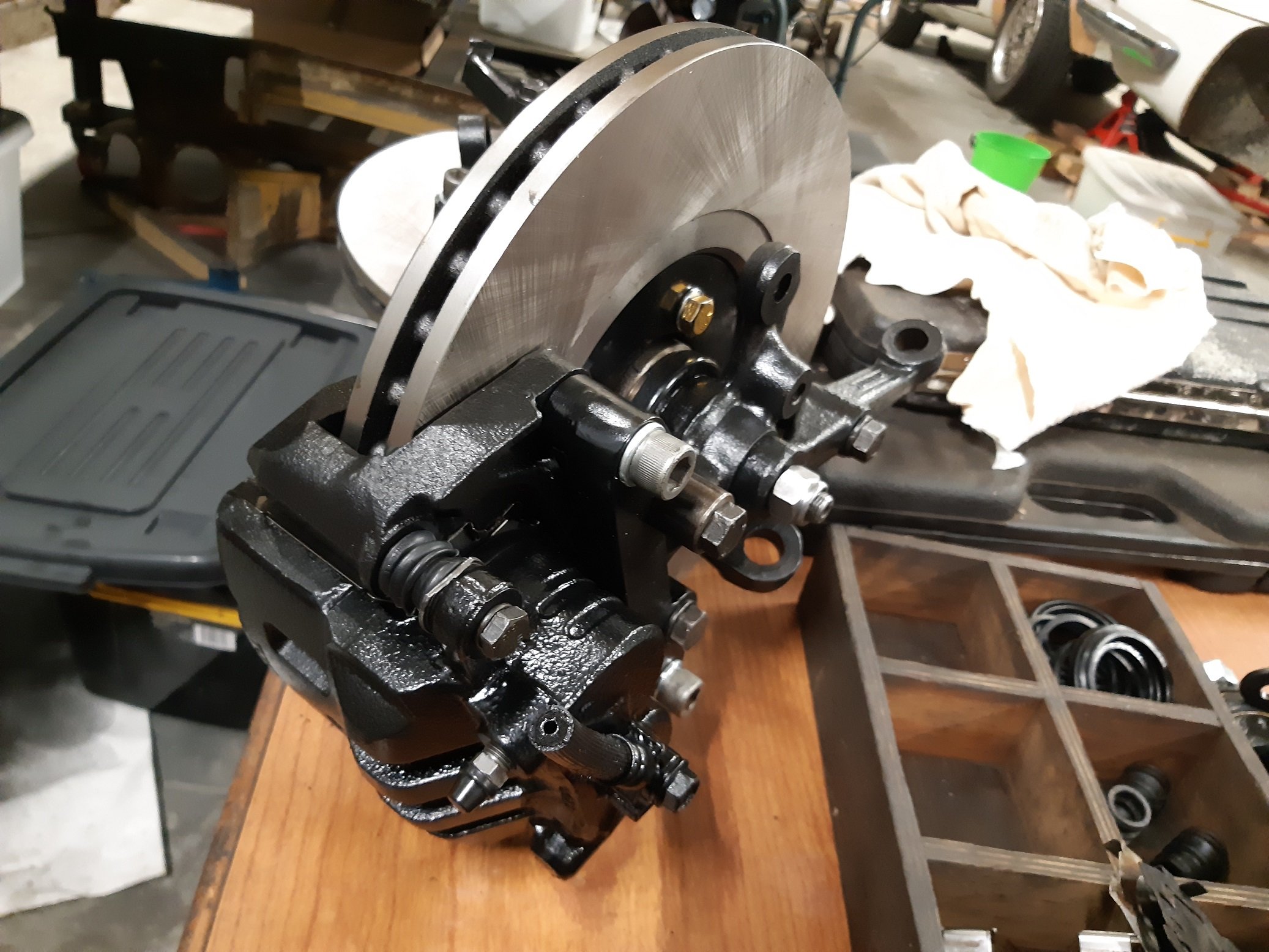
Both calipers are cleaned and painted. I split them before painting to install the new o-rings between the halves. The pistons are good on the outside sealing surfaces, but the inside was a bit rusty, so I wrapped the outside in tape and sandblasted the inside, then painted them with caliper paint so they don't immediately rust again. I'll give them a few days for the paint to harden some more before I assemble them. I've made the caliper brackets for both sides. And all the spacers. I'm going to wait until both calipers are assembled then fit them so I know 100% that the spacers are the correct thickness before I weld them on, just in case. The spacers on the top of the bracket are for the strut, also so I don't need to get shorter bolts.
- 191 replies
-
- 11
-
-
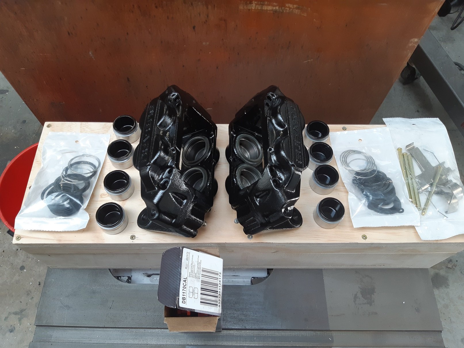
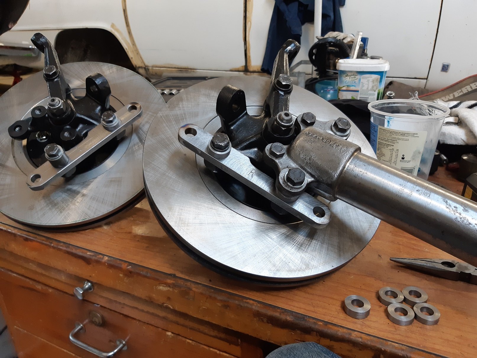
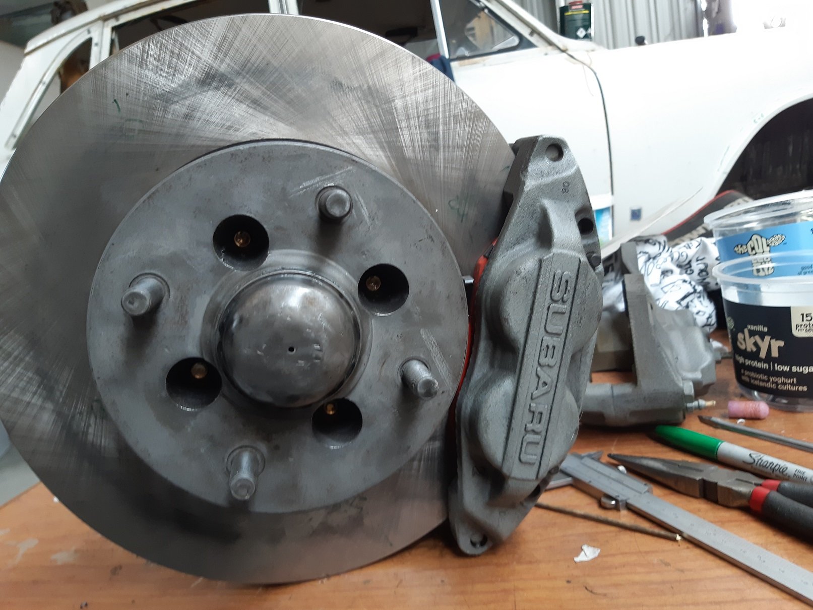
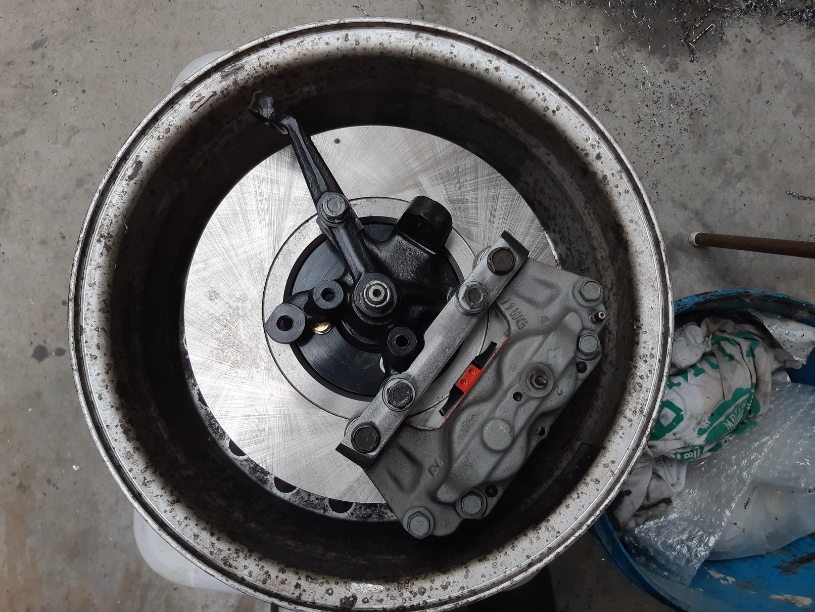
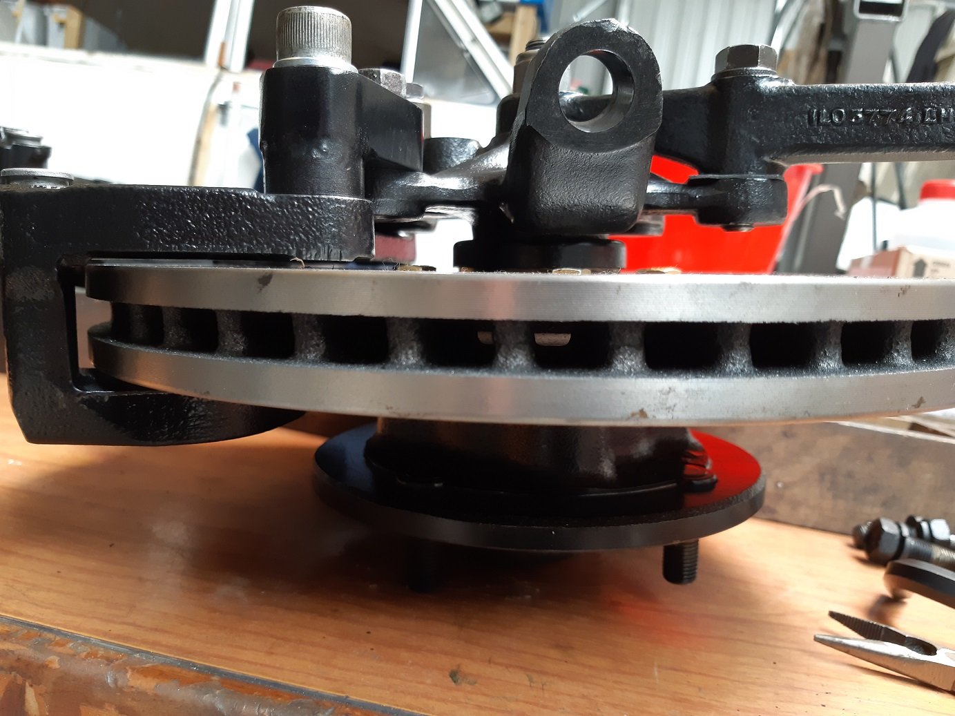
OOOSH... I finally contacted cert man. I've got to get design approval for the rear subframe and the steering rack relocation. He's told me what forms and info sheets I need. I'm not looking forward to trying to accurately draw the rear subframe stuff. But here's some pictures of brake conversion, take two. I went with the subaru WRX calipers. The RX7 ones were much lighter, but too bulky so I'd have to have wheel spacers. All I've done to the calipers is sandblast them and chuck some WD40 on to stop flash rust. I still need to rebuild and paint them. The rebuild kit and caliper hardware arrived yesterday. The bolt holes ended up being all in a straight line, what are the chances... I've only made one side so far, it takes a fucking long time to band saw through 170mm of 25mm thick steel. I still need to round off the ends and make spacers to weld on(it's just got a stack of washers in there now). I freaked out a little when I found I had about 0.6mm of run-out! GOSH!! But I re-tightened the disc mounting bolts and did a better job of adjusting the bearing pre-load, now it's 0.04mm. I'm gonna blame Triumph manufacturing tolerances because I didn't touch the machined face the disc is bolted to.
- 191 replies
-
- 20
-
-
Do you mean having the bolt threads protruding through the other side of the caliper mounting lugs? In my case(from memory, I could be wrong), the threaded hole is tighter at one end so the bolt will jamb and not protrude. I'm gonna assume it's to stop you from using a too long bolt and running it into the face of the disc and damaging it.
-
Yeh. I know I really should. I've been putting it off, I don't really have a good reason why. On previous certs(my Starlet has had 3) I've done all the work and only taken it to see the man at the end. But this project has the added complication of steering geometry from moving the rack and chopping up the rear floor to fit in an also chopped up narrowed subframe.
-
Can I make a brake calliper bracket from aluminium? How thick does it need to be?
-
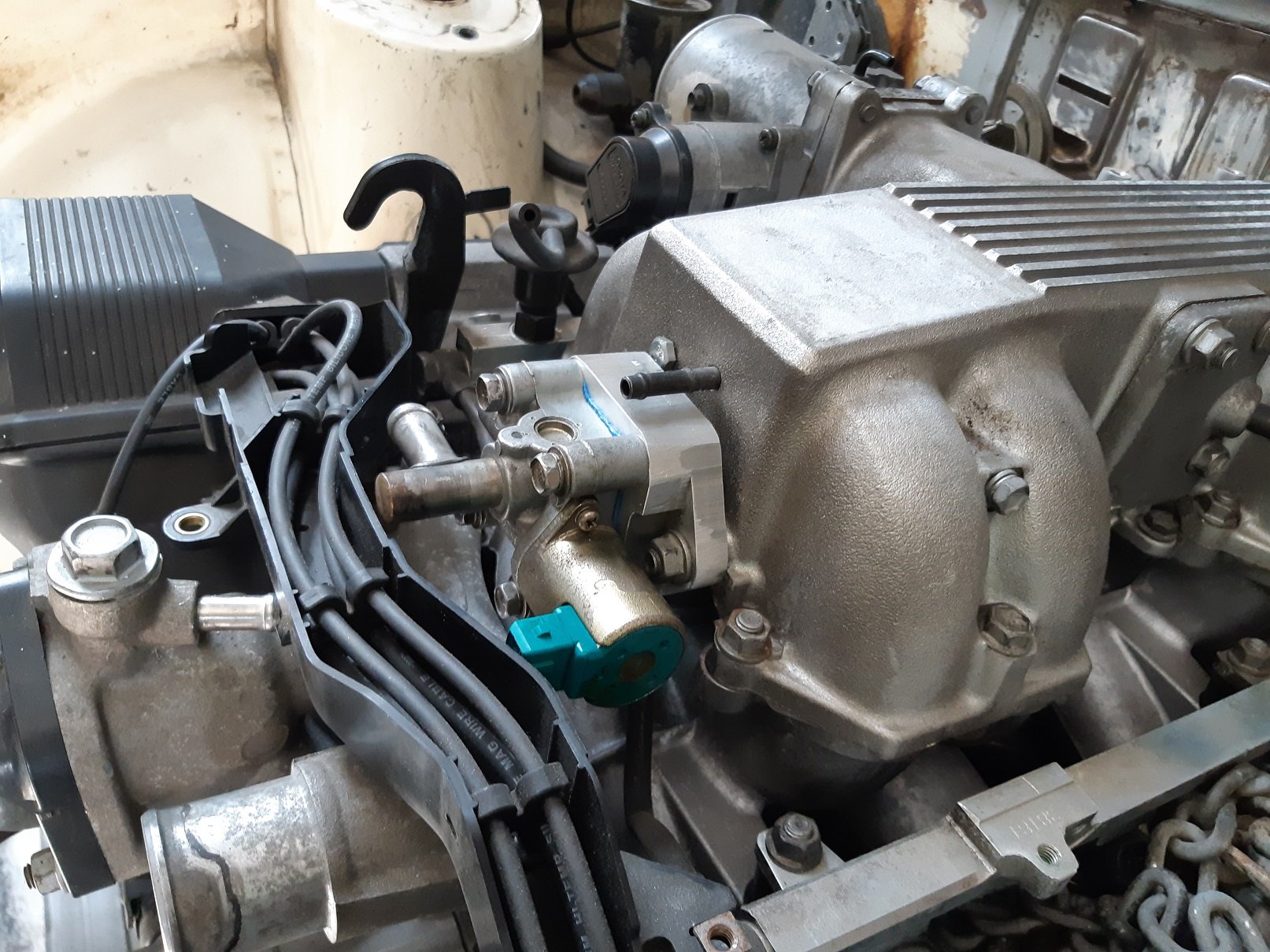
So I bought Sheepers old Link G4. I had forgotten how much the looms cost GEEEEEEZ$$$$$ Since I can't leave shit alone, I decided to change the Stepper motor idle control valve that needs 6 outputs, to a Solenoid idle control valve that only uses 1. I just happened to have a random nissan one, so I used that. I chiselled an adapter plate out of some 100X40 bar. A combination of the 4 jaw in the lathe and the 12mm end-mill in the mill. I could have done a better job aligning the middle hole of both. I had to adjust the hole a bit. First time tig welding Aluminium. Not sure I had the settings right. It worked okay, but looks a bit poo. The cable tray is a bit in the way. But it fits okay.
- 191 replies
-
- 10
-
-
You been watching Jafromobile on Yootuub or something?
-
Just C-Notch your shins at towbar height.
-
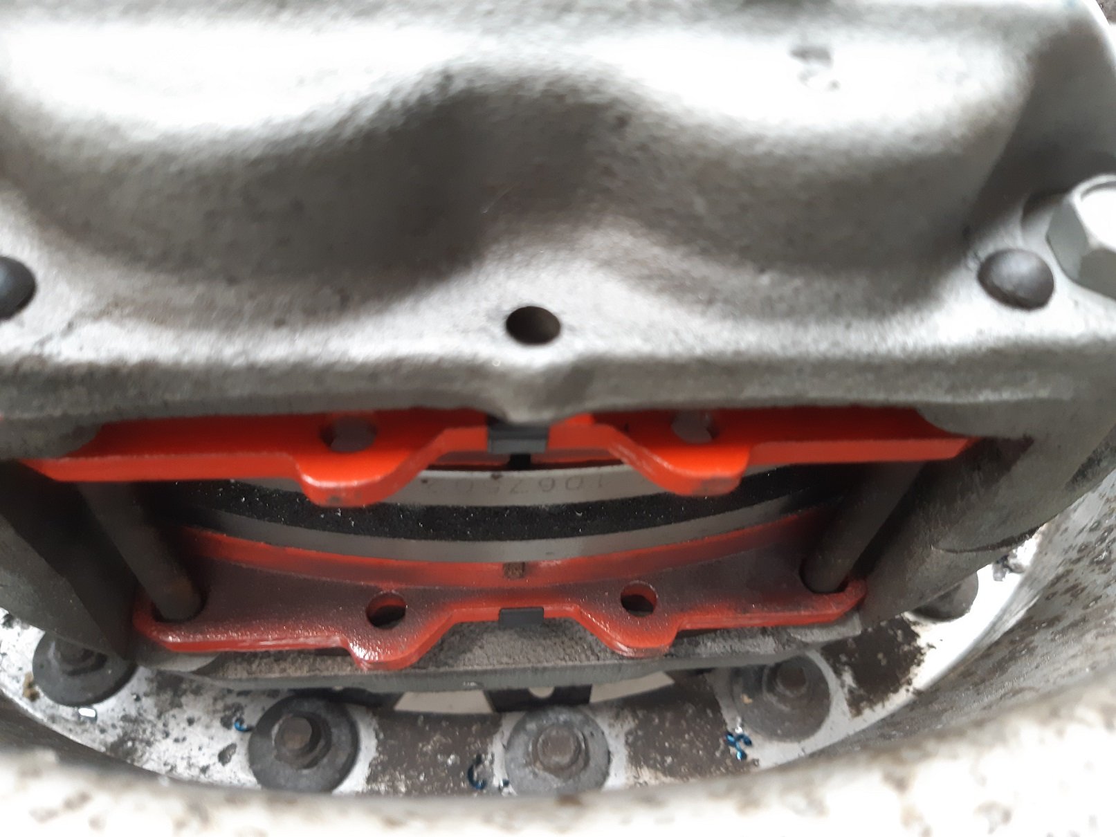
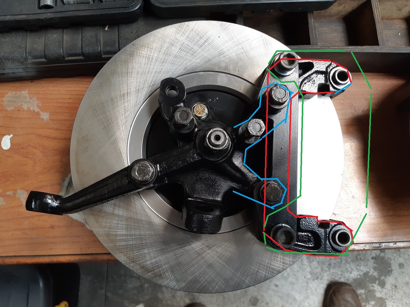
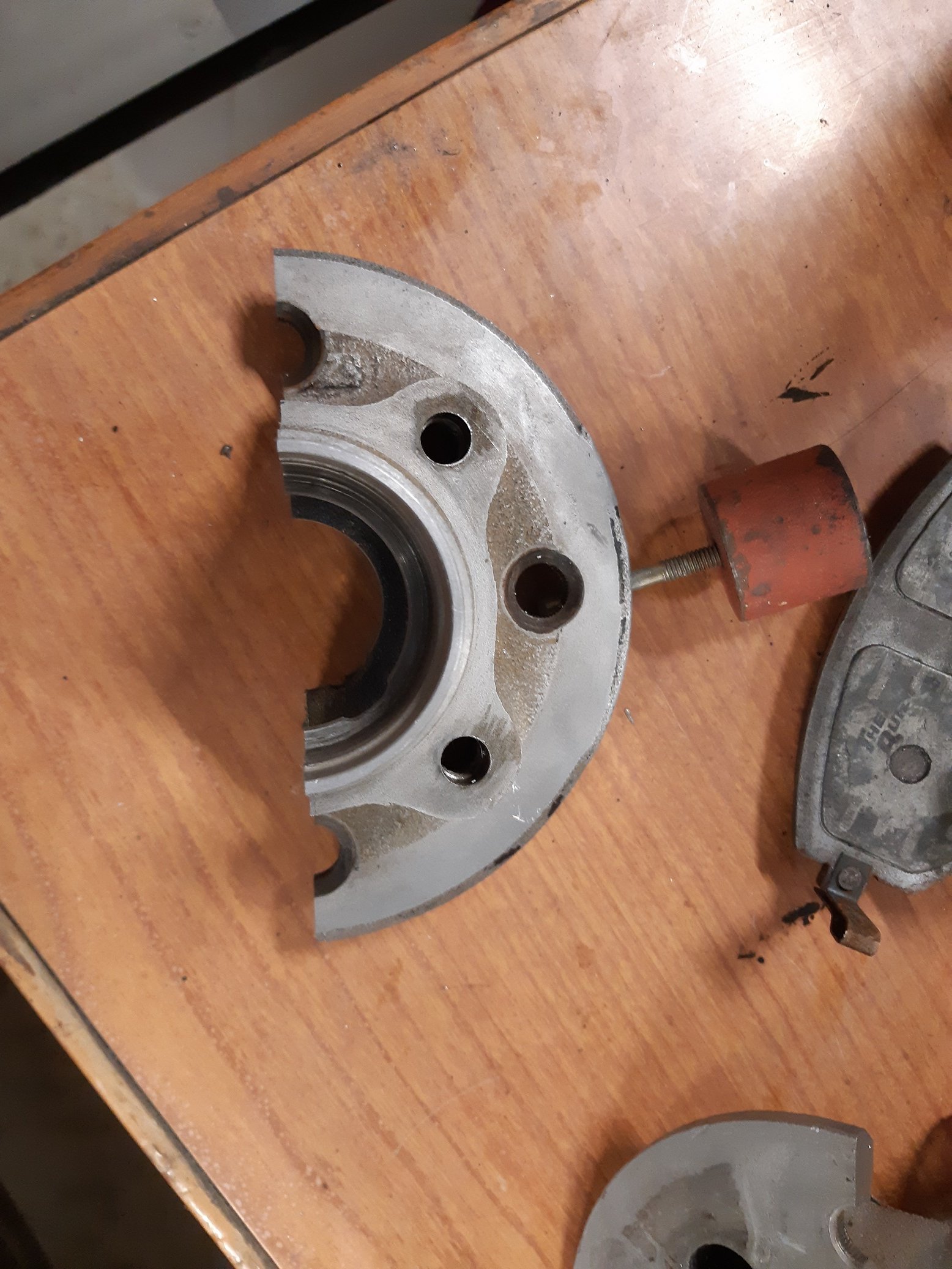
The hub is already machined, so everything fits and nothing hits. But the machining has weakened the hub. With an unmachined hub, the disc sit's 4.5mm further inboard. The subaru caliper bracket(red) is underneath the mounting lugs(blue) on the upright. There is only half a gnats nut gap between them. My adapter plate ties them together. For the caliper to line up with the disc 4.5mm further inboard, the blue and red have to merge inside each other. The green line, AFAIK, is how the 4 pot WRX caliper would fit, the red bracket is no longer needed(I still have to get a hold of one to measure). But it might be the solution to my problem because there is nothing in the way of moving it inboard. But "WRX" = $$$$. EDIT: This fopar happened because when I was mocking up and measuring, the upright I used had a small ridge on the spindle and the bearing wasn't properly seated.
-
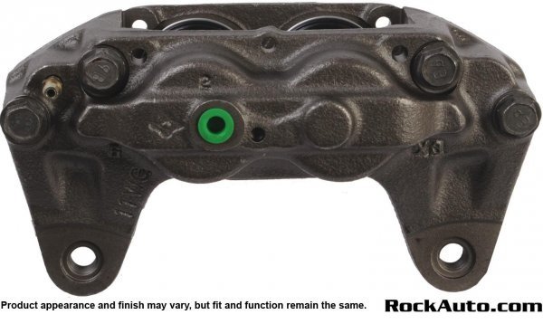
So it turns out machining down the mounting face has weakened the hubs.... Cletus said he'd fail it. Waaah I cut a spare/scrap one in half to check. So the options I see so far are. Make new hubs from scratch. Which will be a lot of machining with plenty of chances to turn my part to scrap if I make a mistake. Or, get some WRX 4 pot calipers. Because they don't have a mounting bracket that interferes with the mounting lugs on the upright and that would allow me to move the caliper inboard to line up with the disc in its previous location(before I machined the hub). AFAIK the mounting hole spacing will be the same as the current calipers, so I can modify my existing adapter brackets. The WRX ones look like this.
-
I can't, the caliper mounting lu gs on the upright would occupy the same space as the caliper frame thing. It looks like you could move it in the photo, but there are raised ribs in the way. One possible option could be to use Subaru 4 pot calipers(only from WRX??), if I can find any for not stupid money. AFAIK the mounting bolt distance is the same on all calipers, but since the 4 pots don't have that bracket, they only have mounting lugs, I should be able to move the caliper back. This option might possibly cost less than the materials and time to make custom hubs.
-
Dang it. If i were to machine some hubs from solid. Do i need to get design approval first? Do i make them from cast iron, or steel, or could i even use aluminium?
-
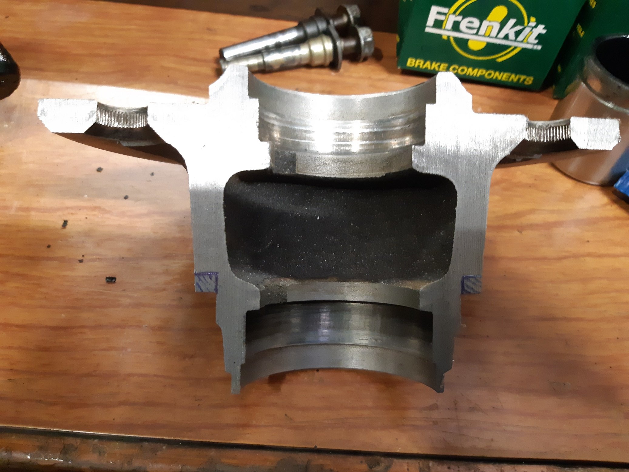
Cert/brake modification question. So maybe you have been following my triumph project thread... For my front brake conversion I machined down the back of the hubs where the discs bolt on, by 4.5mm, to get the disc in the right place in relation to the caliper. Some times after doing that I realised that the interior diameter of the hub is larger in the middle. I was slightly concerned that machining the disc mounting face might be close to breaking through to the interior. I had a spare hub, it was scrap because I machined the disc location diameter undersize..... Soooooo I cut it in half with the band saw. I've drawn in the 4.5mm that has been removed. The thickness has gone from 6mm to 3.5mm. How thin is too thin? The disc is bolted to the wheel side of the hub so I don't think that area is loaded during braking. Is this going to be okay/safe? What would @cletus say?
-
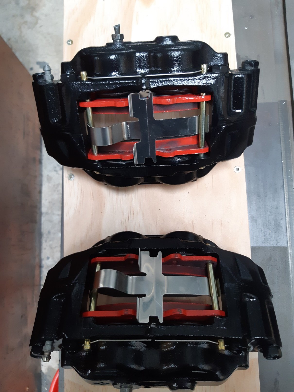
And I got the rubbers on my way to work. Thanks Greg at MPAutoparts. It wasn't cheaper, but I get instant gratification, and I'd rather give Greg money than 'Murica. I rebuilt the calipers after work. I dunno, but with the rubber gloves and the lube and the rubber parts and trying to fit things where they just don't seem to want to go, but then they do and it feels good, rebuilding calipers just seems slightly lewd. Here's the left one, I'll let you imagine the right one, or you can just look at your screen in a mirror.
-
I've also cleaned and painted the calipers. The pistons can be reused, but the rubbers are knackered, so I've got to get a rebuild kit before I can assemble them. They are 2003 Subaru Impreza 2 pot calipers. The rebuild kit from rock auto is really cheap, ~$17 with all the springy plates too, but freight is about $40. Surely I can get a rebuild kit for less than that locally?