Roman
-
Posts
7,223 -
Joined
-
Last visited
-
Days Won
39
Everything posted by Roman
-

Daves new school holden shambles. (Is this project oldschool yet?)
Roman replied to Muncie's topic in Other Projects
Can confirm that it looks mean. -
Adrenalin R sells packing material by itself. But it's just rolls of stainless wool as well I think.
-
Well, need to keep in mind that they're not spring chickens anymore! An R32 GTR is now as old as a Mk 2 escort was, when this site first started. Any car of this vintage can be really nice if you're lucky, but is likely in need of some repairs and maintenance. It's funny though how your brain can still think that cars like this are new-ish though. Gone are the days of "Is my car oldschool if it has plastic bumpers" Now we're on to "Is my car oldschool if it has Advanced Total Traction Engineering System with Electronic Torque Split - But only the early version?"
- 129 replies
-
- 20
-

-

-

-
It seems more likely that a VVT pulley would be the first thing to go. There have been some failures even with standard 2GR motors. But you get lots of notice as it will rattle on cold starts if the pin isnt engaging. Or otherwise having a rocker fall out. Someone said that Toyota revised the valve springs to a beehive type to address the issue that the earlier motors had with firing the rockers out occasionally. However I'm not sure at what point that changed. Although, a lot of these things are a non issue if you're keeping to factory rpm limit, for the better part.
-
Yeah these have super grunty 6 bolt main bearing caps. 2 more bolts come in through the sides of the block. But there are two rods between each bearing cap. So win some lose some, I guess. I figure this is one of the cases where the modular nature of these motors works in my favour. As it's all setup to be strong enough for the 3.5 (or arguably 4 litre) versions of this engine. So I'll have some more spinny forces going on, but nothing near the loads people are throwing at boosted 2GRs making 700hp or whatever.

-
Ahhh right. I'm not too sure, a friend just had one in their stash for whatever reason.
-
Wiki says: So not hugely common. But still cheaper and easier than sourcing a 5GR crank from China. I'm glad I've got one set aside for me already, so I can see if it will actually work.
-
The rockers and hydraulic lifters, vvt pulleys and lots of other bits are all exactly the same between all of them.
-
This is fucken excellent
-
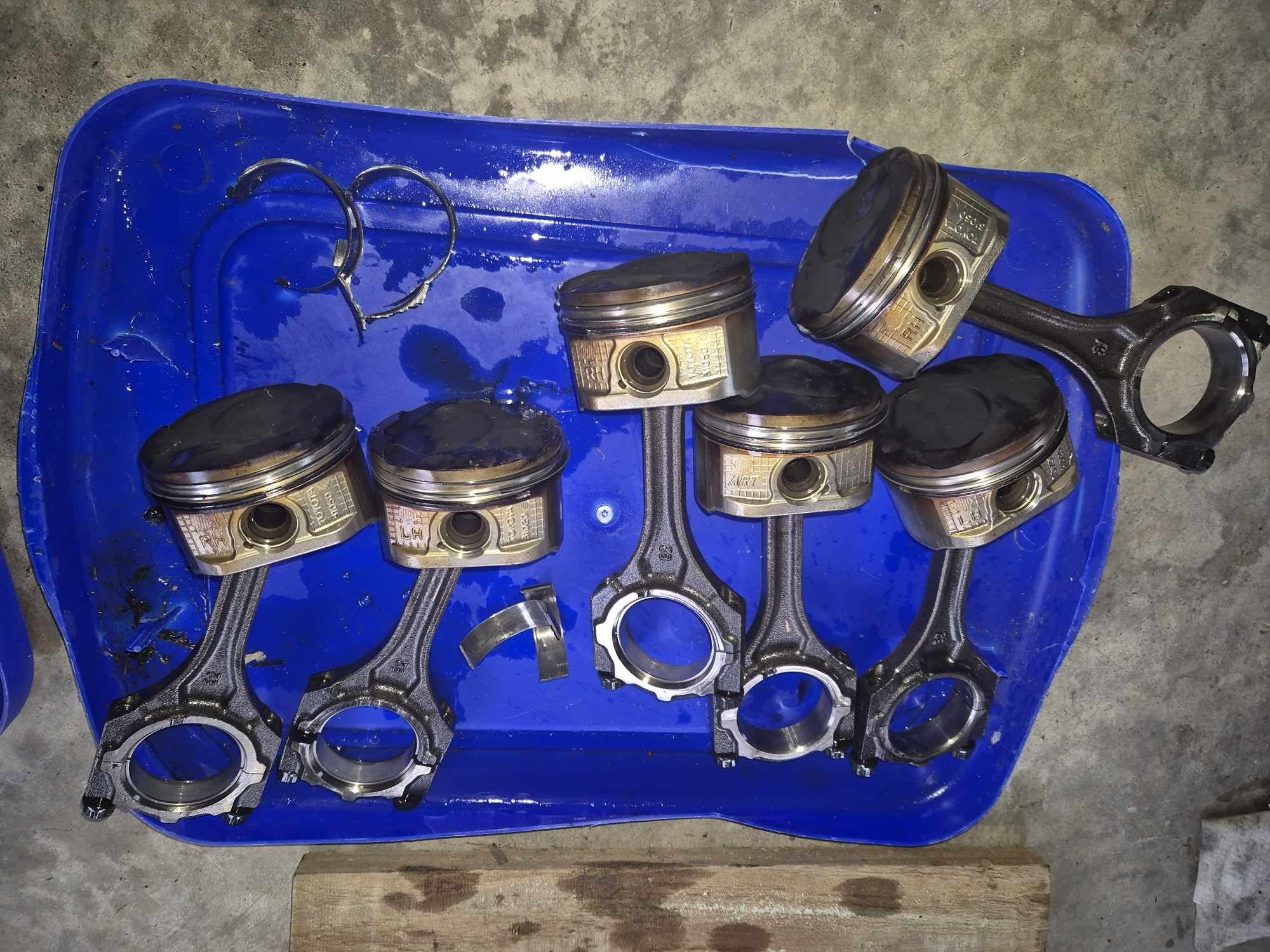
I wont have another 4GR motor until at least the end of Feb. However in the meantime a very cheap FWD 2GRFE came up. It was missing a bunch of stuff, and it looks like it's never had an oil change... This was a good buy for a few reasons. One of which is to be able to compare the cams. To 100% check if aftermarket Kelford cams will fit the Direct Injection engines. So all of the dimension etc are the same, phew! Just nothing to run the (now removed) DI pump. This motor also has the bellhousing pattern that is similarish to the 3S - So I can see how an Altezza bellhousing will fit. Then I can see if it would have actually bolted up how I was intending at the start of this project. Something else that I have confirmed by pulling the 4GR further apart. Is that the 4GR does indeed have exactly the same length conrod as the 3GR and 2GR. So they are all 147.5mm center to center. The motor deals with the reduced stroke length by adding more compression height to the top of the piston. To account for 6mm stroke difference, the piston only needs to be taller by half that much. So ideally it would have a longer rod. But it's good news in that the plethora of existing forged 2GR rod options will fit any of the motors. For research and dissection purposes. A friend is dropping off a 2MZFE to my place, some time in mid February. (Thanks Adeel) This is the 2500cc V6 from the previous generation, that has the shortest possible stroke crank that might fit. It has a 69.7mm stroke, same as the China only 5GR motor. The crank appears to be identical dimensionally to GR engines, apart from having a different part slotting onto the nose of the crank for chain vs cambelt. This will be the cheapest and easiest way to repeatably source a sub 70mm crank. So, keeping in mind the above. It's actually some cool news that all of the GR motors have the same length rod. Because if I design and make some conrods to work with a destroker crank. The same rods and crank combo will work with a 2GR, 3GR, or 4GR. With the short crank and longer rod you get: 2GR: 2800cc 3GR: 2500cc 4GR: 2200cc Then it also means that any aftermarket forged pistons, currently available for a standard length rod. Will work with the destroker combo. So for only doing 1 job it unlocks a lot of options. A 69.7mm stroke engine reaches 5000 ft/min (Same as Echo was doing at 9000rpm) by 11k rpm instead of 10k. Or more to the point, 10k rpm would only be around 4500 ft/min which is quite a conservative max speed. Not that any of this matters if the heads want to blow to smithereens well before that. Onwards with the meaningless suffering
- 131 replies
-
- 45
-
-
-
Discuss here about Yoeddynz's little Imp project...
Roman replied to yoeddynz's topic in Project Discussion
...You reckless bastard! -
The longer term plan if the 4GR goes well, and there arent any insurmountable issues. Is to get a 3GR and then put a 2MZFE crank in it. This gives exact same bore and stroke as a 5GR, but uses parts that are a bit easier to source here. A friend has a 2MZ for me in storage, and there's a few 3GRs at pickapart at the moment. However it looks like the greater difficulty, well before the current stroke length is a limiting factor. Is getting the valvetrain to play along.
-
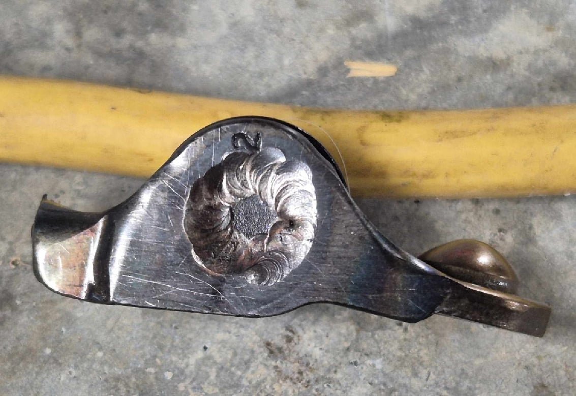
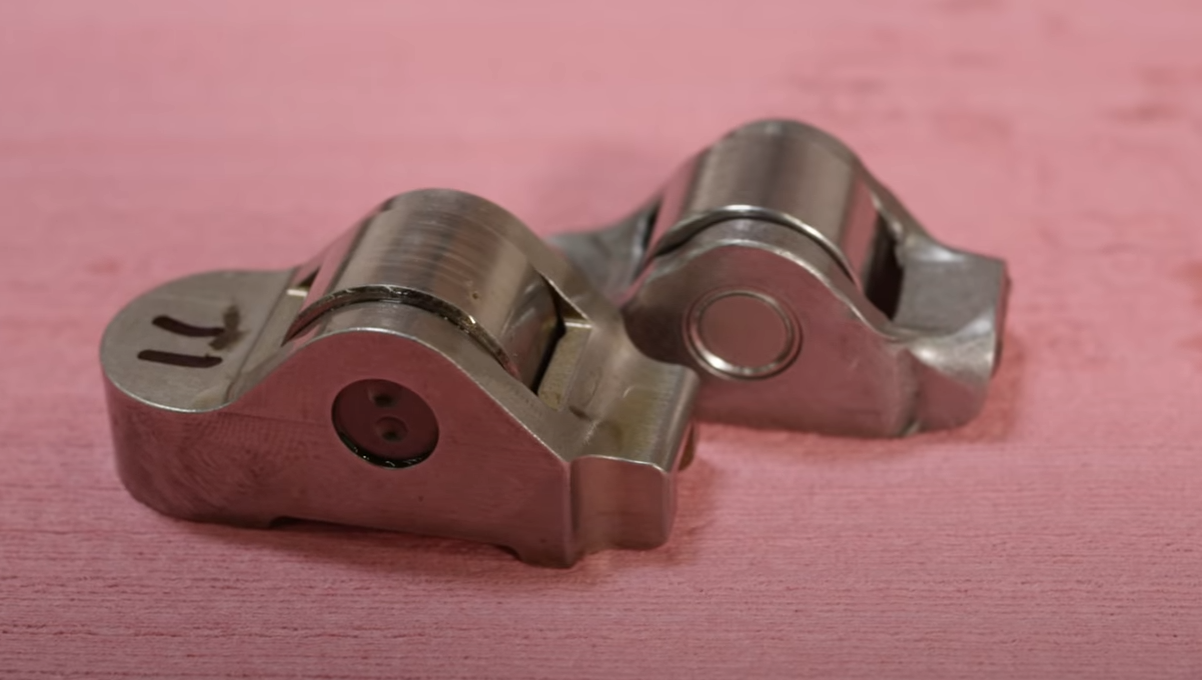
Regarding the rockers and welding them. Since they take a hammering I'm concious of doing stuff that will make the metal brittle or whatever. So what to do? Was initially thinking a few small tacks each side. But since the weld area is actually tiny, because these parts are tiny (thats an extension lead in the background) I figured I'd fully weld one side, and leave the other as is. So if it needs to move, it can move. rather than welds both side shrinking as they cool and trying to pull the pin from both ends. Then cracking or whatever. It's probably all splitting hairs anyway. You cant really tell from the pic, but the weld pool is very shallow, it's only sayyyyyyy 1/10th of the way into the rocker. But I now have 23x rockers that are one side welded. All of them turn freely and seem fine. All I need now, is a 24th rocker. And an engine to put them in. Haha.
- 131 replies
-
- 31
-
-
I didnt realize that was an option! Keen as
-
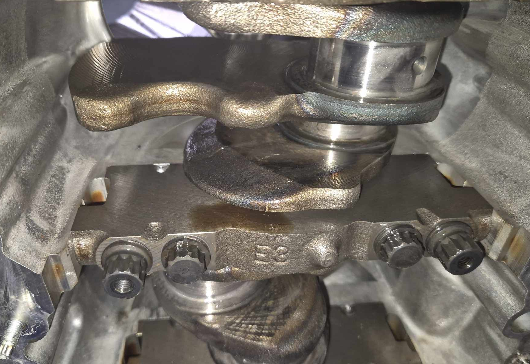
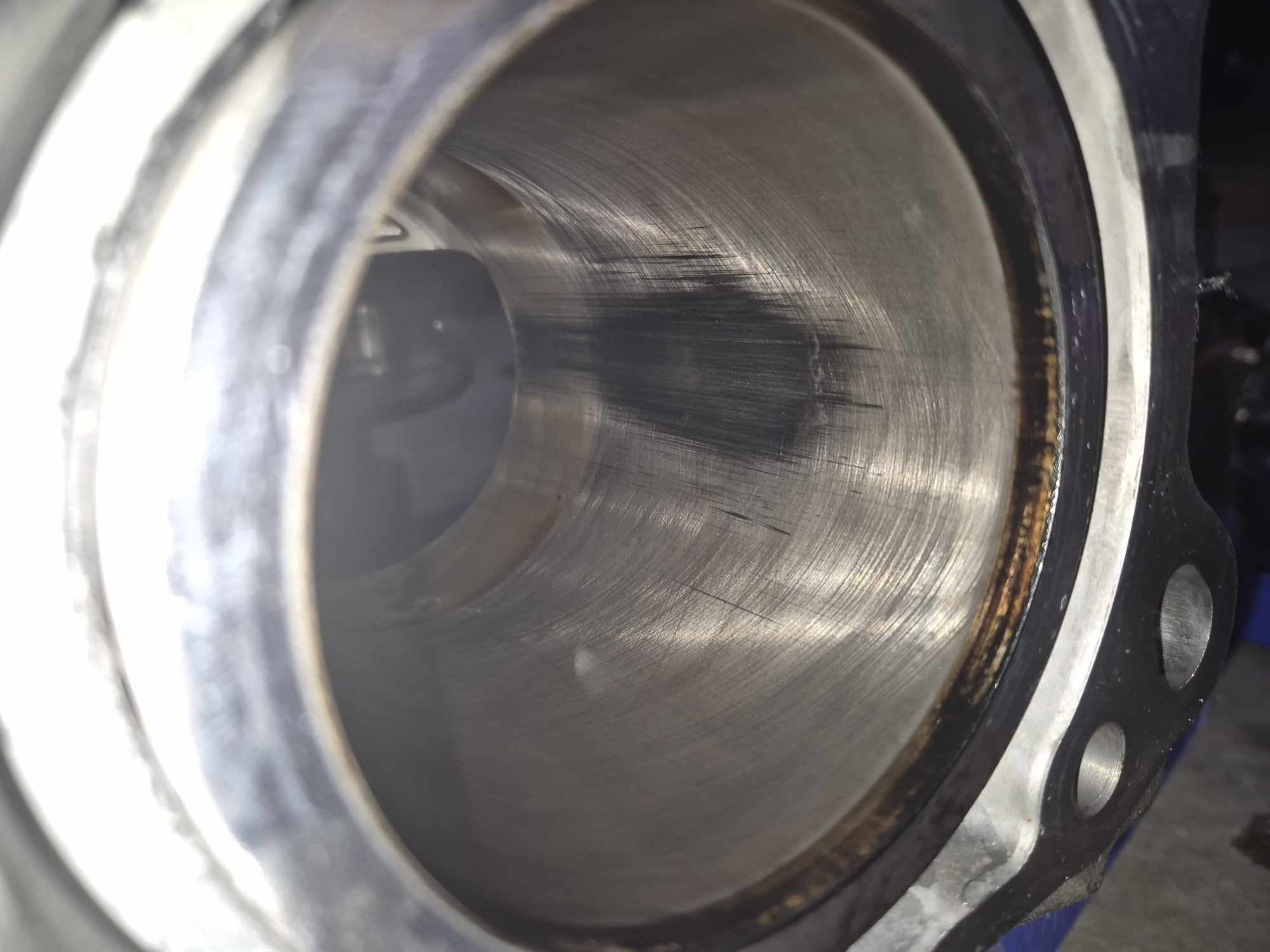
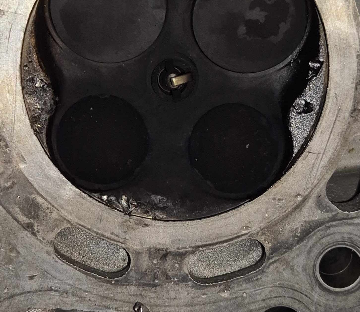
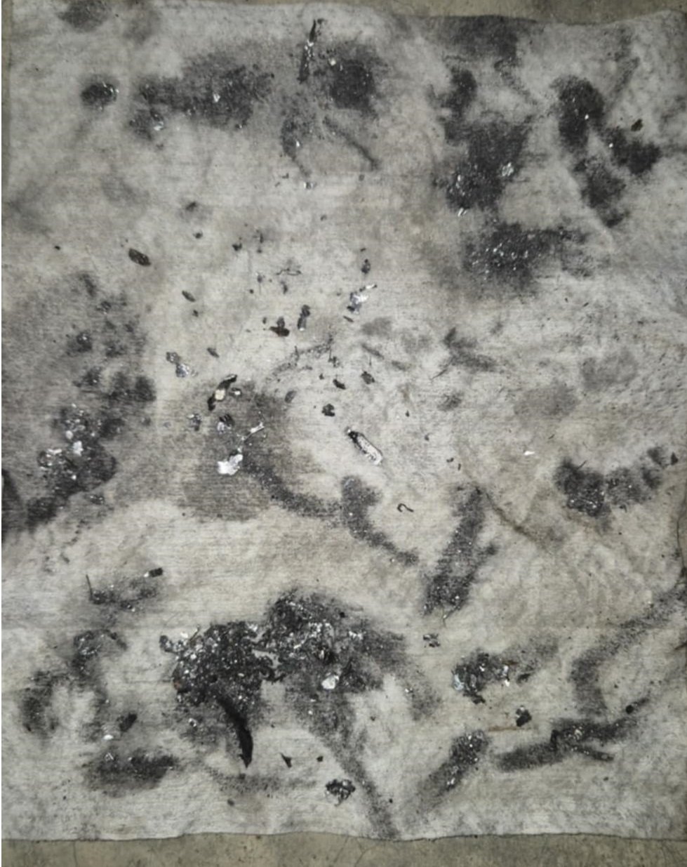
I found the cause of the debris field. Two rods on the "bent valves" side of the engine, had essentially vaporized their big end bearings. So this motor is definitely off to spare parts heaven. Haha. Some interesting evidence is showing in the bores on that half of the engine. Of the forces put on the pistons to bend the valves. The piston coating has all been scraped off on the exhaust side only. Which I guess makes sense given that only one side of the piston (the other side) was conked really hard by the valves, pushing that side into the bore. Ahh well, feels good to know for sure what happened now. I am looking forward to getting the new motor and making a start on it!
- 131 replies
-
- 32
-
-

-

-
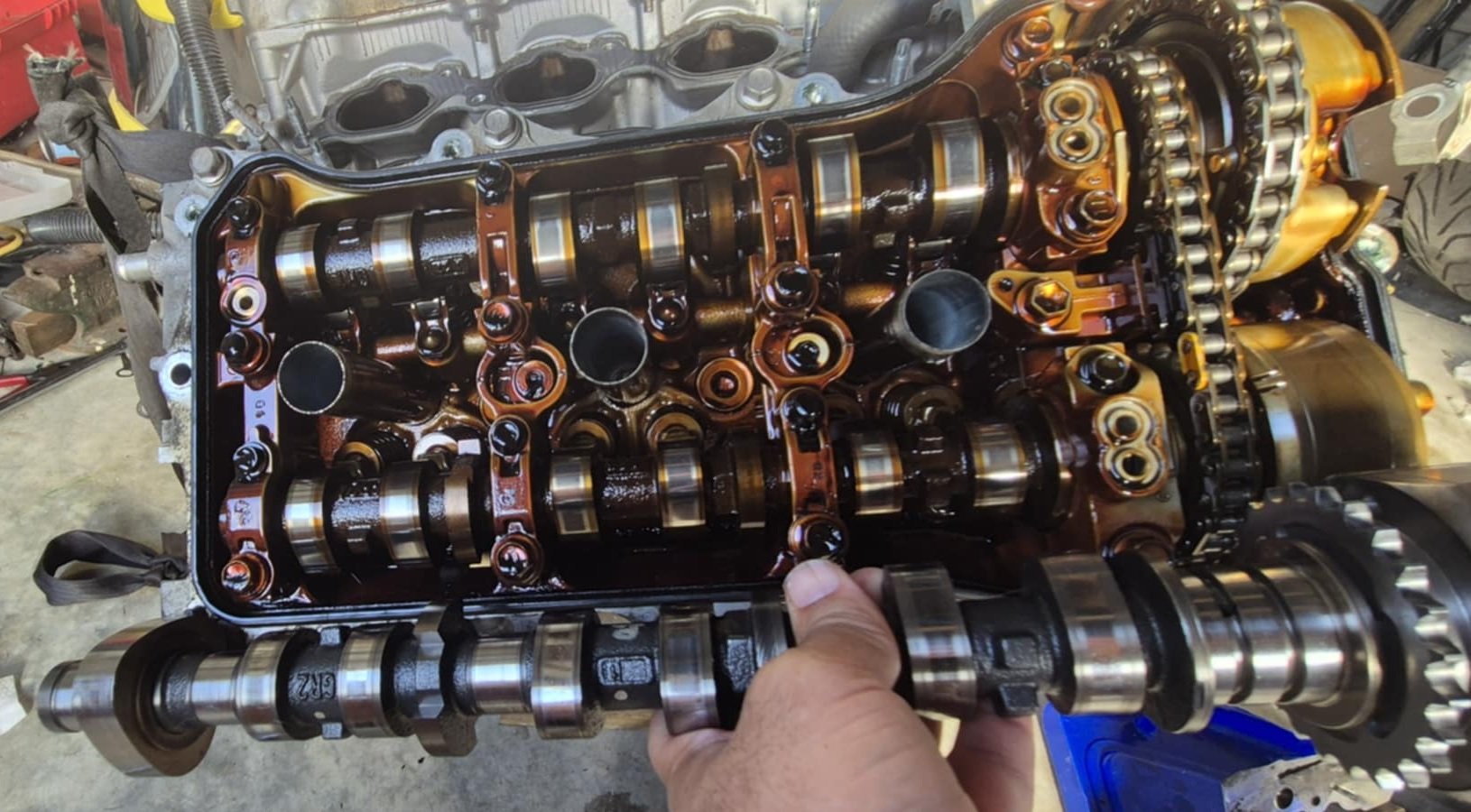
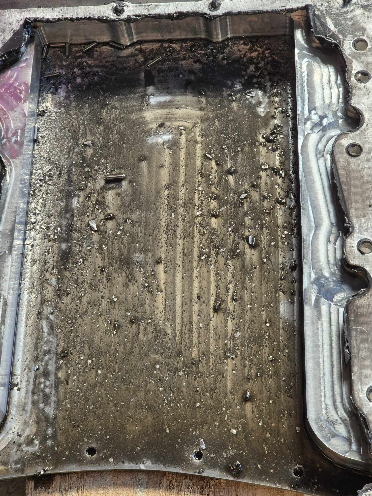
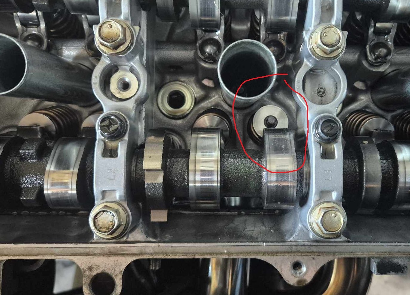
I got the head back off tonight. The combustion chamber etc, all looked perfectly fine. I tried hammering the valve out, and it just snapped at the bend - so the rest slid out the bottom. Easier than expected! However the valve guide was already broken off at the top, and cracked further down. So it would need repairs to keep using this head. Taking the rest of the sump off, and there's definitely a whole bunch of shit in there. I am still not sure where it's come from yet, as there's no damage to the rocker/cam/anything up top that can explain the volume of material that is present. The worst damage that I've found apart from the valve/guide, was actually on the next cylinder over. From a previous incident. Where some crap had fallen in, however that happened. There were a few dents and a few pieces still lodged in. The piston looked mostly okay. I thought I'd dodged a bullet on that one, but it probably would have caught up with me. It would likely be a lot more prone to knock on that cyl. As some of the embedded bits might act as hot spots. Which isnt a great thing given the high compression ratio already. It's borderline tempting to just try clean this all up, replace a valve guide and reuse the head. But this poor thing has taken enough of a hammering. Lots of accumulative damage by now. Even if the big end bearings arent already toasted, they've probably had a hard time from when the valves all bent. So this can go on the engine stand as an R&D/spares motor. I had a look at all of the other rockers, to see if there were any other signs of the stakes failing. There was 1 more which looked like it had had the pin had started shifting across. But not quite enough to dislodge yet. Swapping in a new motor needs a fair bit of prep work. Things that need doing: -Plug up direct injection holes. (I might get them welded up this time) -clean all of the carbon shit off all of the intake valves. -install kelford valve springs and retainers. -Tig all of the rockers. -Fit high tensile bolts and loctite to the intake and exhaust VVT pulleys. -Fit cover plates to hold in the guts of the exhaust VVT pulleys. -Port the heads, at least to blend in the grotty intake bits. Stretch goals: -Maybe actually drive it this time -Get it all reliable enough that I can fit the big kelford cams. Thats when the party really starts. Hopefully.
- 131 replies
-
- 24
-
-
Exactly. Phase 1 of R&D is complete! what did we learn: Problem: Exhaust VVT pulleys have a middle part that will wriggle out. Fix: Make the cover plate to hold its guts in. Problem: Intake VVT pulleys will rattle their bolts out and then bend all the valves if it comes loose. Fix: fit high tensile bolts, and loctite the shit out of it. Problem: Rockers have a weakness in the staking. Fix: Secure with tig. Then I also had a piece of debris jam a valve seat, mostly because I only had a gravel driveway to work on. Which I was lucky to get away with. I mean, it would be nice if this garbage can engine was designed better so most of the stuff above didnt happen. But not every engine is as perfect as a 1NZ I guess.
-
Some surprises in the sump! Many, many surprises haha. This oil filter deserves a payrise, as everything post filter looks great. Will be interesting to see how much shit is jammed in there. I'm not even sure where this is all from yet. Simply remnants of the last few times this engine has shit itself? Relates to the rocker collapse? Run a bearing? Just left overs flushed through, from failed VVT pulley(s) ? Not sure yet. I wouldnt be surprised if a big end bearing (or all of them) got a real hammering when it bent all of the intake valves that other time. But if this particular engine's swan song was to let me know that the rockers can blow to bits, and how to fix. Then I salute it for giving one more snippet or R&D before it shat the bed. Will yank the motor back out and then get a better idea soonish.
- 131 replies
-
- 32
-
-
-
-
Daves new school holden shambles. (Is this project oldschool yet?)
Roman replied to Muncie's topic in Other Projects
Any time man. -
Daves new school holden shambles. (Is this project oldschool yet?)
Roman replied to Muncie's topic in Other Projects
Far out, that didnt take long! Be interesting to see the difference -
Weld that tach to the 10k rpm mark! haha
-
I posted up the failure on a 2GR group on Facebook, and someone had this to say: So hopefully that's the end of that issue at least.
-
Yeah looks like a little tig blob and will be fine. Time consuming, but cheap and easy fix for everything that has happened. I will see if I can get a head off while the engine stays in the car. I might look at modding the front cover so I can remove it without taking the sump off, as its a major pain. Especially since I'm probably going to need to do it 10x more
-
Yeah, they are cheap and common at the moment, and still reasonably low km. So its definitely the intention to buy and wrap up a few whole motors while they're still nicely priced. However they are made right up to 2019 so I'm not anticipating any shortages too soon. Shrike - Those two guys above havent actually done it yet. Frankenstein motorworks will get here. Other guy, I wouldnt bet on it. I cleaned up the busted rocker and had a test to see if it will tig okay. Looks like it will be sweet as they are same material. So one side the pin was high, the other sunken in, and they both tigged up fine. Will just make sure everything is super clean, tungsten is super sharp, and will test on my busted one before piping anything down on a part I'm going to reuse. So all that I have to now, is take the sump off, so I can get the front timing cover off, so I can get the cams out
-
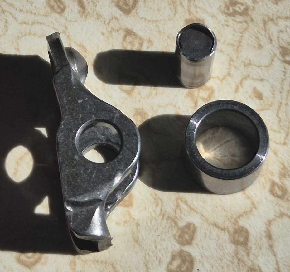
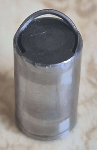
I broke it again.... I was giving it some revs again and running through the gears. Got up to around 8600rpm. Loud ticking noise getting louder, pulled covers off to investigate. Found that one of the rockers had dislodged, but, not really dislodged. The bearing has come out of the center. then after that the rocker likely flew off, and then a valve got bent in the process somehow. So, not hugely bad in terms of engine damage... The biggest expense is time spent replacing the valve. I think the motor I pulled apart from last time at pickapart to get the intake valves out of. Is still there waiting for me to go grab some exhaust valves haha. Although it'll be tricky to get this bent valve out, as it's bent from the top. Might need to cut it off somehow. With regards to a long term fix. Seems there are two possibilities and I'm not sure which yet. Either the pin vibrated itself into the 5th dimension, and just pushed itself all of the way through the rocker one side to the other. Or, the rocker flexed enough that the pin and bearing could come out the top. So will investigate some options to beef them up, but might be time for a CNC project for some beefier rockers. Someone mentioned to me that Papidakis racing was running a 9000rpm 2AR engine, and they have the exact same rocker setup in the head. I watched a teardown video, and turns out they ended up making some beefed up rockers to alleviate a few issues. So that might be best way to go. Also, although it's annoying to have another breakage, reminder to myself that this is what I signed up for. There are plenty of well trodden paths to go down, this is how it goes when there arent 5000 other people who've done the same yet. Engine knowledge is written in blood! Will be interesting to see if there are any signs of deformation on any of the other rockers, they all looked alright by eyeball so far. EDIT: Okay I know a bit better what happened now. So the pins arent even press fit, they are just staked in place. So I can actually slide the pin all of the way back in, very easily if you get it right way around. there is juts a C shaped stake on each side, holding it in. So on this rocker the staking lifted, then the pin could easily slide out. So the pin definitely came all of the way out one side, not flexing the rocker and out the top. So a tiny tig blob on each end might solve it, if I can weld accurately enough. haha EDIT 2: I asked around on a Facebook group for 2GRs, if anyone had had similar issues. Someone mentioned that this is a common problem with the Boxer motors in the GT86, and so the they tig weld the ends, then it's never a problem again. So will proceed as planned!
- 131 replies
-
- 38
-
-
-