Roman
-
Posts
7,218 -
Joined
-
Last visited
-
Days Won
39
Everything posted by Roman
-
@Hyperblade yeah inconel was more like $1200 each and then well and truly out of my depth to try weld it. But I doubt i could even make a stainless collector like that for that price.
-
Good news is that the head looks okay, valve guides look okay, exhaust valves look untouched. Just intake valves got pretty tweaked! There's a few tiny marks on the pistons but nothing to worry about. Because I have stiff valve springs, and the valves were held about half way down because of the bends. It was an interesting experience banging the collets out. I may have fired a few into orbit. So need to get some of those when I go to pickapart to get new valves etc. I was also cursing at the fact that I need to take the sump off, in order to get the front cover off to reset the timing. If I need to take the upper sump pan off, it's an engine out job which I dont really have any space to do. I managed to get the cover mostly off by only removing the lower bowl, and undoing the cover bolts from underneath - but then it seemed stuck so I resigned to the fact that I'd have to take the sump fully off. Then I remembered that the oil pickup tube is attached to the oil pump, which is on the front cover - Which was what was jamming it. Ha. So when I undo that, hopefully the cover comes off no problem. In other news, I saw a video from Papadakis racing where they fully made a turbo manifold from 3d printed inconel. It looked absolutely friggen amazing. So I thought for interests sake, I wonder if there's anywhere that 3d prints metal that could give me a price online by just uploading an STL file. So I drew a collector with no particular science to it, just to get a shape to get a ballpark figure. Expecting zillions. Much to my surprise, one of the places could do it for $250NZD from 316L stainless. Which seems absolutely incredible! The prices for getting aluminium printed seemed completely sane as well. For some smaller or more complex objects, this might be a no brainer. So at some point I think I will get one made and see how it looks. Then order a 2nd one for the other side if it's any good. But I'll do some more investigation on what makes a good collector shape first. This will be by far the cheapest and easiest option, and potentially the best shape too. I'm excited about it. It will be cool to be able to make some organic shapes without being constrained by working just with a constant pipe diameter. Might be a month or three down the track though. But thats what I'm fizzing over a the moment.
- 130 replies
-
- 43
-

-

-
FS: Ulta high flow valves, Using stem curvature technology to maximize intake airflow. 4x more airflow that a regular valve, due to letting air in on every stroke! $400 ONO, no low balls. I know what I've got Should have the head off by tomorrow some time if the weather stays good. Looks like the other bank is totally fine, hopefully the valve seats and so on are okay on this one. Juts whack some new valves and cam pulleys in hopefully. But thats best case scenario EDIT:

- 130 replies
-
- 42
-
-
-

-

-
Sounds like I dont need to try at all, just keep making them no matter what EDIT: Looks like there is a 2009 onwards model Mark X at PIckapart Mangere. $25 each for pulleys so might go grab all four if they arent looking too manky. Otherwise it's around $300-400 each for brand new items.
-
Just asked some 2GR guys, they said they have seen the bolts back themselves out on 2009 or earlier motors, if the locking pin wasnt engaging. As it slaps around like crazy before oil pressure can build. So way stiffer valve springs and yep. Sounds like there have been a few iterations of pulleys, so might just suck it up and buy some new ones. So not completely my fault this time by the looks...
-
Bought from Dodsons, assumed running engine. I doubt its any historical issue that caused it. Maybe just lots of cranking with low oil pressure, so the pulley slaps around like crazy if the chambers havent filled with oil... But that would only be an issue if the locking pin wasnt working, which is a common issue on these apparently. So will give them all a good check. Then price up some new pulleys if needed. I dont mind blowing this motor up, but i was more hoping for a blaze of glory spreading its guts down the 2nd half of meremere
-
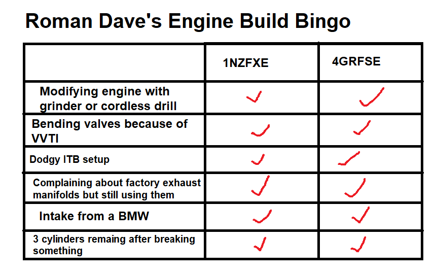
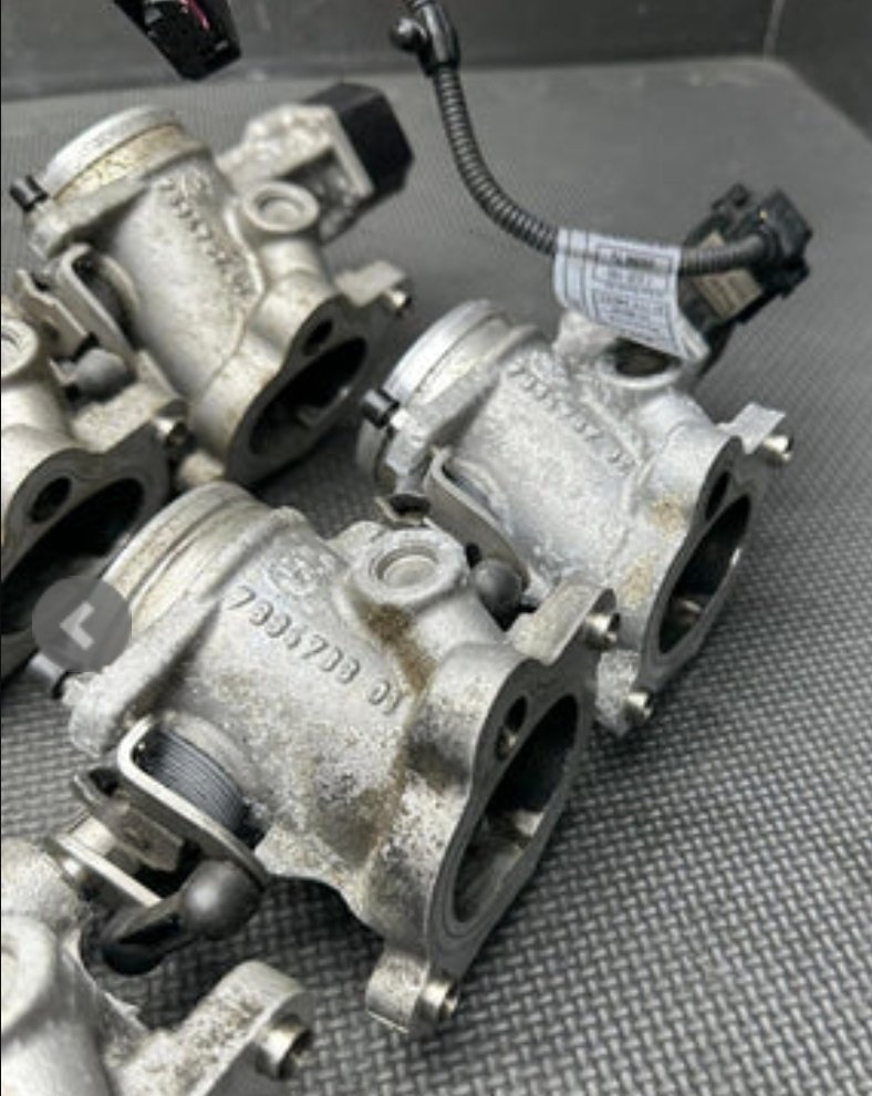
For god knows what reason, the VVTI pulley on the cam that spat the rockers had lost its bolts. Whether this is cause or effect, I am unsure. But im now concerned that maybe the valves conked into pistons or something, then all of this stuff is just a consequence of that. So I need to do a bunch of checks. I definitely hadnt touched these bolts, as they are a weird 5 sided internal hex that I dont even have a tool for. Weird! So this has now officially escalated into a full blown fuck-around. As the bolts have gone part way down the timing cover. Also one of the valve caps has made its way to the sump by the looks. So no shortcut options, its all going to have to come apart. As I cant get the timing cover off, without the sump off. I might get lucky and its just the lower oil pan that needs to come off. Not stressed about it, but just more annoying stuff to sort out. I cannot overstate the peace of mind that comes with using a cheap and replacable engine. I think id be at stress level 5000 if this was anything more expensive or uncommon. But no stress. EDIT: Some of the 2GR guys that I asked, said they've seen this a few times before. Happens on the pre 2009 engines. Apparently Toyota went through a few revisions of their VVT pulleys, and later ones were better. The root cause is indeed when the locking pin stops working, that is supposed to hold the cam in place until there is sufficient oil pressure. The internal parts slap around very violently when there's no oil inside on cold starts. This would have been exacerbated by the very stiff valve springs that I have fitted. So this wouldnt have happened if the motor was just slapped in a car and run standard. However, it's also a known issue that I'm not sure I could have anticipated so I feel a bit better about it.
- 130 replies
-
- 32
-
-
-
-

-
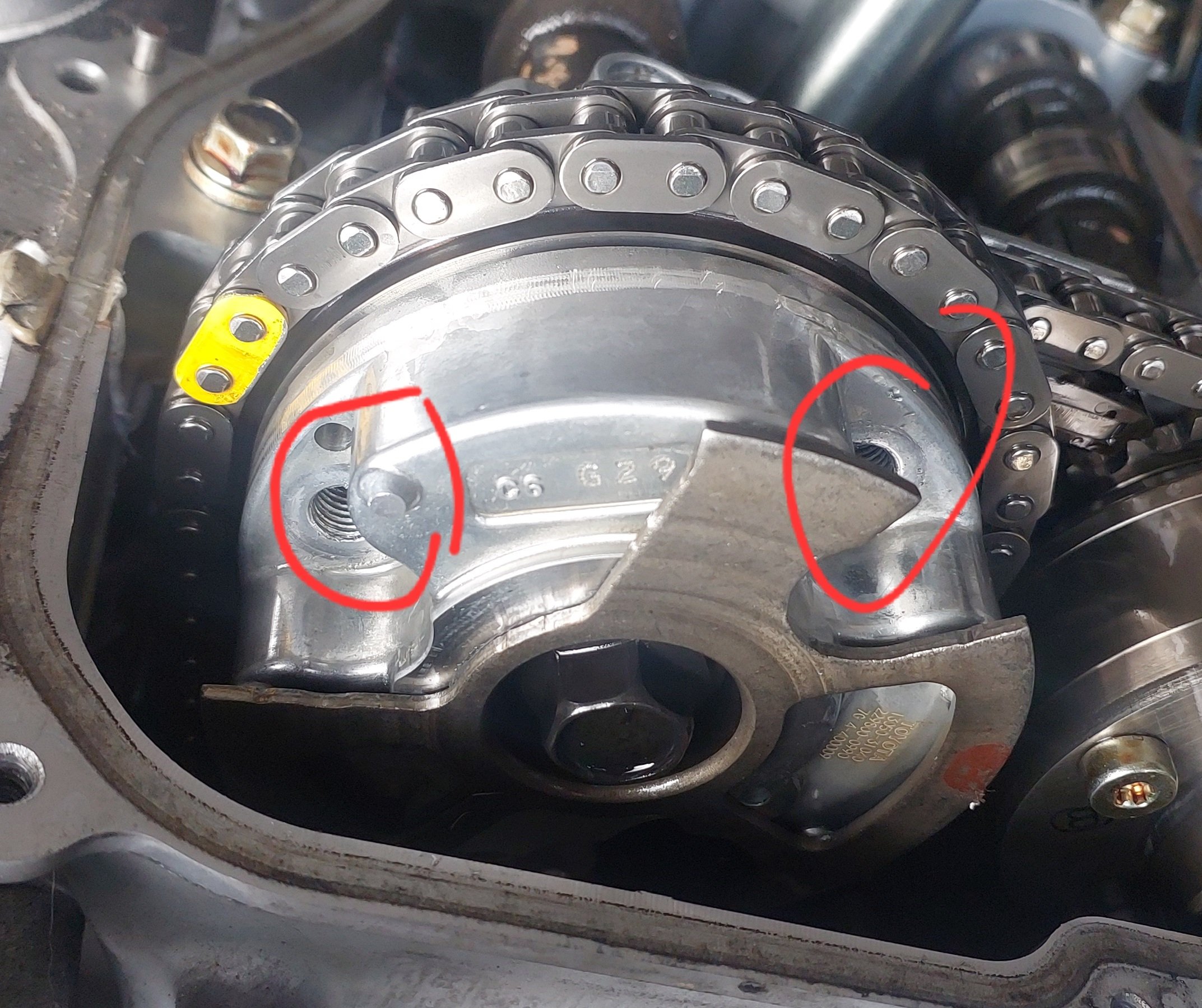
It turns out the crank sensor polarity was indeed the right way around, but, maybe the shielding could have been better? So I remade the wiring, and rerouted it away from the alternator. Still flames out the intake... hmmm. Everything was looking good on the trigger scope so it didnt make sense. So maybe time to start checking for mechanical issues. I run a compression test, one bank is getting between 130-150psi... However the other bank was zero zero zero. first thought was that I must have bent some valves, or the valves arent seating correctly and need lapping in or something. I pulled the rocker covers off, and found that all of the rockers underneath the intake cam on that side had fallen off... Not 100% sure why yet. It may relate to me doing a half arsed version of bleeding the lifters before installing them. As I only found out the proper way after I'd put it together. You need to stick a needle down the hole until air stops coming out, while the lifter is soaked in oil. So maybe it was the combination of starting a motor with no oil in the VVT pulleys, no oil in the lifters, and then the extra heavy valve springs making things whip around more than usual, and flicked things out. Not what I was expecting. I will triple check the cam timing next. If that's good, I'll see if I can manage to pop the lifters back in without removing too much stuff. One thing that sucks about this motor is that the front timing cover can only come off, by undoing some bolts that are inside the sump. So hopefully that's not needed, but see how I go. In terms of removing everything to get the covers off, the motor passes the serviceability test for the most part. The only annoying thing was having to disconnect the clutch MC in order to have enough room to get that side's cover off. I think once I've got a rear firewall in though, some tasks will be a bit harder.
- 130 replies
-
- 31
-
-
Definitely experiencing a combination of wins and losses with things right now. I fixed the wiring on my cam angle sensors, and then it actually looked fairly easy to change the wiring to an 8v supply so I did that too. ...Then the motor wouldnt start at all. It looks like it would work well with an 8v supply, if you use pulldown resistors instead of pull up. So pulled the loom back out, changed it back to 5V supply. Once I got this fixed, the motor would fire up again. Sort of. I guess "fire up" is probably an accurate description: What the hell is going on? How can the timing be obviously so bad, but the motor still runs at all haha. Well it looks like the polarity of the crank angle sensor is back to front. So every now and then it thinks its doing a zillion RPM and then ignites on the intake stroke. So some fairly rookie mistakes going on. But I'm slowly sorting through them. I think it should be idling and running properly pretty soon, hopefully. I've not had any time to fit the exhausts on properly so my 1 stroke external combustion engine / fireworks machine is still pretty bloody noisy.
- 130 replies
-
- 35
-
-
-
Yeah ultimately what you are trying to measure is rate of acceleration. Since the mass of the vehicle is fixed, being able to accellerate this at a given rate is a fairly good indicator of your power level. Do you have any logging capabilities with your ECU? Virtual Dyno really is amazing, but you have to constrain all of the variables really well. One problem that even virtual dyno has, and it's way less sensitive to this than a strain gauge - Is that any bumps in the road need a heavy degree of filtering. If you were monitoring load on a driveshaft or suspension part or whatever, you're going to have an incredibly poor signal to noise ratio. If you've got a few bucks to spend, have a look at Dragy. I've seen some friends run these at the drags and have some results back that are insanely close to their actual quarter mile times. https://dragymotorsports.com.au/ The main thing about road testing though is you have to try constrain every variable possible, as much as possible. Not so necessary on a dyno when the car just sits there, more or less.
-
I ended up pulling the whole loom out to check things on the bench. It took a few hours to figure things out, I had made a few mistakes. Since I have pullup resistors on all of the cam angle sensors, the 5v supply on that loom plug splits 4 ways and joins to the signals. However I'd swapped the 5v supply wire with one of the 5v/DI signals on one half of the plug. So looking with a multimeter it still showed the correct amount of resistance on that DI, but, it was the wrong way around. Then I also found a broken wire at the plug end of one of the other DIs. Then I also found one of the pins in one of the plug halves was pushing back out when you put the plug together. So replaced the plug. I've got all of them responding on/off when holding steel against the sensors. While I was there I also changed the supply to 8v instead, hopefully less chance of trigger errors. Hopefully it'll all work okay now.
-
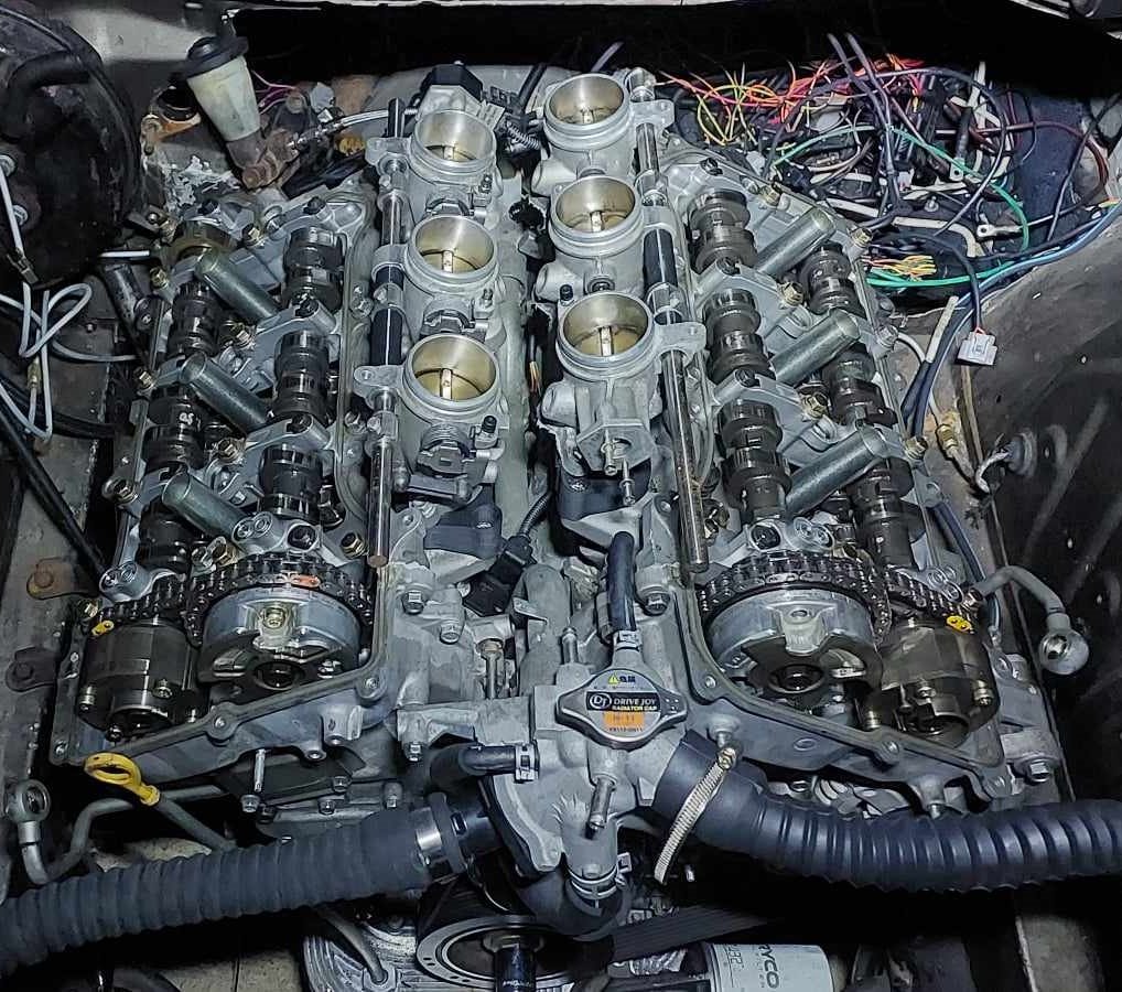
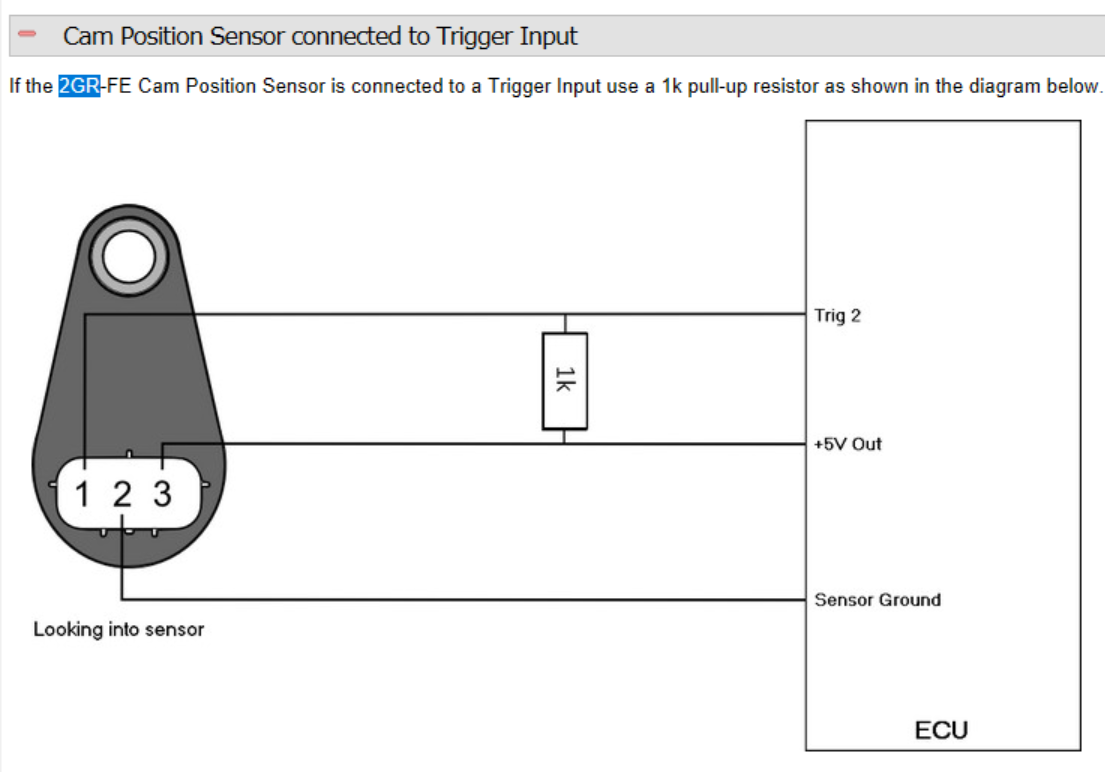
Yeah so the trigger code for the 2gr lets it run as wasted spark / batch fire until it gets a cam trigger signal. So originally i had timing 360 deg out, then it would work as wasted spark but then cut out when it found trigger 2. Ha. Yeah so there are 4x cam angle sensors for vvti, one gets connected as trigger 2 then the other 3 to DIs. According to some old posts on the link forum the trigger decoding only works if set to falling edge. As otherwise the timing of crank vs cam overlaps in a weird way for vvti range. Will do some checks with a multimeter tomorrow.
-
Yeah, pullup according to documentation.
-
Ive been making good progress on getting everything wired into the fusebox and controlled by ECU rather than hardwired. I bought 2x 500mm coby hotdog mufflers which are currently just sitting pushed over the ends of the pipes on each bank. Quieter than just open manifolds but should be better once welded. Have wired up ECT, wideband, fuel pressure sensor. The motor was still idling really high (like 4200rpm...) with fully closed throttles, even after setting everything to fully closed. I couldnt figure out why until I noticed that my 2x lower intake manifolds dont quite cover the edge of the circular holes which must be an idle air bypass. It was only by a smidge, so gooed the gap with some silicone and solved that problem. My current issue is that the cam angle triggers arent being picked up properly. This motor uses hall effect sensors on the cam angle sensors, and the voltage they output is too low for this ECU to register correctly. So pullup resistors are needed, which I have wired in. But stilk not working it seems. Some people have suggested wiring them to the 8v power supply rather than 5v supply, and this boosts the output voltage. But this stuffs up my loom a bit, as the 5v supply on that plug branches to a few other things as well as the triggers. So, another annoying problem, but not insurmountable. Just soaking up more time on little bits and pieces than expected. But thats always the way I guess!
- 130 replies
-
- 29
-
-
Ahh ive always wondered what the point of those drag specific front tyres was. (For rwd)
-
Agreed, looks so good! Love this car. Going to come to the night speed final next Friday?
-
Went to pickapart and replaced the missing air bleed hoses. Fixed a few other coolant leaks. Now it's good. Bought a big syringe pump thing to fill the gearbox with oil, managed to do this notoriously messy job without spilling a single drop of gearbox oil! Miracle! Until I realized that the drain plug wasnt screwed in properly, and itwas on an angle - so I had to undo it and quickly straighten it and tighten it up. So gearbox oil everywhere still. Damnit, haha. Then I think I've still got some fairly massive air leaks, I dont have any gaskets or sealants at the moment so I'll pull it all apart and sort that a bit better. I managed to get it idling at around 1000rpm, but only because I've leaned out the fuel table so much. Again an easy fix, just time consuming. Then another cool milestone, and to be honest something I was dreading a bit - testing the clutch. Everything's good! I drove the car forward about a meter, then reverse about a meter. Which is officially the furthest it's propelled itself in about 6 or 7 years. It's still ear splittingly loud, and dear god it sounds like a straight piped RB or something dreadful currently. Ugh. Will buy some mufflers this week if I can, so I can keep making some progress without making my brain bleed. Then also have enough of an exhaust on there that I'll be getting okay readings on the wideband. Small steps but all in the right direction currently. nother
- 130 replies
-
- 33
-
-
-
Yeah will probably merge into a single 3" pipe to back of the car. Probably better to go even bigger, or have separate pipes for each bank all the way to back of the car. But it sounds better if you merge them. Also it gets a lot harder trying to have some decent mufflers under the car once the pipes start getting bigger.
-
Nah, I think I punished him enough with non 4AGE related work already. Apparently he stays up late at night washing his hands, still trying to get the stink of 1NZ off them... For now it'll just be the factory manifolds and then try do the rest of the exhaust nicely-ish to suit end goals. Then flanges to suit putting some nicer manifolds on as things progress.
-
Yeah I bought a delorian in another 10 years time. Ive had it for ages
-
It's taken longer than I hoped to get to this point, but damn it sure felt good to hear it fire up. Even though all it can do at the moment is idle (poorly) at 2000+ rpm haha.
-
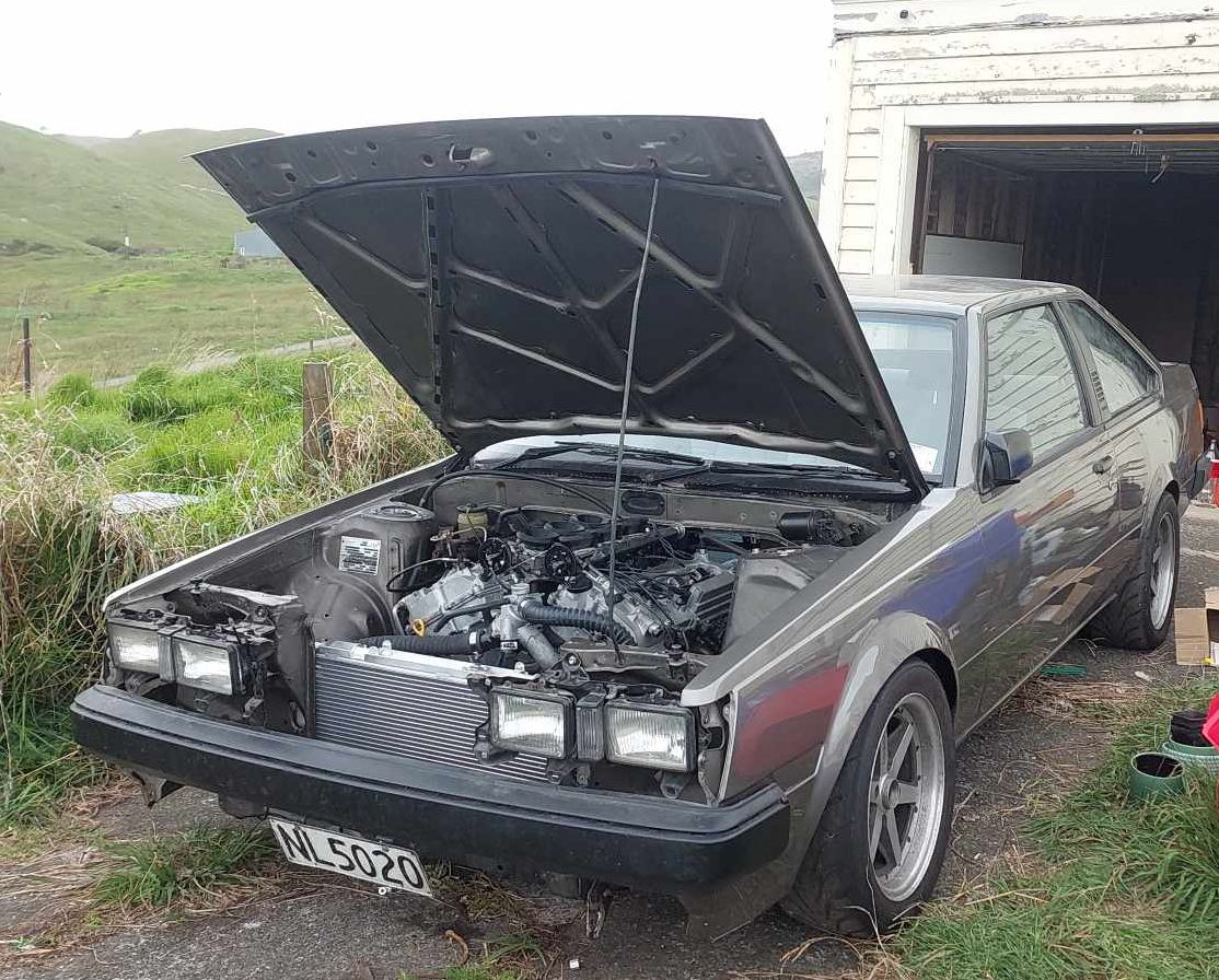
Alright alright alright! So I pushed the car outside this afternoon so I could reach some wiring inside to try fire it up. I filled the car up with coolant, by which I mean water because I was expecting things to leak. Sure enough each head had a hole up the front where water started leaking out. I couldnt remember what these were for, then found out that they are like an air bleed channel that goes back to the thermostat housing. So, these seem to have gone AWOL when moving house so I'll need to pickapart some more. I must have removed them when taking the heads off to clean them. Easy fix. Then I got the fuel pump working and fixed a few fuel leaks. It turns out that AN fittings arent very good at sealing if you havent tightened them up? Crazy. Then I got my tune somewhat sorted, and tried cranking the motor over.... and the bloody battery died! Ugh. I mucked around to get another battery, it sort of spluttered a few times but not quite. I had a look through the tune settings. Engine size was still set to 1500cc from using this ECU in the Echo - woops. I needed to disable the fuel pressure sensor allocation. As since this isnt wired in yet, it took 0v to believe that the motor had zillions of psi worth of fuel pressure. Then when I cranked the motor it was registering the crank trigger, but not cam trigger. Checked the settings, had this wrong. Both were set to VR sensors, but the crank is VR and the cams are hall effect. So once that was fixed... Bam! We are running. It was absolutely awesome to reach this point. So whats next? Lots. Get the coolant system functioning properly. Make an exhaust for it. A lot of wiring work, get the fusebox setup all connected nicely and mount all of the wiring nicely. Need to put some gearbox oil in the box, will do this before running the engine any longer. Pull the fuel rails off, and do tests to work out the CC rating and deadtimes for the injectors. Calibrate all of the sensors Mount a radiator fan Check intake for leaks (I think all of the air bypass screws are currently all the way out) Install the wideband Finish wiring up the alternator And a bunch of other little similar jobs. Most of these I can peck away at over winter with limited space. Making an exhaust will be difficult when weather starts getting darker and wetter and I can only really work outside. Will push ahead as best I can. Super excited for first start though!
- 130 replies
-
- 68
-
-
-
If you can only find one with right geometry but too small a bore, you can get them bored out and put bigger guts in Bit more of a pain than finding an off the shelf option though.
-

Mitchs is never going to finish 2zz Ke70 race car build discussion
Roman replied to Mitch.W's topic in Project Discussion
Sidetrack to your build and sorry/not sorry. But the biggest tragedy with the 2ZZ was that they made the 1ZZ and 2ZZ completely different engines. They were trying to make a competitor to the B18C but totally missed the point in that regard. Like how good is the B18C, on account of that even the peasant versions can be awesome, with just different cams and so on. Can you imagine if every single turd car out there with a 1ZZ, had 2ZZ potential? Would be incredible! But instead we have zillions of 1ZZ turds and very few of the cool motors around. -
When I took my 1NZ with cams etc for a WOF with the standard intake manifold on. You could not have believed it was the same engine. Holy crap, it turned into a slug haha. Totally choked out by ~5000ish rpm. If the 2ZR was similarly designed, it would be a night and day difference with some bolt on mods. However yes - I must concede that some motors like 1NZ and 2ZR do in fact totally suck in factory form.