Roman
-
Posts
7,224 -
Joined
-
Last visited
-
Days Won
39
Everything posted by Roman
-
@GARDRB Fuel pump control is simple, you just assign an output to turn on when rpm is over 100 (or whatever) Assuming there isnt a specific function for it which does that.
-
G4 cant upgrade to a G4+ or anything like that. I'd recommend downloading PClink for both G4 and G4+ and see how they compare. G4 software is alright but a bit more janky than G4+ which has had another 10 years of updates or whatever. If you've got a serious itch for ethrottle, that's the only reason I'd consider the G4 xtreme over a G4+ storm. (assuming G4 xtreme does ethrottle, cant remember)
-
You should, I bet you've got a lot of power hiding in your ignition table at the moment.
-
Woops, didnt notice the plug on that one. I use the ones that use an EV1 (injector) plug https://vi.aliexpress.com/item/1005006120877474.html
-
If it's MAP based, then IAT decently contributes to the airmass calculation. But if it's MAF based then IAT does hardly anything. Maybe you could wire in a potentiometer, so you can adjust it and see if you make any gains. haha
-
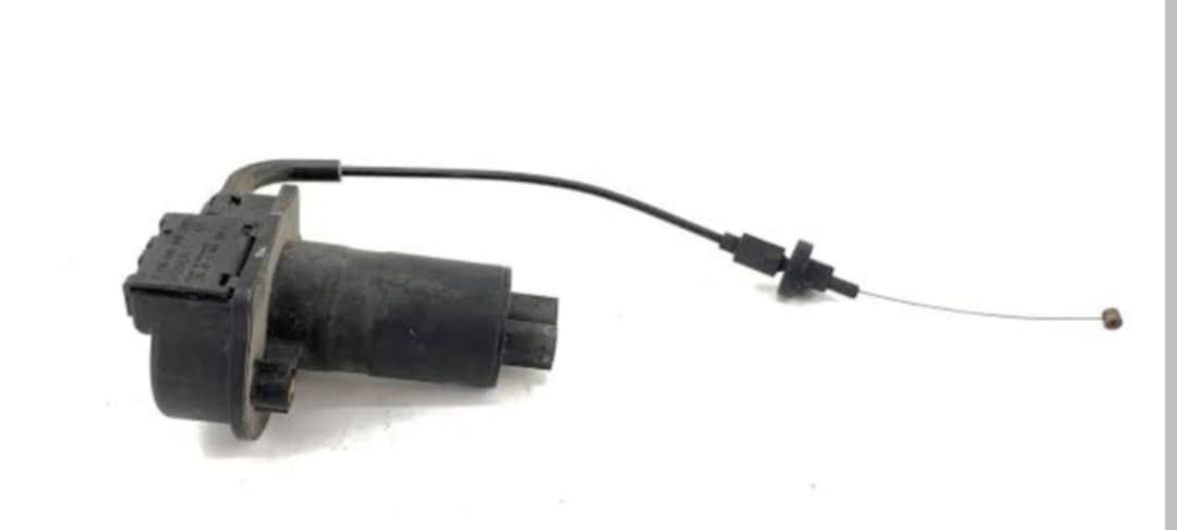
If you get canbus based wideband controllers, you can run one in each bank and read from them both. Then this way you also dont use up any of your precious analog inputs, annnndddd its way more accurate. G4+ is pretty good but honestly wouldn't recommend going older than that. As the software is a bit more janky and you'll grow into some of the features that are in G4+ but not earlier models. Idle speed correction isnt a huge deal really, but yeah get rid of the stepper based one. You can calibrate any sort of IAT to work, same goes for MAP etc. However I've got a favorite that has good fast response and they cost nearly nothing. Dont go paying $100 for an IAT sensor, they are literally just a 0.005c thermistor with some plastic bits to hold it in the air stream.
-
Here's another thought. You have a high pressure zone right at the nose of the car. then a low pressure zone right at the middle of the rear of the car. Why not run a big tube through the middle of the car, that joins the engine bay firewall to the lowest pressure area at back of the car. Turn your car into a donut for reduced cross sectional area. Haha
-
I guess another way to look at it - There are fast as fuck race cars, that do any and all of the above. So long as you are following some well established general principals I'd not get too hung up on the details for starters. I bet there's a fairly decent deadzone where you get similar results from lots of different ways of doing something. Where different wings or angles etc are a fairly linear drag vs downforce tradeoff. Then you're chasing incredibly diminishing gains to optimize it all. Might be time for some sideskirts? 🤐
-
Or if you can find an ecu for cheap, and an obd2 reader. If you keep the MAF in the standard sized pipe the ecu's MAF scaling will tell you grams/sec airflow.
-
The Alfa 155 DTM cars did the dual radiator thing where they come out in front of the wheels. But yeah I agree its likely more to do with rules than ideal aero. I am guessing much like BTCC, they werent allowed to change the body panels much or at all. So werent allowed to chop a big hole in the bonnet, but modding the bumper was fine. So it was probably just best way to deal with a bad situation handed to them by the rule book. It's funny how many times race car stuff isnt "ideal" so much as, just best conforming to some really abstract constraints.
-
I just used Ali ones and they have been fine so far. But I cant give commentary on if they stand the test of time or whatever. However the crimp terminals have all been nice.
-
I quite like the Sumitomo plugs, just google "Sumitomo 12 way connector" or whatever and heaps of things come up. Have used these to make sub looms on mine.
-
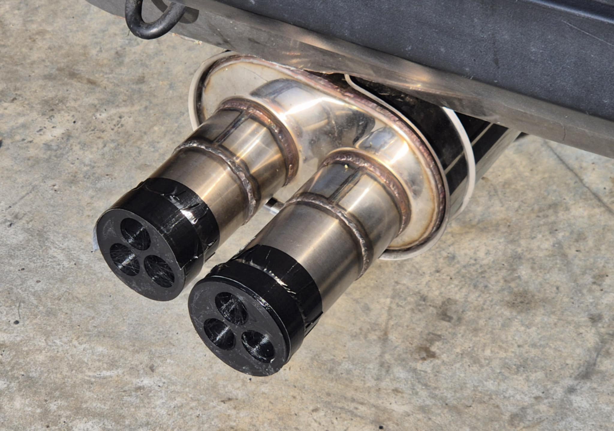
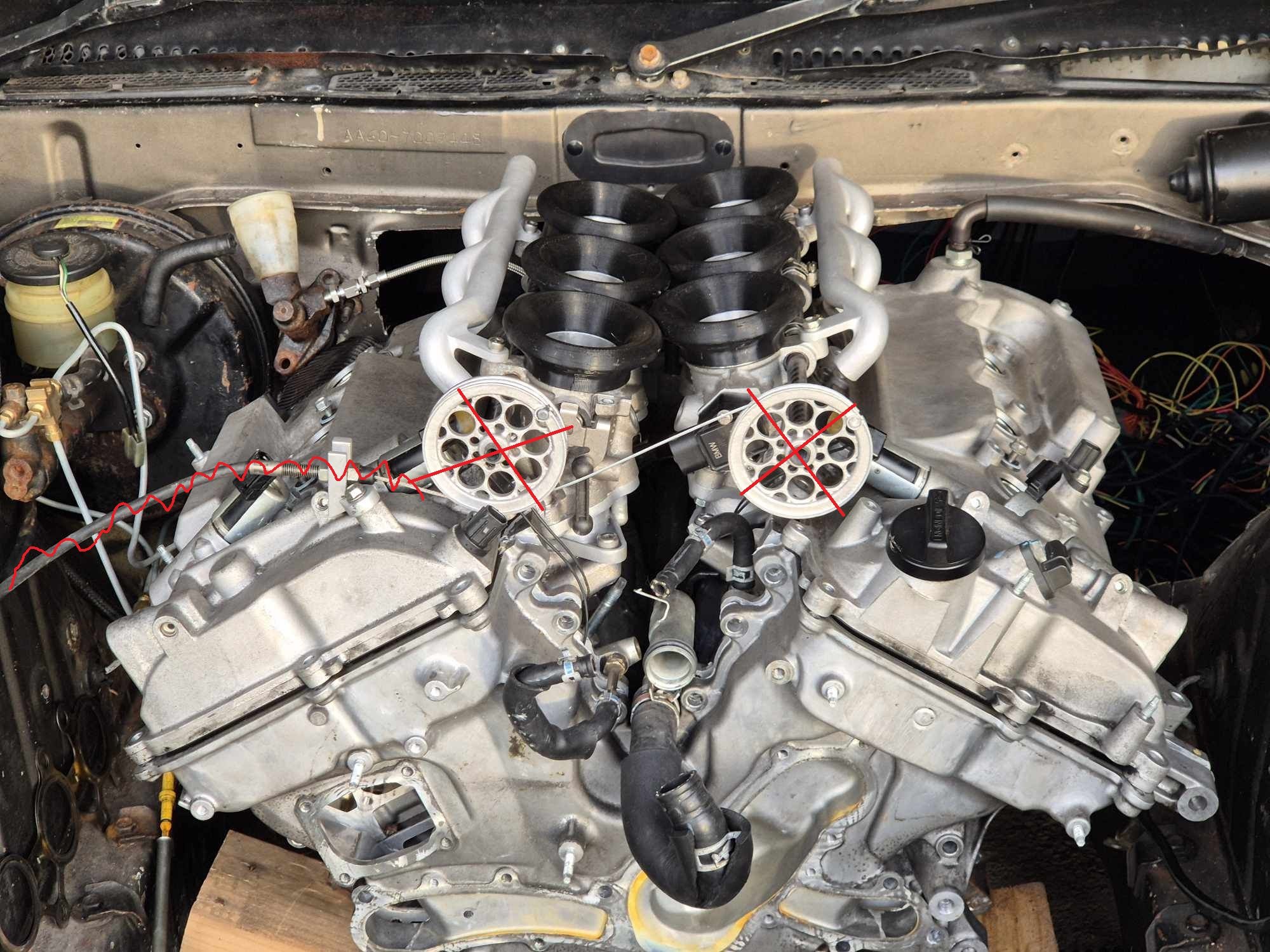
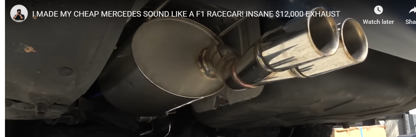
I havent had a chance to do much exhaust testing, apart from trying some gatling gun looking ends. So this still has same cross sectional area as a single 3" pipe but it has longer pipe bits which protrude in, and has bellmouths on the entrances so it's hopefully not too restrictive. Surprisingly, it does in fact sound a bit better even at idle. God bless PLA and duct tape. Changing the tips is not getting the sound I need/want (Didnt think it would be that simple, but best to rule out the easiest possibilities first) I cant show some nerdy stuff about wavelengths etc because it was incredibly windy at the time. Some ethrottle junk turned up in the post. I gave it a test and it works great! A single motor could pull open both banks, no problem. So having 1 motor per bank and it should be super snappy. I've got an ethrottle pedal from a Toyota Aqua wired in, and have the ECU running one bank through the onboard ethrottle. For the second bank my dashboard now doubles as an ethrottle controller, and runs an H bridge to power the 2nd motor. So a high priority CAN message gets sent at 200hz containing ethrottle target (throttle %) and actual throttle %. Then it applies a PID routine to output a frequency to the H bridge to give it some juice. It's all wired up and just needs PID settings locked in with some testing once it's operational. Since I currently need to run ethrottle from the same microcontroller that does dash stuff. I need to make sure I'm not hogging the processor for half a second (or whatever) with screen updates or something. Currently my code has just been running in a loop, updating the screen every time it can after receiving some CAN data. I never checked how quick this is, but its zillions fast. I've now cut it down to a fixed refresh rate of 50hz for screen refresh, 200hz for ethrottle PID routine. Then the rest of the time it just sits there collecting CAN frames. It's managing to catch 20+ lots of can frames in between each PID routine so there shouldnt be any issue getting the relevant ethrottle data from the ECU in time. I've added some other bits and pieces to the code to make it easier to draw features, change color scheme and so on. It's still not quite the aesthetic I want but it will do for now. I've ordered a Teensy 4.1 (rather than my 4.0) as this has an onboard SD car slot. Meaning I can load gifs and bitmaps onto the SD card so it can display them on the screen. Once that turns up I'll have the 4.0 as a dedicated ethrottle unit, and 4.1 just for the dash. I've drawn up some new pulleys that can sit underneath the fuel rails without bonking into anything. New one looks like this. No holes or anything, as I dont want to have any chance of snagging on something or jamming while it's further down in the guts of the intake setup. So all of this stuff can go up on the wall of shame, and make way for an airbox. Alsoooooo some Kelford cams turned up! Exciting. Big cams are the make or break for this project, so it's exciting to finally have them. Am I completely full of shit about this motor revving out good? Lets see. Haha. Lots to do at the moment but very busy. The plan from here is to finish the ethrottle setup. Then get a decent full throttle fuel map / VVTI map sorted on the factory cams. So I've got a good baseline for comparison. Its incredibly annoying how much of the motor you need to take apart to swap cams. If it was easier, I'd probably just do it straight away. Haha.

- 131 replies
-
- 30
-

-

Hyperblade's KP61 Racecar "KP61R" Discussion
Roman replied to Hyperblade's topic in Project Discussion
Haha wow, thats some uncanny synchronization! -
I ended up moving house and not having any garage space any more. There is an fb group for diy flow benches though, and using a MAF is a popular option. Might get back to this one day, but not any time soon
-
Yeah the reason thats needed is because the FXE pistons have shallower cut outs, which is part of how they get the higher CR. Hopefully the factory valve pockets on the 4GR are alright to get the cams setup on the factory timing marks.
-
Might not be any point with my motor. Since it's got a longer rod ratio than the 2GR, the piston dwells at TDC for longer. So it would likely hit pistons sooner than a 2GR. Maybe cant make use of the extra range anyway. Will see. Ordered big cams! Exciting
-
The 2GR is normally 10:1 compression or something, and the FXE pistons bump it up to 12.5:1 The 4GR is 12:1 by default, and there's no FXE version. As the 4GR is already a race ready engine (conditions apply) Conditions: Absolutely garbage valvetrain, pulleys, rockers, valve springs etc
-
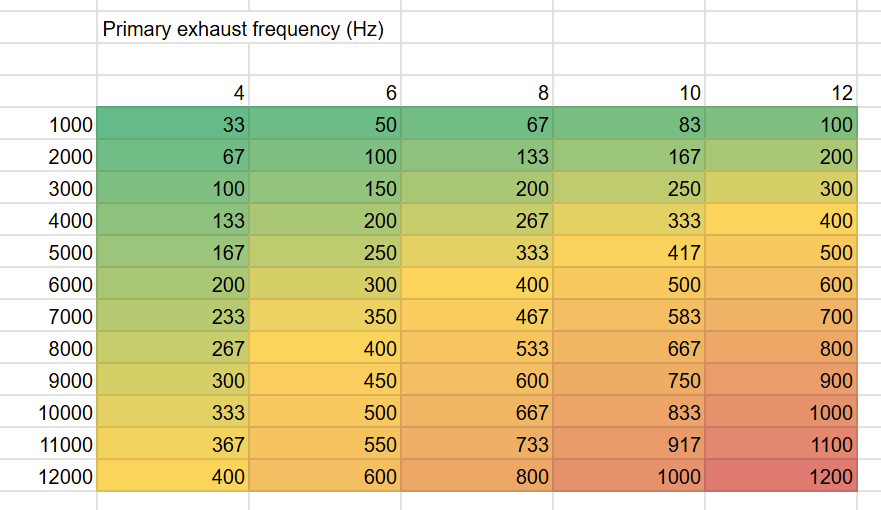
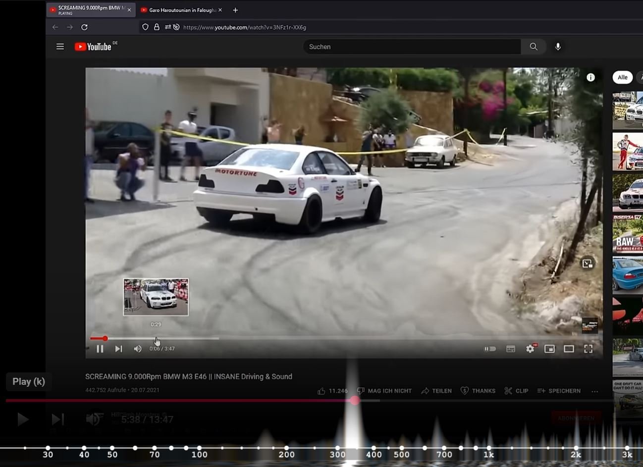
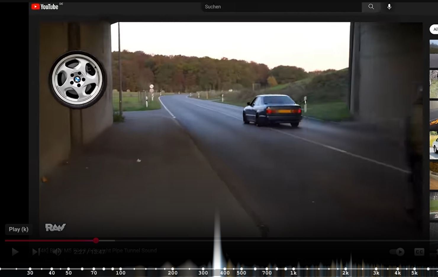
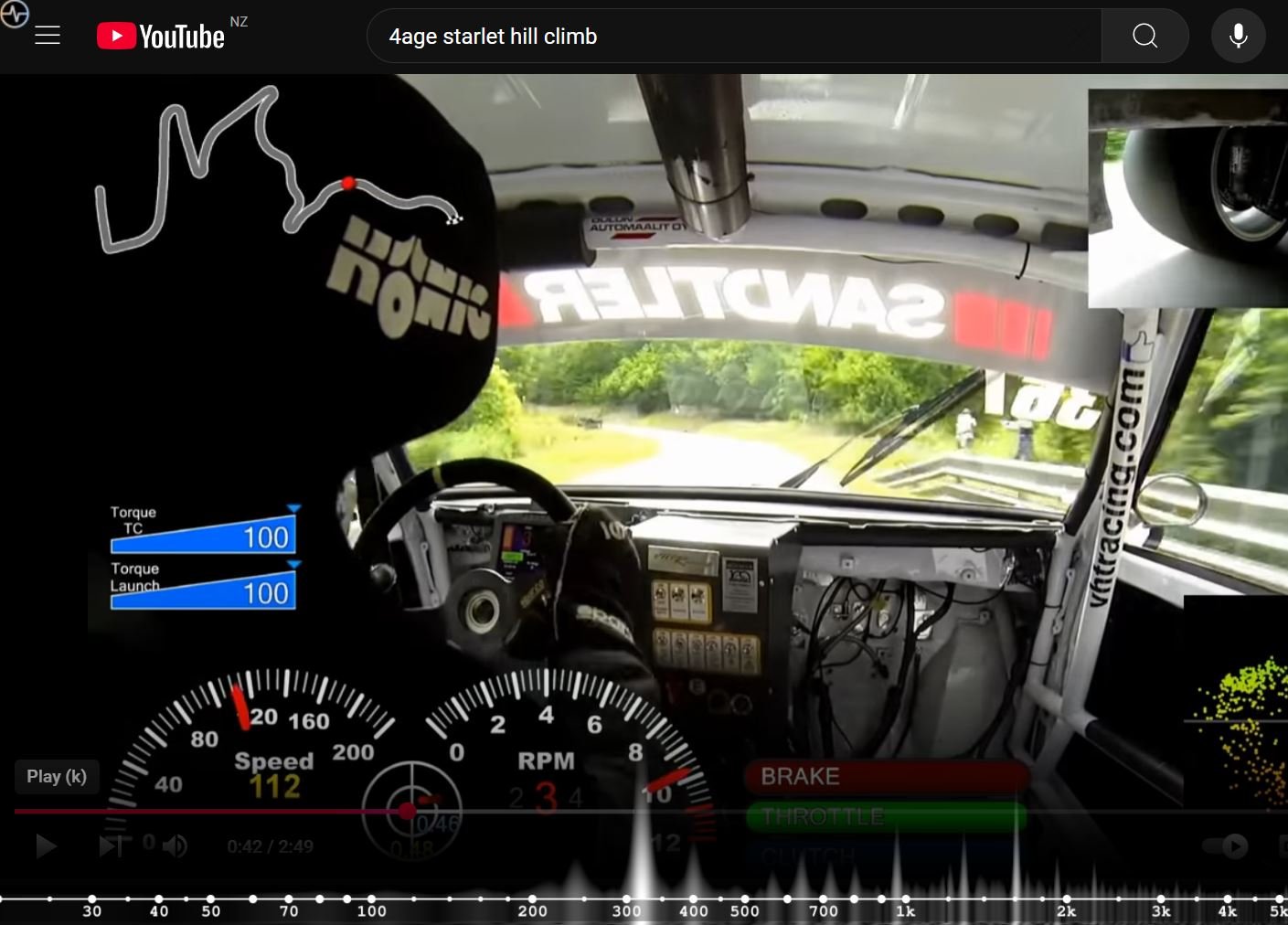
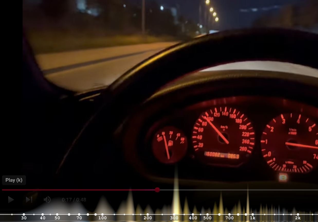
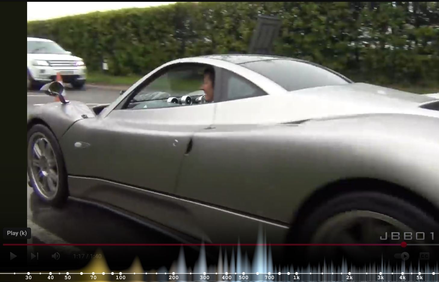
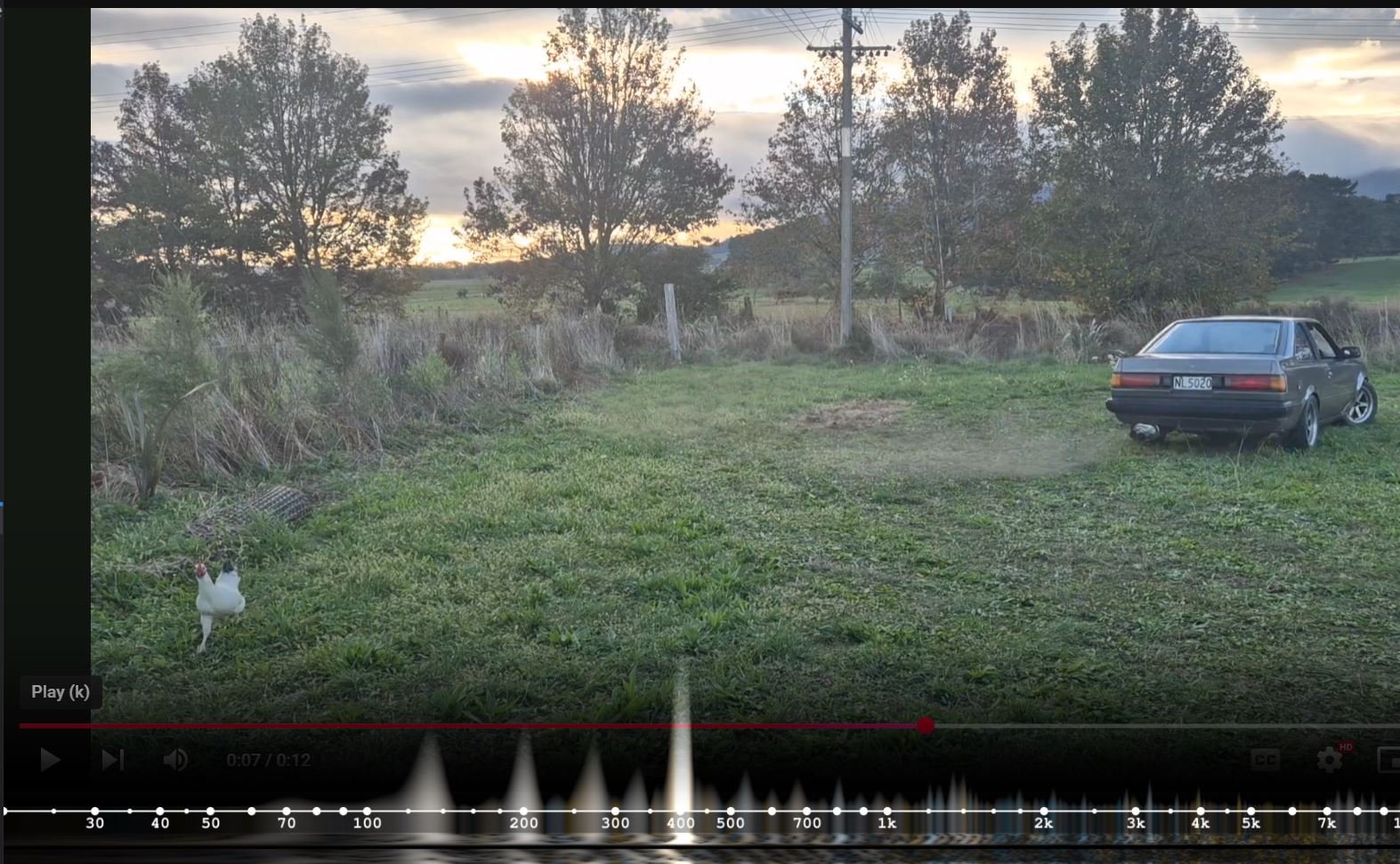
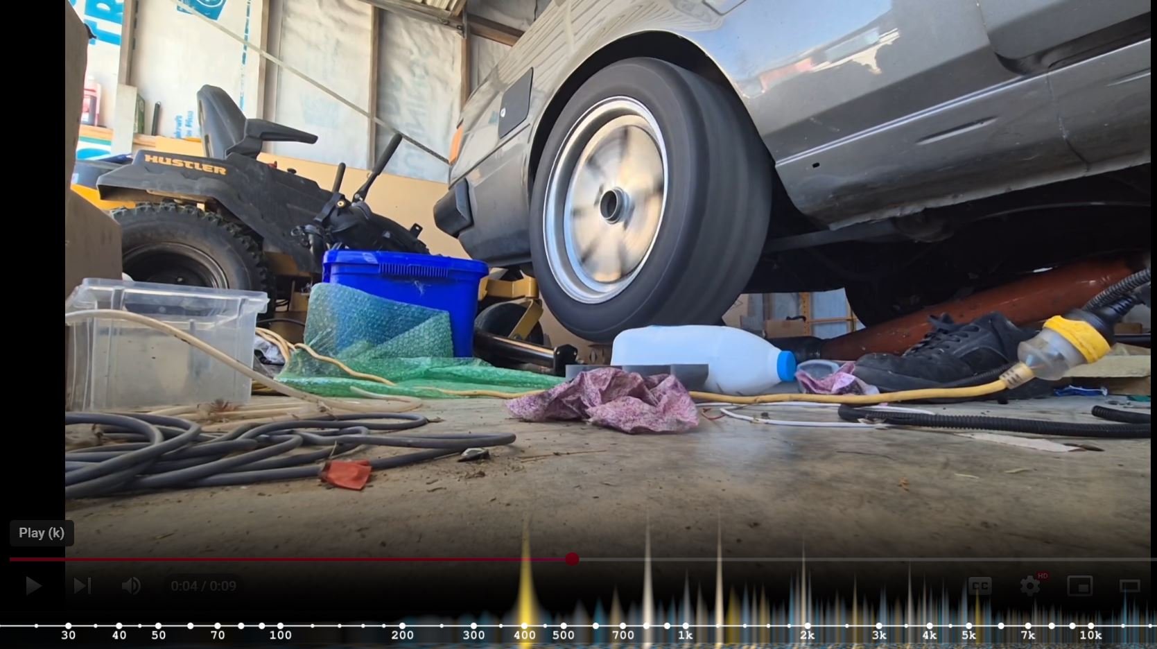
Exhaust noise stuff Alright alright alright. So, for this motor I've always envisioned it having a more high pitched racey sorta sound. Kinda like a motorbike with more cyls. What I've got at the moment is like a gluggy V8 sort of sound coming out, even when it's revving out nicely. So in order to fix this I think I need to somehow quantify what "good noise" and "bad noise" actually is. So any engine has a fundamental exhaust frequency that relates to the number of pulses coming out of the exhaust. So for example. A 4 cyl engine doing 8000rpm. What is the frequency of the exhaust pulses coming out of the engine. 8000rpm x 4 cyls divided by 2 because each cyl only fires once per 720 deg. Then divide by 60 to convert from rpm to hz. 8000 x 4 /2 /60 = 266hz Then another example, a V12 engine doing 6000rpm. 6000 x 12 / 2 / 60 = 600hz So obviously a V12 is going to sound higher pitched, as it's got more events going on. So that's one thing that you cant change about the motor. With some excel nerding we can figure out what sort of freq a 4, 6, 8, 10, 12 cyl motor naturally makes at a variety of rpm: There's a youtube plugin called "Youtube Musical Spectrum" which is meant for guitar nerds to reverse engineer stuff I think. But it's also helpful for visualizing exhaust noise. If we start with some known examples of good sounding stuff and look at the frequency plot which now overlays at the bottom of the screen. This 6 cyl BMW sounds quite nice: Can see that there's a big spike around 350hz which suggests it's doing around 7000rpm at this point. This BMW V12 sounds good. Can see there's a big spike around 375ish hz, which suggests it's likely doing under 4000rpm at the point this video is freeze framed. This 4AGE starlet is running just under 10k rpm, sounds nice, and sitting at around 320hz which matches the tacho. What you will notice about the cars above, is that the bulk of the noise matches the engine's rpm frequency. There's almost nothing going on below 200hz but I think most importantly. All of the extra frequencies are higher than the engine's natural tone, not lower. Now, lets look at some cars that sound..... well..... not so good. This is a BMW straight six motor that does have a 6-1 exhaust manifold, but doesnt sound as cool as you'd expect. 300hz so its doing around 6000rpm which matches the tacho. Difference to the above plots? There's a messy distribution of frequencies, and a lot of them are happening below the RPM frequency. This is the Zonda that was ruined by the crappy double exit aftermarket exhaust: 650hz so its likely doing around 6500rpm. But look at all of the frequencies happening below that point. This is my carina which is sounding like a puddly arse at the moment: (Fuck you, Chicken) 400hz = 8000rpm, but then lots of frequency peaks below that point and nothing above it. This is the awful sounding exhaust of a V16 engine that was made from 4x 4cyl motors: You can see its absolutely howling with a 1khz rpm frequency, but its got lots of yuck stuff happening under that. Now, lets go back to an earlier carina video where it sounded better. I just had a coby hotdog muffler stuffed into the bum of open headers: 400hz, so the motor is doing ~8000rpm. But there are hardly any frequencies happening lower than the engine rpm. So this is all interesting, but what can we do with this information? Well, I think the deeper frequencies can only exist in a few different scenarios: -Two adjacent pressure waves collapse into a big single one, halving the frequency. (like subaru boxer unequal header noise, or v8 firing order noise) Possible causes for this happening in the carina could be an unequal length 2-1 section, or unequal length 3-1 on each bank. But I dont think this is the issue. -There is some length or diameter of the exhaust that can cause a standing wave at lower hz than the engine pulse frequency. So maybe a muffler + pipe length is working as a helmholtz resonator or something like that. I think the key to the nice high pitched noise that you hear from the likes of the Zonda, LFA, etc. Comes from realizing that a large diameter pipe allows frequencies lower than engine rpm to resonate. So to get the flow they need, instead of having one big honking pipe at the exit. They have multiple smaller pipes. This seems to be the case with almost all of the other cars that sound nice too. Exhaust outlets of high rpm cars that sound good: Zonda with its signature 4 exit pipe. The LFA has 3x pipes, again not huge: The V12 Mercedes has only 2 tips, but seems fairly small: This V10 Audi which sounds absolutely crazy has 4x quite small exhaust tips: Based on the above my current theory is that a smaller diameter pipe must act like a low pass filter and eliminates any frequencies lower than engine rpm. My current muffler has 2x 3" exits, and an empty chamber section in the rear part of the exhaust just before that. I'm guessing this is what is responsible for making it resonate at those lower frequencies in a gross way. If I covered up one of the exits, the tone improves straight away. So I am going to cut the back end off my fancy muffler. Then I will make it so I can have a flanged section where I can bolt on different outlet configs. I think having 3 or 4 small outlet pipes (so equivilent area or slightly more, of a single 3" pipe) will end up a lot more high pitched how I want. This way I can also test if it needs some long pipe lengths after the muffler to make it work. Fingers crossed I manage to figure something out without 3 zillion iterations. A single 3" pipe has a cross sectional area of 7 square inches So to have the same cross sectional area with two pipes, they would need to be 2" each. I've got some 2" pipe here already. To get the same area with 3 pipes, would need to be 0.87" each. I dont have any pipe that small, but I do have some 1.5" pipe that I made the extractors with. will try that. Will be interesting to see how the pitch changes, if at all. Hopefully have some setups to test this coming week.
- 131 replies
-
- 44
-
-

-
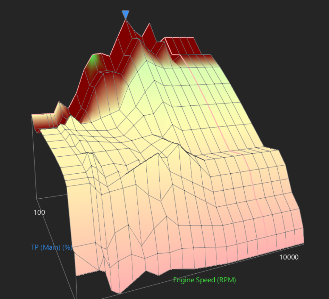
I have started dialling in fuel a bit better with 2 or 3 full throttle runs so far. No cam advance, just setting a baseline. The shape of the fuel map / power curve is absolutely hilarious when there is no cam advance. So the peak VE (105%) is at around 5500, secondary peak 7000rpm 103% so pretty good for the dunga stock cams and no cam timing adjustments yet. Gave it a run to 8300rpm. Good news is that as expected the bank to bank difference narrows down as rpm/throttle opening goes up. But. At 2000rpm full throttle, its only around 55% VE max. It can only half fill the cylinder, so it must be bouncing a big bunch of the air back out. Still sucks until around 4500rpm then starts to wake up. It's also quite gross coming just off idle, as I think it's gaining a huge amount of throttle area quite quickly. Possibly also because I've got a secondary air source that bypasses the throttles (PCV line and brake booster) so it does weird stuff where more air comes into the throttles, but then the reduced vacuum means less PCV. or something. Dunno. It's getting better but it's been the hardest motor to tune so far. I think mainly because the injector position sucks. Will definitely look at doing some explorative drilling on my old heads to see if I can mount the injectors further down. It will be interesting to see how the exhaust cam timing will like to be adjusted as well, as I've never played around with that before. This graph isnt suggestive of final powerband at all. I am just posting it because it's comical to see how much this engine sucks shit with fixed cam timing. I suspect that the home position of the cam is hugely far back, so it's working kinda like the atkinson cycle on the 1NZFXE. So its trying to reduce pumping losses as much as possible by having the cam intake timing incredibly delayed. People say that the Mark X gets exceptionally good fuel economy for a big barge, so this is probably one of its tricks. It's also probably why it cranks over fairly easily with 12:1 comp as well. I bet it would read surprisingly low on a compression test. The low end should jump up by heaps with even say 10-15 degrees of intake cam timing added.
- 131 replies
-
- 24
-
-
-
Yeah I can see that. So did some top level science today. I put a spatula type thing over one of the muffler outlets. It cuts down the bassy noisy by heaps and the tone changes a fair bit. I'm thinking the secret sauce is probably to do with keeping the exhaust pipe diameter small, then just adding more pipes if you need more flow. Reason I think this, is most factory cars have small diameter pipes. Then when someone puts on a big bore exhaust, it gets a real deep tone. I think one component of the exhaust noise that you cant change is the frequency that relates to how many rpm you are doing x how many cylinders you have. But then secondary to that, I think the tips probably resonate at a frequency relating to cross sectional area. Some supporting evidence: Motorbikes usually have small dia pipes and sound great. Zonda has 4x smallish pipes and sounds incredible This other zonda has 4x smallish pipes and same deal Then here is a zonda with only 2 pipes, that sounds like absolute bucket of shit: (grading on a curve, for having started with one of the best sounding exhausts on the planet) Four small pipes:
-
Yeah it's only got a single muffler on it at the moment, so I guess not very refined or whatever / worst case scenario. I'm glad the noise level is down though, and I can at least start putting the tune together decently. Buuuut yeah. needs work.
-
I've been chipping away at a bunch of tasks and tidying things up, after the excitement of first drive has faded. But one thing on my mind which is - Man I honestly hate how it sounds at the moment. It's not right for the car at the moment and not very pleasant overall. This car has only had two objectives... Do a shitload of rpm, and sound cool. I've been fixated on sorting out the nuts and bolts of getting the motor fitted and running. Then dealing with some "shitload of rpm" problems. But the current noise even just idling. Just seems so discordant to the rest of the car. It sounds like a straight piped AU Falcon or lil johnnys RB20DE. Honestly, I have looked up on youtube some straight piped falcons and RB20s and it sounds just the same haha. How to improve? Here's what I'm hoping: -Will sound better once I've got the fuel map sorted a bit better, and some cam overlap chucked in there -Will sound better once trumpets are on (was just bare throttles currently) -Will sound better once it's doing a full throttle nang up the road -Will sound better with big cams in it -Might try keeping the 2-1 pipes smaller diameter, (currently 3") then flare out to 3" -Will try some different muffler options -Might try splitting exhaust back out to 2 pipes -Smaller tip diameters on the muffler (currently 1x 3" in, 2x 3" out) Ideally want to get rid of the bassy exhaust note a bit. Given the variety of sounds that I've heard from 2GR exhausts, I dont think it's an insurmountable problem. If I had a broader vision for the car than the two factors above, I could forgive it for sounding a bit "meh". But this is the one thing that will drive me mad if it's not right. Currently sounds way worse than a prius motor did - Surely that's a fairly low bar to set! haha. Still stoked to do some skids in it, but really looking forward to getting the tune more dialled in and seeing where the torque/power ends up with current setup. Then cant wait to chuck the big cams in and see how it compares. I will go back to listening to Alfa 155 DTM noises while my faith in V6 wavers...
- 131 replies
-
- 26
-