

kempy
-
Posts
2,352 -
Joined
-
Days Won
2
Everything posted by kempy
-
How much fuel do they sample? It was only 100mls or so back when we were doing oil and fuel samples, but some things might have changed sine then. I don't use a heck of a lot tbh. Still... free fuel is free fuel!
-
Alex and Hannahs bushblock shinanigans. Look at my deck..
kempy replied to yoeddynz's topic in Other Projects
Geez you guys don't muck about!, living the life though, very cool indeed. -
it probably could, it runs on jet-a1,avtur is jp-1 which no longer exists along with jp-2,3. Jet-1 is the same as jp-8
-
another wee step closer, some of the detail. Dusted off the drawing board, been a while and no compass for drawing radius's, but an old radio knob came to the rescue.
-
Auckland OS Winter shed tour - Saturday 11th July -
kempy replied to Threeonthetree's topic in Upper North Island Region
Great addition to the tour threeonthetree, love yer work. -
You mean you can't even pre-wire the place before signoff, or is that to liven it up?
-
Jonnyfive, Just a hobby, keeps me off the streets at night Pusherman drop in, happy to share a few tips if you have a live project.
-
Went to Saeco bearings and ordered some new ball bearings. For future reference in case anyone needs the info: Pedal Ball bearings are 5/32", 11 balls per cup. Steering ball bearings are 5/32" , 16 balls per cup Crank ball bearings are 1/4" 9 balls per cup Will update with wheel bearings when I get to them unless someone else still has the info?. Grease, I'm using a Lithium Complex EP2 as that's what I had in the shed,
-
Cool, yeah I have the side in me which says replace replace, but then there's the "it's just a bike you'll use once in a blue moon" bit, I'll get the bearings and see how it feels, it it pisses me off then I'll get a new crank/cups. Leaving it looking rusty has been a challenge for Mr. ooh shiny bead blast it, chrome/paint
-
Can you get such a thing for bikes this age? the cups are just cut into the crank so it would mean a crank replacement.
-
Started to strip it down tonight so I can get measurements spot on and do a bit on maintenance. With a bit of a scrub it should come up pretty well, don't think I'll even bother to paint completely, just a couple of patches. Any Idea what the colour might be? Crank bearings are poked, what's the go can you buy replacement bearings, balls or?
-
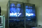
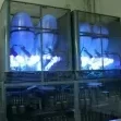
With the board unsolder-ed from the transformers, I can now start the re-capping process. First up will be the black "Hunts" capacitors as I have suitable replacements in stock. I'm lucky to have a good stock of old "mullard "capacitors to replace them with, they hardly ever fail and are hard to get, also quite desirable to guitar amp builders. They are also can be named "Mustard " capacitors because of their colour. I'm using them as they don't look out of place unlike the new yellow ones either side of them. last one for tonight, Here's the "Hunts" capacitors removed. You can see from the picture that some look a bit worse for wear, they also fail testing on my ESR meter.
- 26 replies
-
- 12
-

-
Next job is to dismantle the amps without damaging it further. The knobs are a snug press fit and the front is easily scratched, so a bit of thin plastic to slide under and pull works well. Front and knobs off The main offenders are the 2 large aluminium can type capacitors, the black plastic looking capacitors and the smaller aluminium type capacitors on the board However to do this I need to unsolder the capacitors from the other side of the board and to do this I have ti unsolder all of the wires going to the 2 transformers on the other side of the chassis. Here's one of the offenders They're a brand of capacitors made in the UK back in the 50's and 60's called "Hunts", most technicians renamed them by removing the "H" and replacing it with a "C", sums it up pretty well..
-
Here's another little project on the burn, I found 2 Pye Mozart amps a while ago and it's time to bring them back to life. They are what is called an integrated amplifier which means the pre-amp (volume/tone/input selectors) is integrated in the same chassis as the Amp. When they were sold in 1958 they retailed for approx. 33 pounds each. I was lucky enough to find a pair of them in reasonable condition Here's a rear view of the amp, plenty of dust from 50+ years of life in shelves and sheds. If you take a close look you'll see 1 large valve ( Vacuum Tube) lying on it's side, the model is what is called a "single Ended" amplifier. What does single ended mean? Strange that you should ask, but ok, I'll try to explain. I'll do my best to without making too many eyes glaze over , single ended means that the one tube is biased to the mid point (with no input) and it performs the whole output section with one tube instead of 2, sound confusing? Lets look at a normal situation using a complimentary pair of output devices, I'll use an example most can relate to; Car Batteries! If we had 2 x 12v batteries and we connect a volt meter lead to the jumper lead that connects the two batteries together, in this specific example that connection point is called the mid point or "0v". - [12v batt A]+ --- 0v --- - [12v batt B] + If we connect the other meter lead across bat "A" then it would read -12v If we connect the other meter lead across batt "B", then it would read +12v (if we put a meter across the 2 batteries (end to end) we would get 24v) The same logic applies to an amplifier, If I had 2 output tubes (or Transistors) 1 tube would handle the -V side of the sine wave, the other would handle the +V side on the sine wave, with them both connecting to each other at the "0v "point, put in a complimentary pair they do the job nicely and allow for very high outputs if reqd. However for a single ended tube we have only 1 output device, so if the maximum output swing was 24v, we artificially "bias" the tube so it sits at the mid point (0v in our battery example), and it can swing up or down 12v to make it do the job Hope that wasn't too confusing. The output tube is an EL34 and this model about 9 watts output at 0.3% distortion @1Khz, which was pretty good for back then. Here's another view with the cover off and the output tube removed, and a quick wipe
-
Good keen man! I remember an ex neighbour speaking of a 18 speed 50cc bike that used to clean up a lot of circuit days, he recalls seeing it locally bit I cant recall who it was. I reckon you'll need one of these at some stage. https://scooterhooter.files.wordpress.com/2014/10/a50_as50_99500-10000-01e.pdf
-
I'm building up a bit of an analog recording facility, just for interest. Reel to Reel, Tape, 8 Track etc. Nice 7 tape unit, haven't seen one of those in ages.
-
Auckland OS Winter shed tour - Saturday 11th July -
kempy replied to Threeonthetree's topic in Upper North Island Region
It's a 2 dayer? Audiodude, you can bring your stuff to show off in my shed. getting it back may be a different story -
No expert but it looks like an ac50 because of the short tank and a high pipe (exhaust) I've got one exactly the same colour, awesome bike.
-
Sweet AC50! nice score.
-
Auckland OS Winter shed tour - Saturday 11th July -
kempy replied to Threeonthetree's topic in Upper North Island Region
All good, SH_T, I better start cleaning it now. I'll make sure the coffee machine is hooked up in the shed. -
Sounds like a story to be told! Nice work guys, looks spectacular. PS like the minimalist gutter/water tank connection
-
Auckland OS Winter shed tour - Saturday 11th July -
kempy replied to Threeonthetree's topic in Upper North Island Region
Option A for me, can't see my shed being of interest to most. -
Another drawing, I like this one better as it's a lot cleaner. Made from 20mm aluminium or stainless tube to allow all cables to be placed inside it with a 100mm aluminium/stainless tube for fuel and pump housing. Yet to decide where to mount electronics and the mini propane tank Concept is that the sub frame has rubber lined guides that fit over the existing frame and the whole thing clamps onto the 25mm adjustable seat stalk, so it shouldn't take more than a minute to remove, aiming for the "strap on a jetpack" design. In theory, the tank should give me about 8 minutes at full noise, 10-15 minutes at 2/3.
-
Just a placement sketch of gear, may be able to reduce the electronics oval tube down in size significantly yet. no allowances for tubes and wires yet, just pencil on paper so far.
-
They're not too difficult to get used to. Fuel pump voltages, fuel/rpm curves and air temp/pressure are the main considerations for setting it up. Once set up with the GSU (ground support unit) its all in the ECU and essentially auto start.