Kimjon
-
Posts
2,353 -
Joined
-
Last visited
-
Days Won
2
Content Type
Forums
Downloads
Events
Gallery
Everything posted by Kimjon
-
Looks like a harley with that amount of offset.

-
Finished it: I've tuned it since this ride, now running much stronger. It's got huge torque, but the tyres on it make the handling feel like your riding a loaf of bread... I'll swap the tyres out and possibly upgrade the handlebars, as its sketchy as fuck to ride. It lacks any feeling in the controls and just loosely goes "about where" you want it to, unlike my other gopeds that handle much better. Anyways - my motor works, so that was my main motivation for this project, so I'm stoked with that!
-
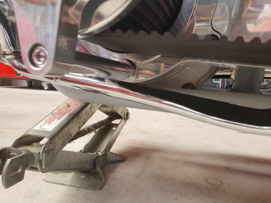
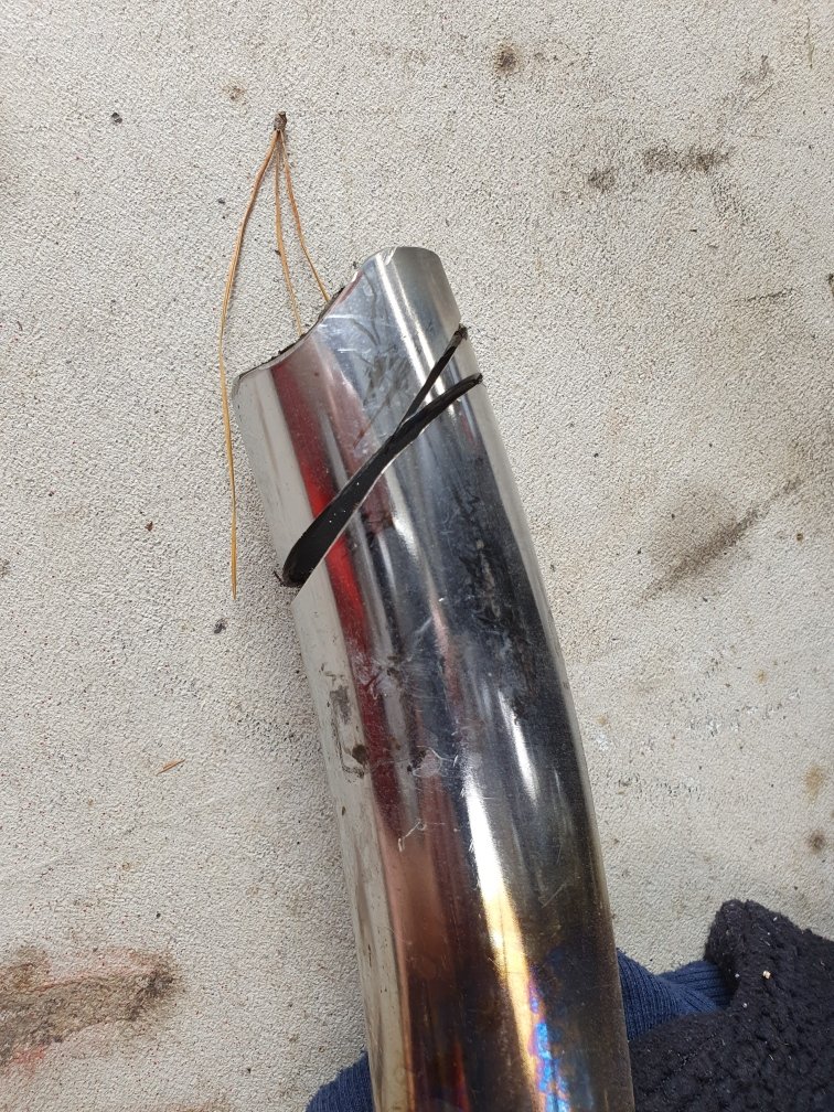
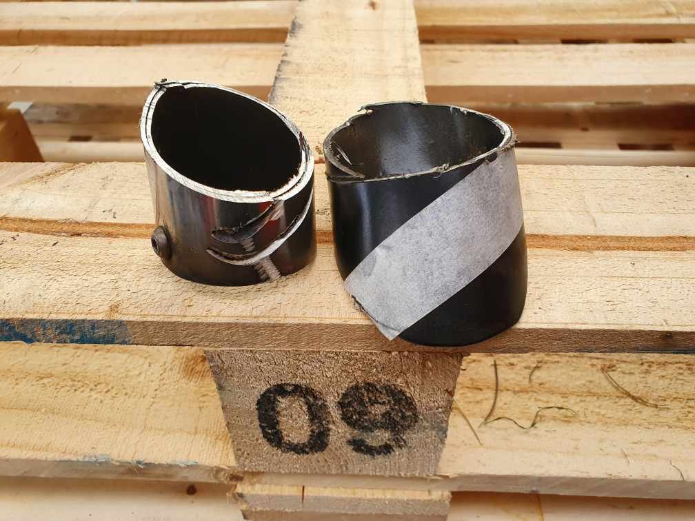
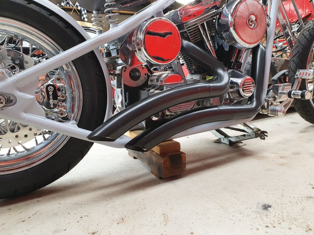
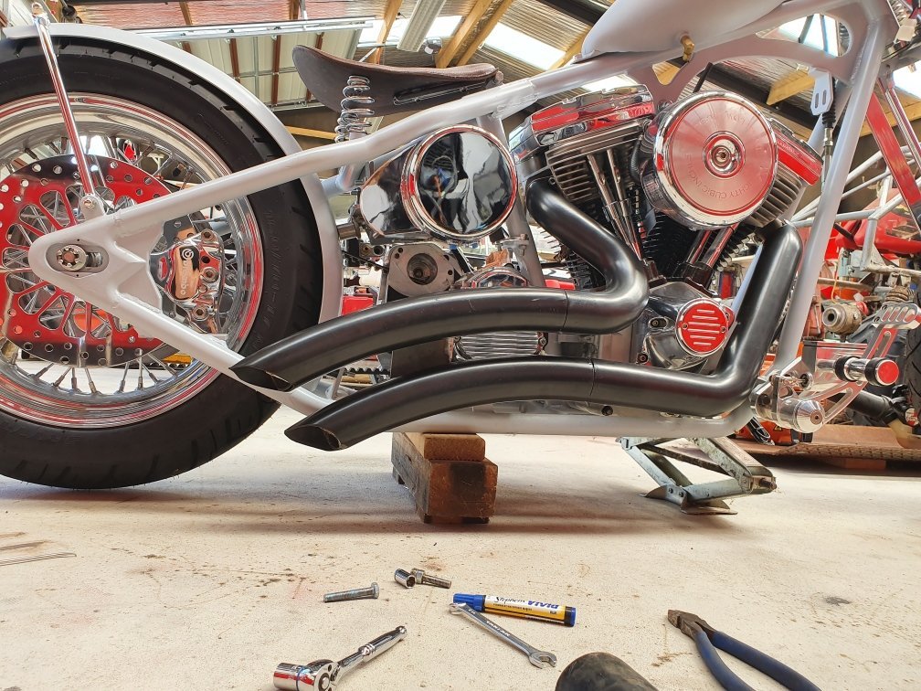
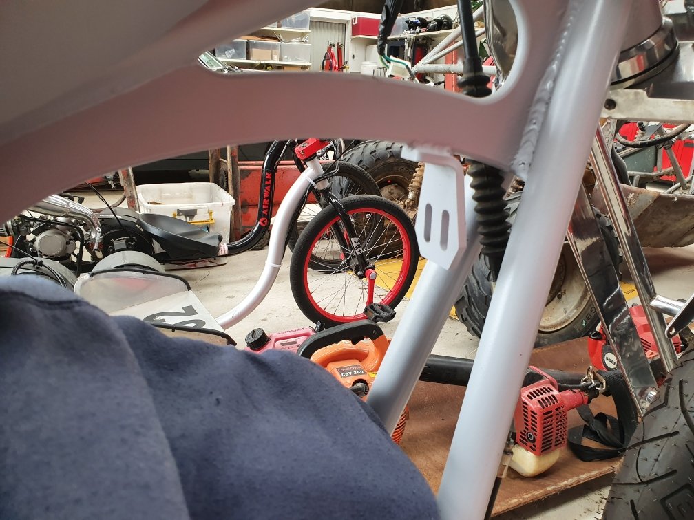
Attacked my exhausts - cutting a fair bit off them, all in order of gaining a few inches of ground clearance. Then I shaped it a bit more to mimic the upper one: Before After Trying to follow the line of the rear leg angle as much as possible. Before After It's just sitting there loosely at the moment, but looking about right. I liked it better before...but there's always a price to pay in exchange for some practicality. I think I would have gained a fair amount of "lean" before it hits now. Probably 10° or more additional???
-
So, funny story to tell. ( @Raizer please read, in case I've given you a bad lead on where to buy stuff from) I noticed my brake lines didn't have printed markings on them, unlike the photos the guy had on his website. So having been through a cert before, got worried I actually have no proof that the lines meet any standards. So I emailed him, asking for something in writing to show he used the correct parts. I got a weird response about how the website photos are 12 years old and manufacturer's don't print id marks on their lines anymore because customers don't like the writing on their custom bikes and that legally he can't show me any paperwork as it breaches his contract with the distributor of the brake line company... (bullshit). So long story short, after a few emails he offered to refund my money. So basically I think the guy was full of shit. Anyway my PayPal account received a credit and I've got my money back. So I'll take my $125 refund, add that to the $140 I was going to spend on the new rear line, and get exactly what I want here in NZ. Over double the price...but all legitimate, not dodgy underhanded tactics.
-
I Googled how the crimping is done. Out of curiosity... Basically it has an inner part, that gets pushed inside the line, like a hose barb. And then the outer part is what you see (on the outside obviously). The two parts are positioned in a machine that hydraulically crushes them against each other locking it in place. Very simple idea, but works great. Unfortunately each machine is only able to crimp a very specific size, so although very close, the guys in Hamilton couldn't cut my fitting off and put theirs on because of the slight difference in the sizes.
-
Apex brakes in Canada. Much cheaper even including postage it was only $120 for both lines delivered. They meet SAE/DOT standards so all compliant. Delivery took less than a week to my door. I fucked up my side of things. This would have happened no matter where I got them from. The mistake was mine. Tempted to order another set from them, however my local guy has a longer fitting that better suits my needs. So I'll get them to make the rear line with this much longer fitting.
-
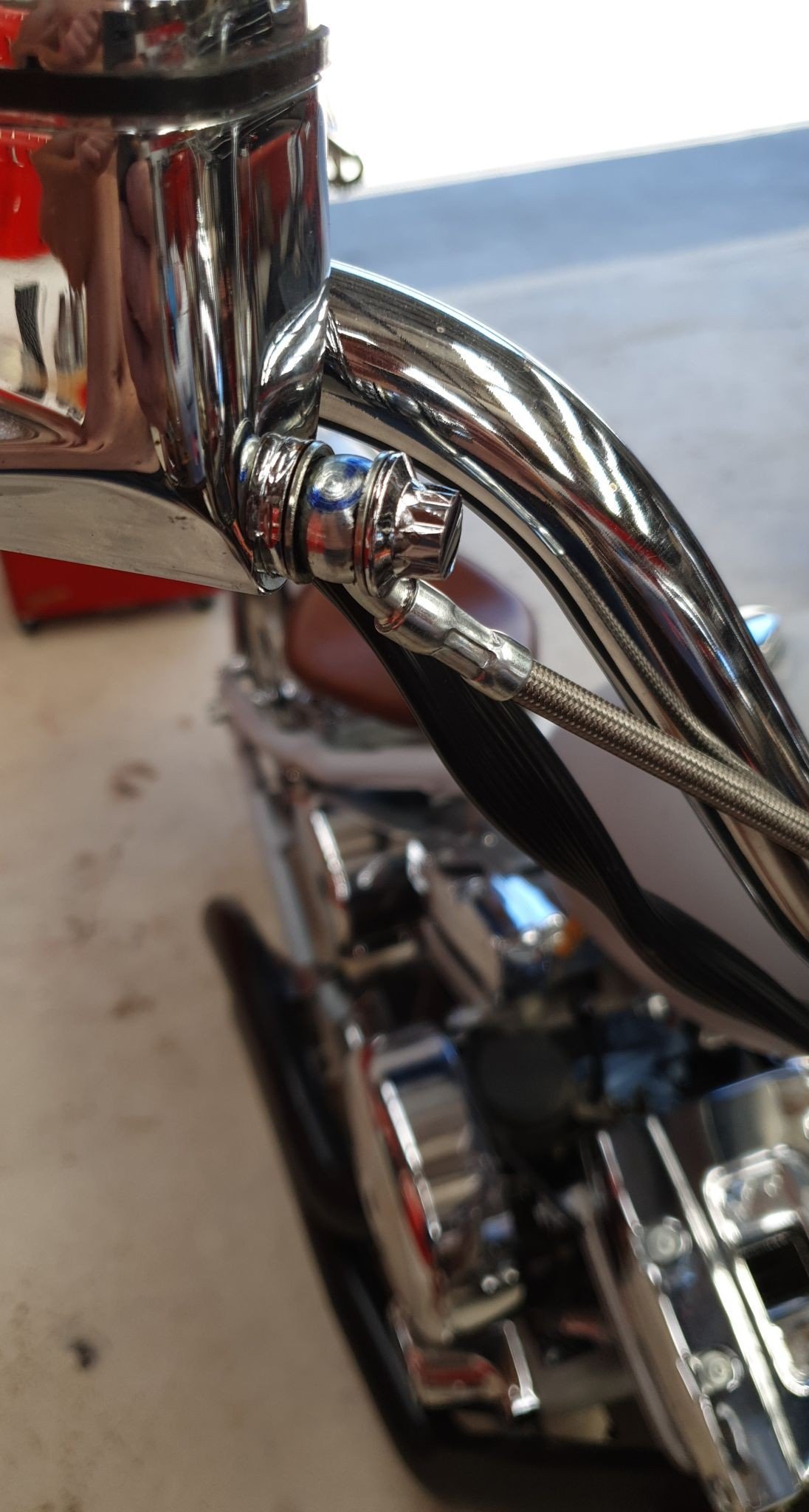
And then opened courier packages and boom... Sexy braided stainless dual throttle cables, made to order. Nice matching set to go with the braided brake lines.
-
Okay, things aren't as bad as I thought. I took the lines into a brake shop in Hamilton. Manager said that drilling out the M10 to 11mm is fine. No problem at all, something they often do themselves in fact. As long as I use quality copper washers and check it for leaks it's no problem. So that's reassuring. The other line that I bent by hand from 90° back to 45°, he said is probably fine too, but a small question mark about the possibility of me over working it. No guarantee that it won't fatigue. So for 100% peace of mind I'm going to replace this line. He has more crimping options that may allow me to get the 90° bend I really desire, rather than accepting a 45° and making that work...so I'll probably get one made ($140-$160 per line...ouch)... but fuck it, I'm living the good life right now and don't want to check out this early.
-
Yip, probably put this down to learning and get them all re-made again. Guess that's the price of education sometimes.
-
Okay, I ordered some brake lines. Custom made to my dimensions I supplied. Excellent service, happy with the product... but perhaps I should have taken more care with my measurements... So this banjo turned out to be an oddball at M11. Balls!!!! Cunt!!! Shit!!! Of course I measured a couple and got M10 (3/8"), so simply assumed they were all the same, ordered all M10. Hmmm 3 out of 4 normally isn't too bad, unless its safety critical. I've drilled it out to M11. I figured 0.5mm off each side won't affect the way it works that much. So I'll get some better washers and was thinking I'd probably just run it like that. But now...not so much. Everything else looks good. The rear. Well I measured it all correctly, but didn't realise how small the 90° bends would be. Unfortunately so tight and small it cant reach the hole in the master cylinder for the banjo bolt. It's short of reach by about 10mm Balls!!!! Cunt!!! Shit!!! So I bent it to 45°. But now I'm stressing that I shouldn't have done that, as it may fatigue crack. So I'm going to take it to a brake place in Hamilton and get them to put a new press fitting on it, for peace of mind. So all in all, a bit of a fail.
-
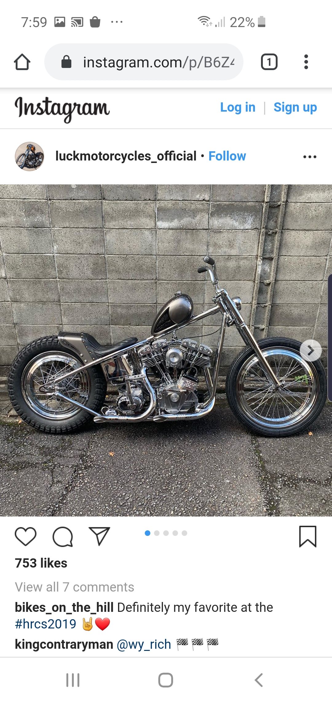
Fuck yeah, I've been a luckMC fanboy for a long time now. Just love their style. I saw one of their earlier bikes about 8 years ago now and saved it as inspiration. They've built a heap more cooler bikes since then, like the one above.
-
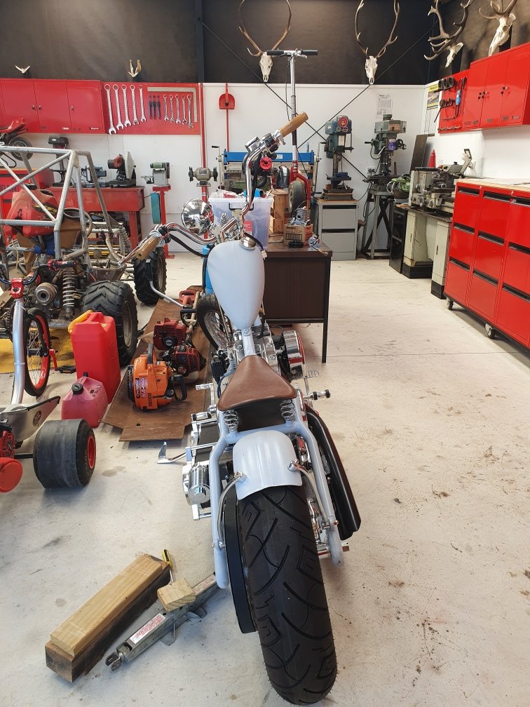
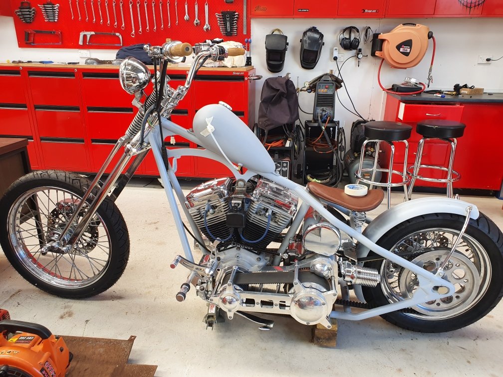
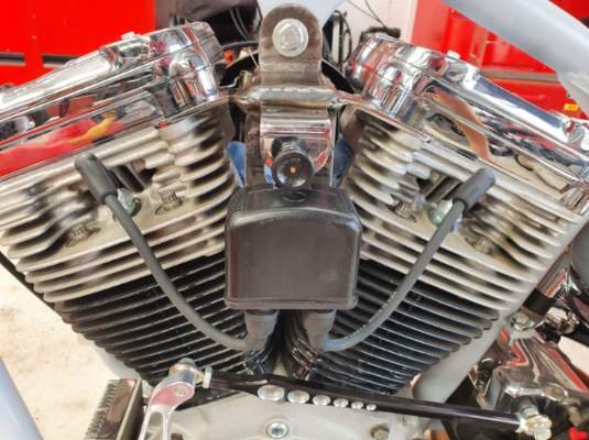
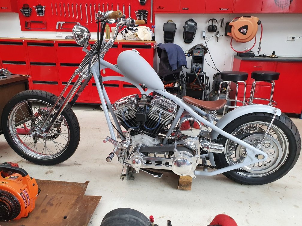
Haha, I'm not feeling the love for sight tubes eh. Moving right along, I cut the coil tab off, now that its relocated to another place. And gone: Much better! It really opens up that space. I've always thought my tank was just a touch too long, but by opening up this space by removing the coil bracket it changes the proportions and makes the tank appear a touch smaller. I love this look, with huge gap between tank and neck of frame. The Japanese are making some of the baddest bikes on the planet these days. I love their edgy style and ability to push the styling limits.
-
Just doing a bit of Google research on tank sight tubes that don't suck. Yeah, yeah..."blue and green should never be seen" (together). But both these bikes pull off a sight tube that looks okay. Still not ruling it out...
-
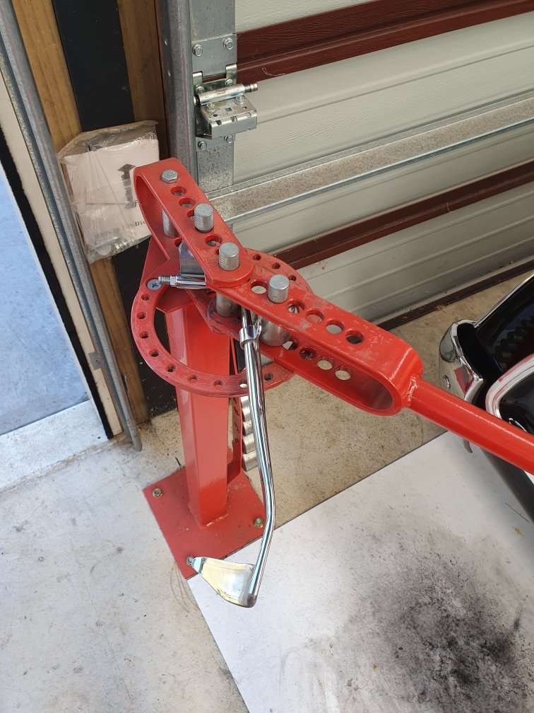
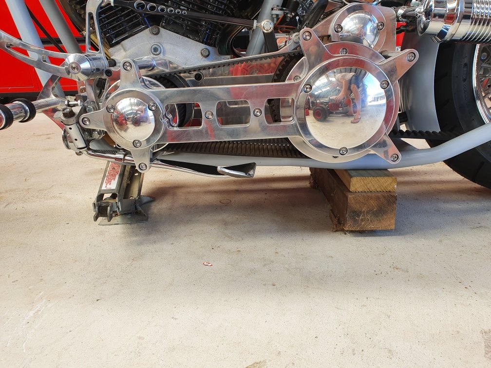
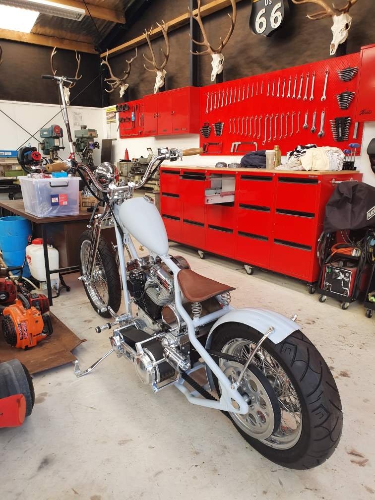
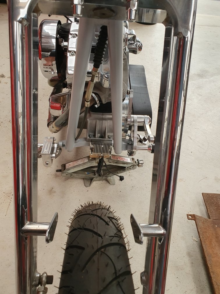
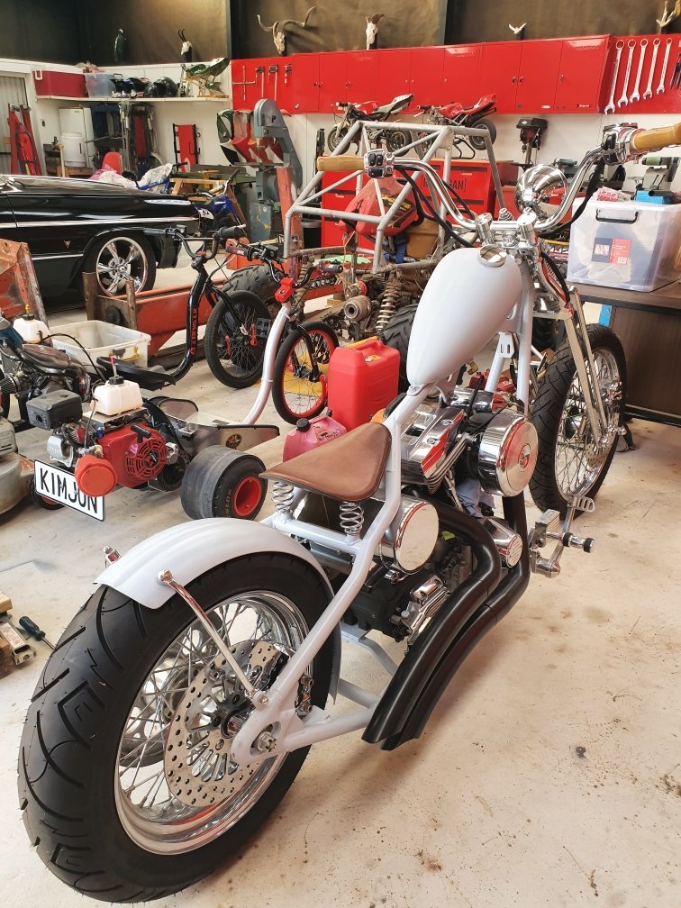
Yeah, I'm on the fence. I like the retro idea...but I'm not married to the idea yet. Will park it and see how I feel in a few weeks time. Moving on with other things that are within my control and don't cost money to do because I'm brokeass right now: Bending the kickstand, so it both leans the bike over more and tucks up higher when not deployed, for extra ground clearance. Its sitting tight now. Only about 3mm gap. Before it was about 15mm from hitting the drive belt cage. The tip has lifted up about 50mm from the ground. Calling it a win!
-
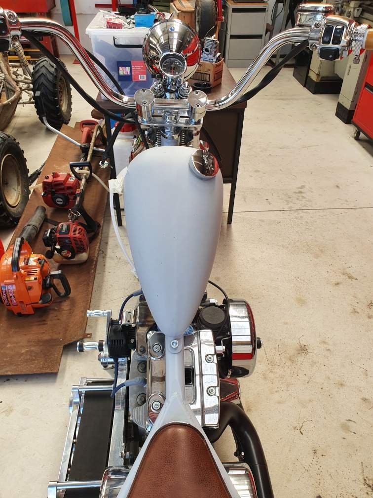
Toying with the idea of a sight tube, so I can see where my fuel level is at without having to run empty, or stop and look into the tank. I don't think I'd purposely ride past a gas station without stopping anyhow... 1340cc big cammed motor Vs tiny gas tank = stopping often. However having a visual of my fuel level can only be a good thing? Something like this (just mocked up with inappropriate parts for a daydreaming session). I'll give it some absorption time, and come back to it later if I still like the idea?
-
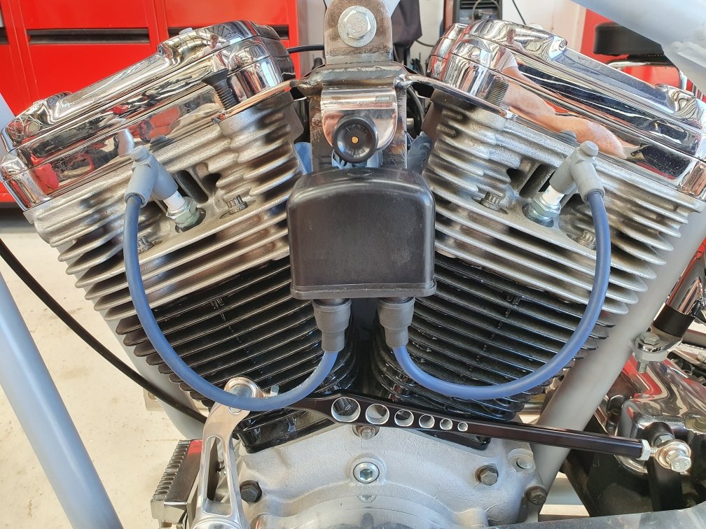
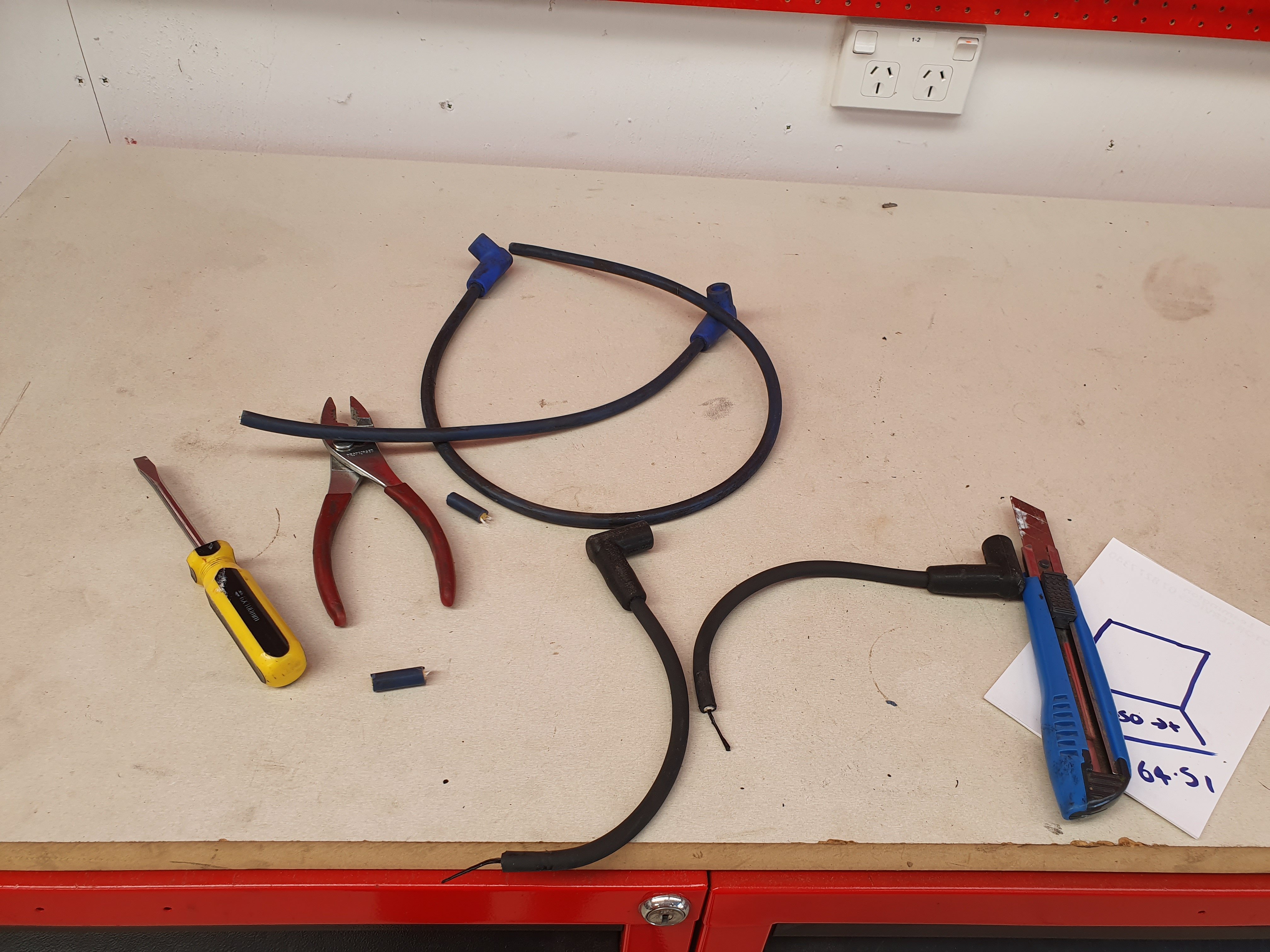
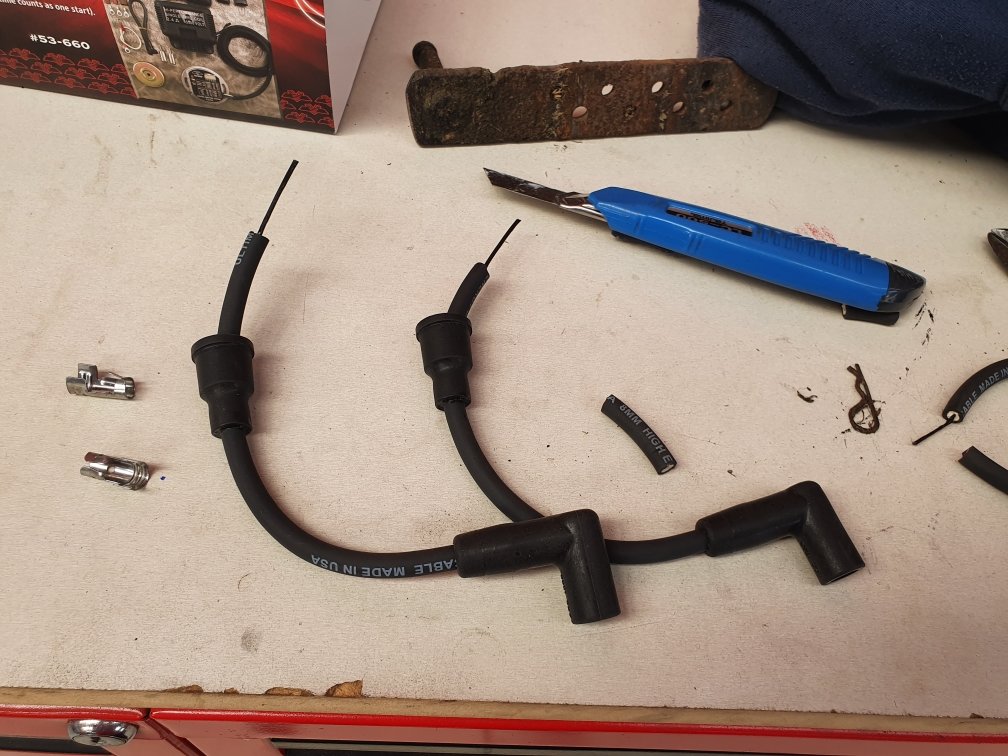
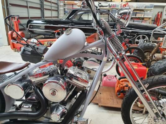
Thanks @Lord Gruntfuttock for the good advice. I kind of knew that I was pushing the limits with those short leads. I cut them down in stages trying to make them as short as possible...but was probably asking for trouble down the track going that short. And tadah! So I made some new ones out of my old impala HT leads. Thanks Mike, for leaving them with me after generously giving me a new set of leads a while ago... kind of cool these leads are now living a new recycled life on a harley...
-
Yes, I think they are an inch too short. Oh well...guess I'm going to get lots of practice making leads eh...
-
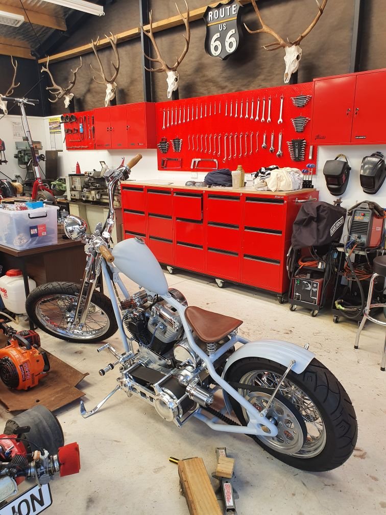
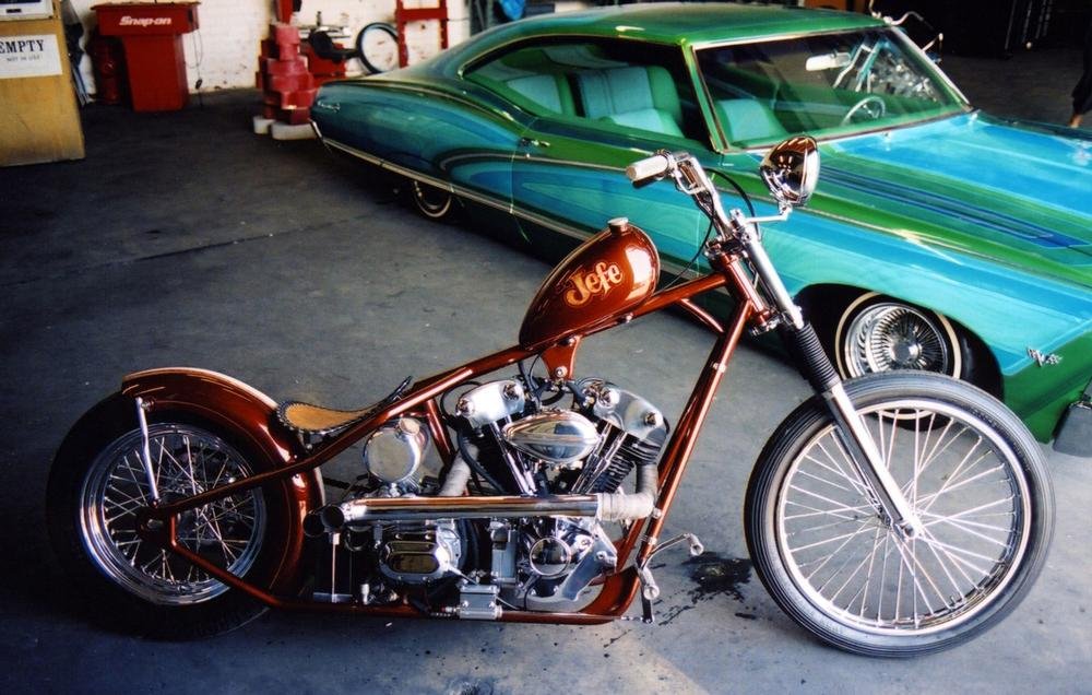
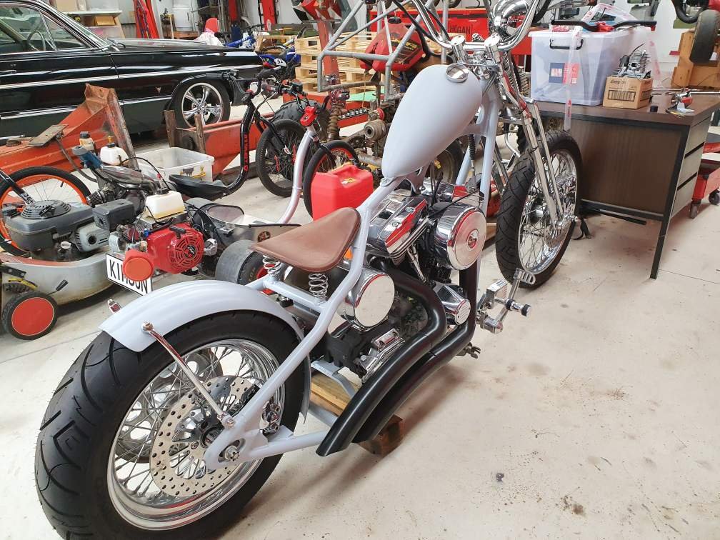
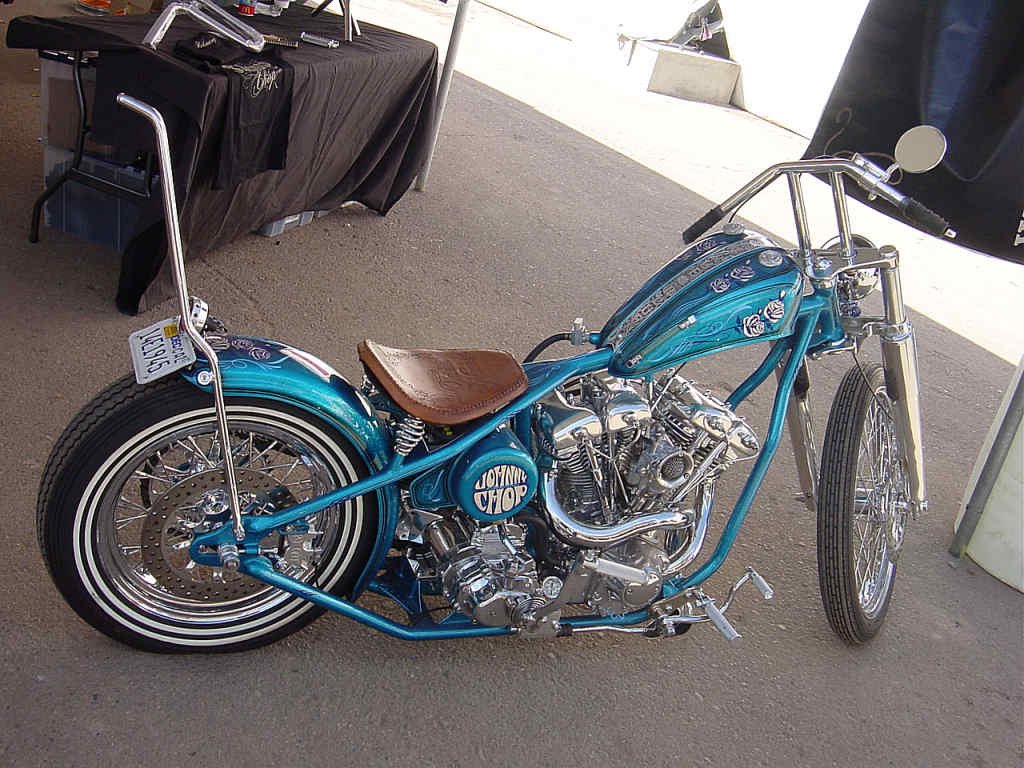
Short answer is yes, totally legal (will need cert obviously). And thanks, admittedly its dragging on a bit - progress wise. But it's a weird project in the fact I really don't need this bike, so I'm taking my time and enjoying the journey. I've always wanted to build one since seeing one in an easy rider magazine about 30 years ago... to be fair I was more into the naked girls within the covers of those magazines (pre internet days), however a rigid chopper caught me eye and I was in love! The single most important thing is the straight line from the bikes neck right back to the rear axle, this to me was what caught my eye all those years ago and makes these bikes what they are. The secondary things I like are the proportions. By playing with the amount of stretch in the frame, the amount of lift in the frame, the length of the forks, the gaps between seat, tank and neck, the size of the tank, the amount of rear fender you choose to keep...all those things drastically change the look. This is my all time favorite bike. The builder (Superco Custom, Trevelen Rabanal) pushes the proportions to the edge, but in my opinion has built a masterpiece. I've taken a lot of inspiration from this bike...but still trying to achieve my own vision too.
-
More inspiration shots: Things are falling into place. The progress is slow...but at least shits gettin done.
-
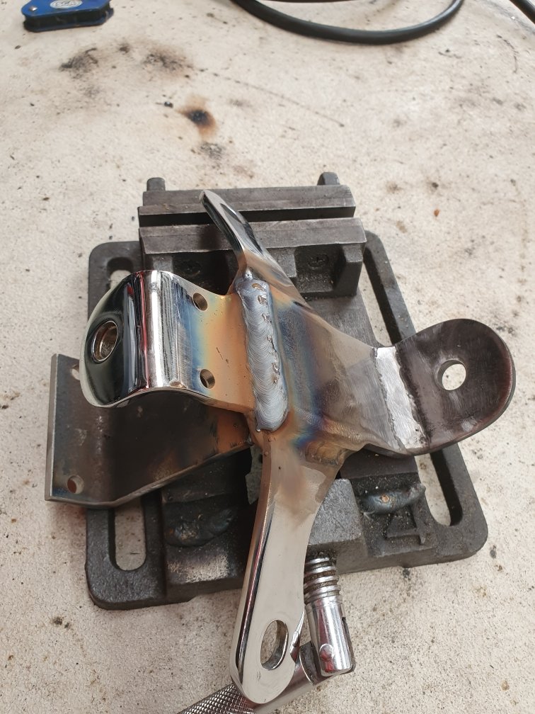
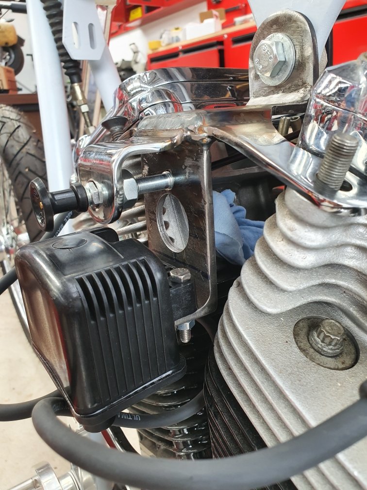
Bit more fab work done today. Getting down to the stuff you don't want to admit a motorcycle needs to run. All the ugly stuff that detracts from your previously clean lines. Oh well, its gotta have it...so may as well face up to it and get it done: Welding more brackets to other brackets, that were welded to yet another bracket? I drilled a few holes in it. One for function...the other for looks. Test fit. Then I made my own HT leads up. I'm pushing it...but I wanted them as short as possible. Just scraping in, definitely wouldn't want them any shorter. Booyah!!! It works.
-
If you're handy to the waikato you're welcome to use my mini lathe if you don't have access to one already.
-
Random slightly cool stuff you built but not worth its own thread, thread
Kimjon replied to h4nd's topic in Other Projects
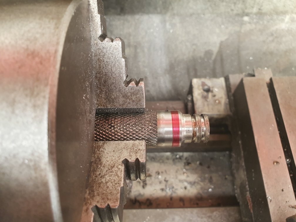
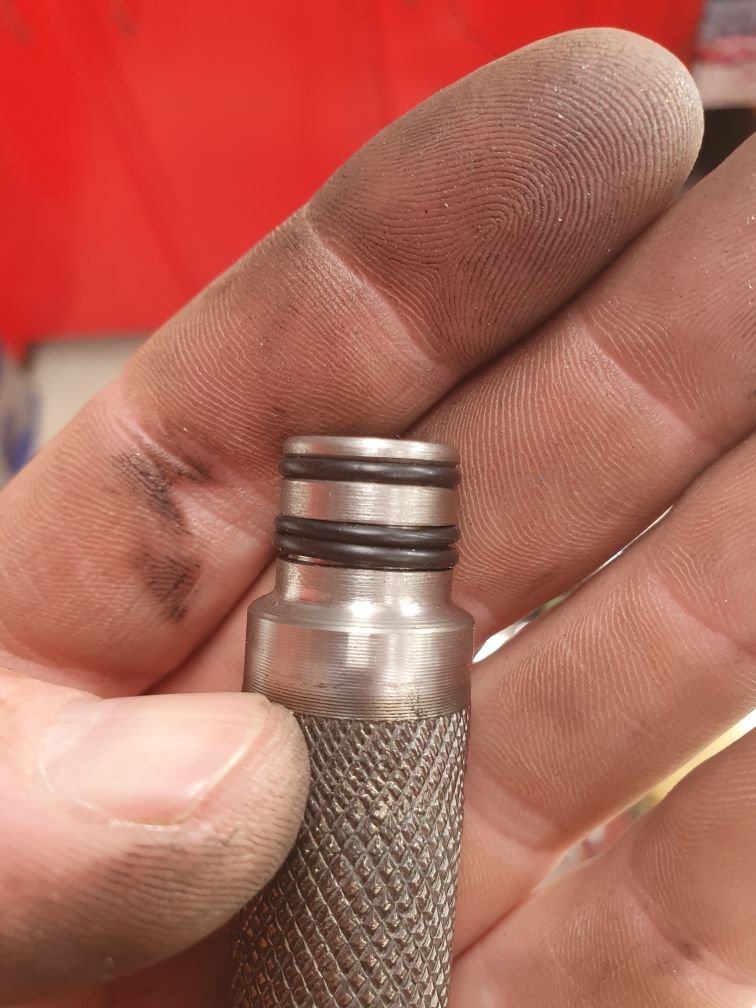
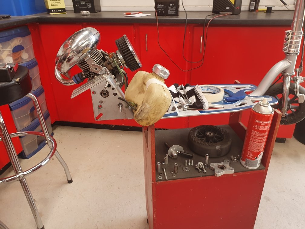
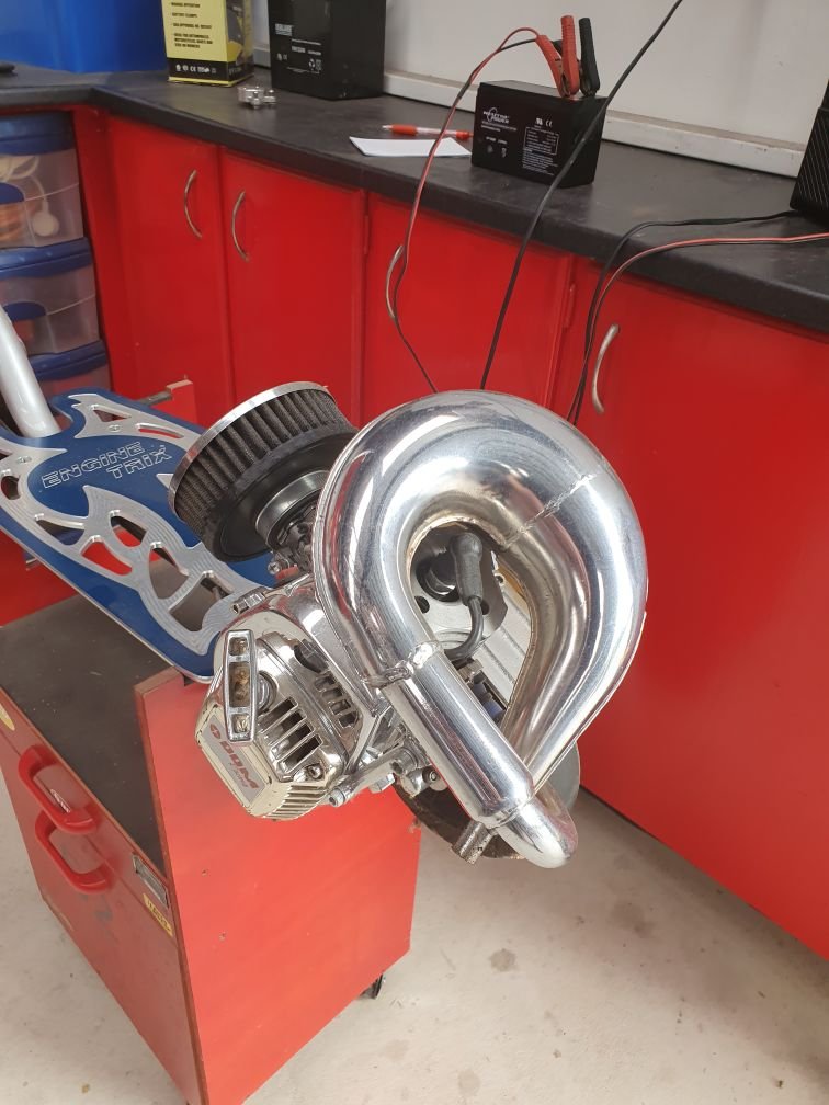
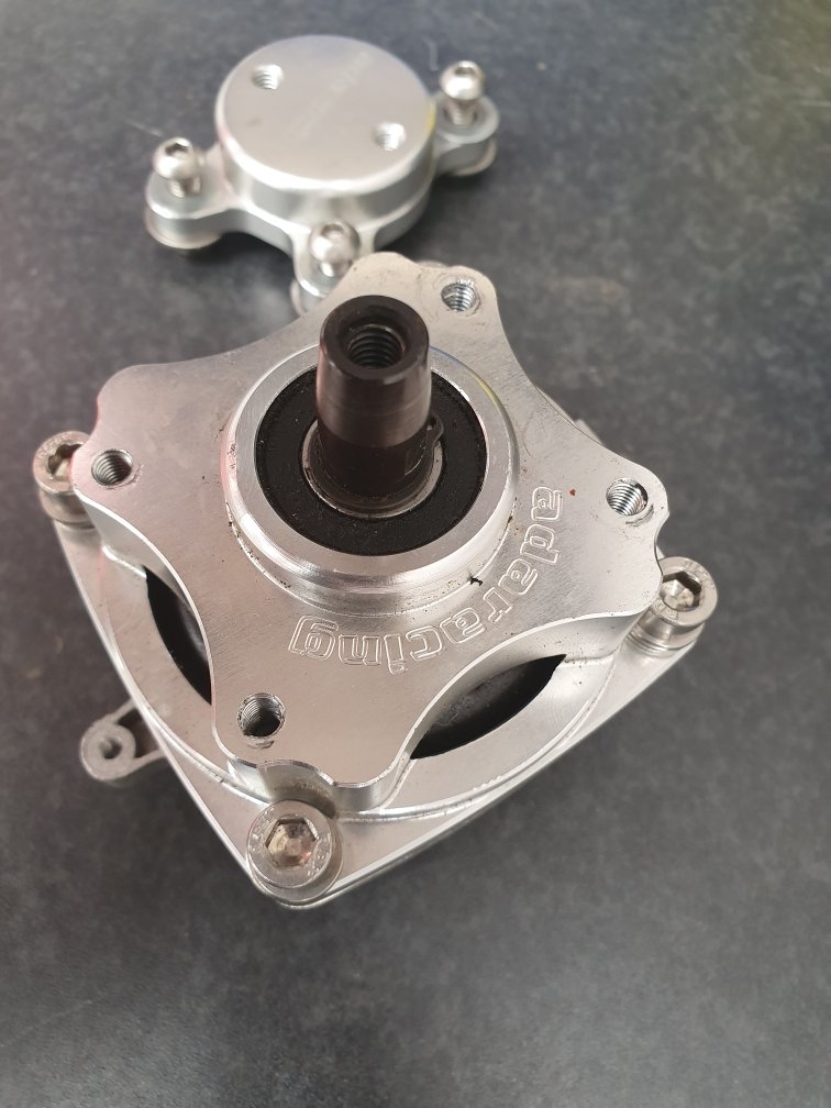
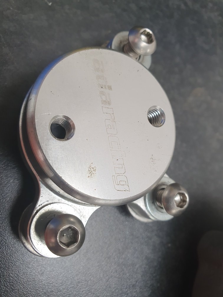
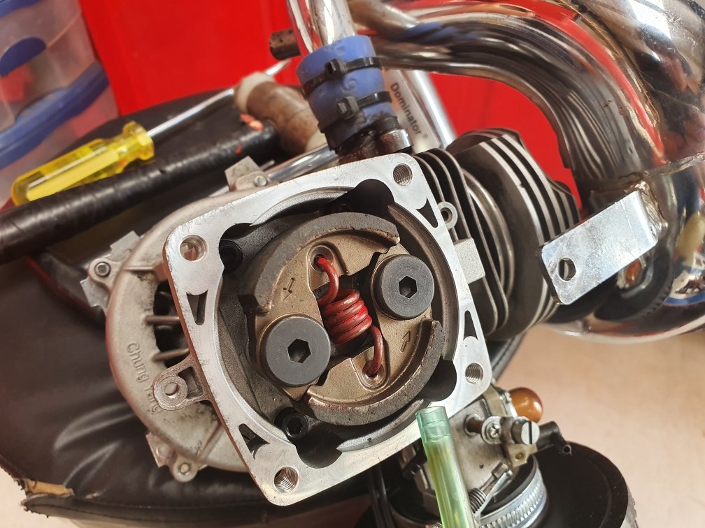
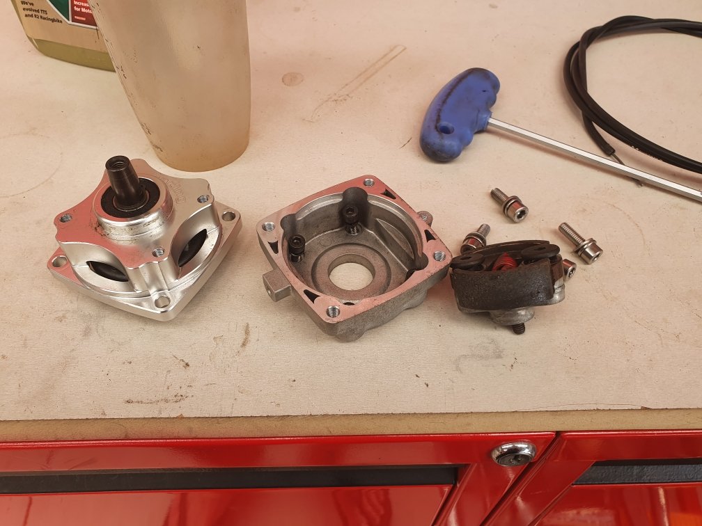
Added a clutch to a goped, so it's no longer direct drive. I can come to a stop and the engine can keep running, then go again. Normally gopeds are direct drive, so if the motor is running you have to be moving too. If you stop completely, then engine stops. Until now: This is something I've wanted to do for over 24 years ever since getting my first goped, but price and availability were always a bit of a barrier to achieve. Pictured are the clutch internainternals mounted in place. ADA make a kit that converts it to a 54mm clutch, and a cnc machined adapter that gets it to go back onto the frame with the right spacing. Sweet bit of gear, pretty high end stuff. I had to make my own spindle to convert it to take a 3rd bearing support, but it was a pretty easy job having done a few of them now. Weird lifetime goal to have...but i feel like I'm clocking life right now!
-
Yes, 1:1 ratio motor to jackshaft, then clutch to axle/wheel. Sorry, I was assuming that you were doing that.
-
Yes, as long as gearing to jackshaft is 1:1 ratio. If that's the case it's no different. If gear ratio differs, then your engagement rpm will reflect the difference. It may still work fine, but something that you need to consider. I normally cut about 10mm of spring out on my lower powered drift trikes to raise the spring tension and in turn raise engagement rpm up for the clutch. This is similar to raising rpm on a car and then dumping the clutch = faster take off and wheel spin goodness.
-
@Muncie have you seen this kids channel on YouTube. He makes cool stuff, especially given his age. Think your motor is the same or similar?


.jpeg.d663a5ec0bd0202ebe502f4301c08ce2.jpeg)