Flash
-
Posts
1,717 -
Joined
-
Last visited
-
Days Won
2
Everything posted by Flash
-
Not a bad pre WOF result, so hopefully you are able to get it all legal shortly. Chuffed to see that you have removed that fake grill. It spoiled the classic Imp front end look in my opinion.
-

SR2’s 1947 Vauxhall “Rigamortice” Discussion thread.
Flash replied to sr2's topic in Project Discussion
Jeez, slow down Simon. You are making the rest of us look bad LOL. Seriously tho, good work mate. You are steaming through it now. -
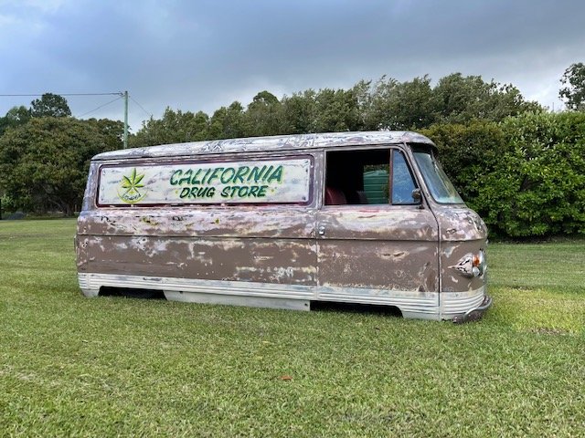
In other news many of you will remember the green Mitsi Starwagon that gave up its front suspension for the Thames. Well the engine and 5 speed manual gearbox from that van made their way down to New South Wales and have been given a second lease on life powering along this bagged Commer van. Mick the owner took the Commer along to this year's Summer Nats where it drew heaps of attention. Looking at this photo its hard to believe that there are a set of wheels lurking under there somewhere.

- 740 replies
-
- 17
-

-

-
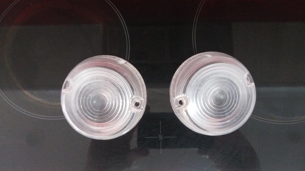
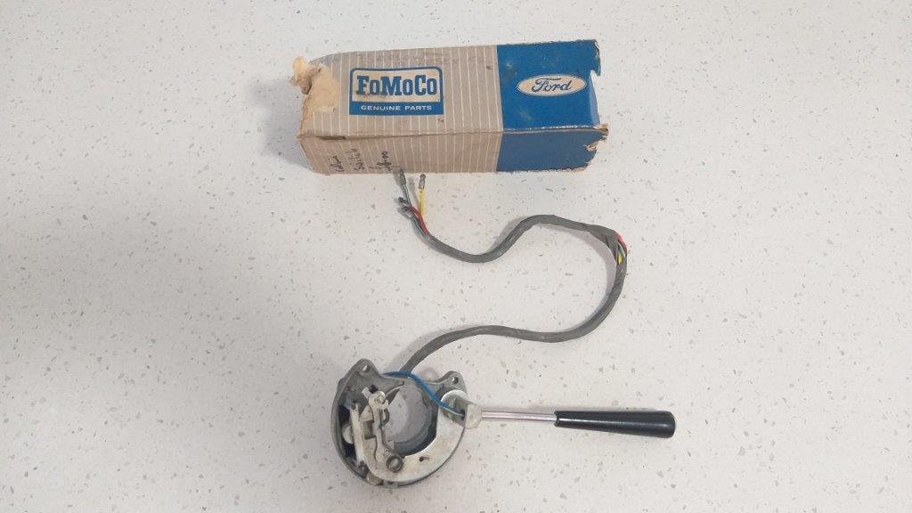
With the Mustang hogging most of my car time these days the poor old Thames has just been languishing in the shed, but she is never far from my thoughts. In the November edition of the UK Thames Owner's Club magazine Sandy announced that after over 30 years of running the club almost single handed he is stepping down for a well deserved break. So with the future of the club being so uncertain I decided it was an opportune time to order the few remaining parts that are unique to the 400E range. These left the UK in early December and arrived safely down under two days ago. The clear park light / indicator lenses are a 400E only part and I was lucky enough to grab a pair of NOS ones as well as a NOS indicator stalk. Its always such a pleasure when it comes in its original box which has somehow survived for almost 60 years.
-
Thanks for the offer @logan360 but I'm across the ditch in OZ so freight would be a killer.
-
Thanks for that @kicker. It's worth taking a look at.
-
Spent some quality time meandering around my local wreckers this morning. Chucked my measuring tape on every set of twin factory fans I came across without any luck. I even went through his stash of loose ones in a nice cool corner of his shed. Looks like most of the Ford and Holden setups are at least 600 mm on the longest side. Even the little Japper and Korean cars have shrouds in excess of 600 mm wide. A bit of creative shroud trimming is not going to get me down to 465 mm being the width of the Mustang radiator. The Mustang radiator measures a piddly 465 wide by 440 high so is a pretty compact unit. Fitting a wider radiator entails removing the factory battery box and massaging the front metal work which is something I'm not prepared to do I can get a few single fan shroud setups within the Mustang dimensions, but the fans are around the 10 inch diameter so are really piddly. So looks like a good quality 16 inch single fan with a custom shroud might be my only option.
-
Thanks @transom. I'll add AU fans to my shopping list at the wreckers. @vk327 that's a really good suggestion. The condenser is a good bit wider than the radiator so I might be able to get away with a pair of smaller pusher fans on either side of the bonnet latch support and I like the idea of having an emergency backup that I can connect up to get me home.
-
Sincere thanks @ajg193and @vk327. I appreciate the input. I'm planning a trip to my local wreckers tomorrow anyway so will take along my tape measure to see what I can find in terms of dual OEM setups. My radiator is pretty small, but you just never know your luck. Yep, the Spals are pretty spendy, but if I'm forced to go single I'd rather invest in something fairly decent. I'll report back tomorrow.
-
Hi Team, I'm in need of some sage advice from those who are knowledgeable on the subject of 12 volt thermo fans. Until yesterday my 66 Mustang was fitted with what looks like a factory 5 blade mechanical fan and an aftermarket plastic shroud. I suspect that the previous owner may have been experiencing engine temperature related issues and had removed the a/c condenser that usually sits in front of the radiator and replaced it with a supplementary 12 volt pusher fan controlled by a thermo switch. Whilst this setup seems to work okay, I'm wanting to reinstate the a/c condenser and unfortunately there is not enough space between the bonnet catch upright and the radiator to run both the condenser and the pusher fan. Yesterday I removed the 5 blade mechanical fan and am now temporarily running the single pusher fan only. With this setup the engine temp seems normal even with the car stationery. My initial thoughts were to run a twin set of 12 volt puller fans attached to the engine side of the radiator, one controlled by the thermo switch and one controlled by the a/c. However, checking my radiator dimensions today I'm now reconsidering my options. The radiator seems to be a 3 core aluminium jobbie but it only measures 465mm wide and 440mm tall, so not a huge amount of surface area. So to my simple way of thinking I've got two options. First option would be to run 2 fairly small diameter puller fans, one controlled by the thermo switch and one controlled by the a/c switch. This would give me a level of redundancy should one fan fail. Downside would be that only one fan would provide engine cooling unless the a/c is running. Second option would be to fit a single kick ass 16 inch thermo fan (something like a Spal or a Maradyne) that I would activate with the existing thermo switch as well as an override switch attached to the a/c system. Upside would be good engine cooling even if the a/c was switched off. Downside would be a single point of failure should the fan go tits up. I'd really like to hear opinions on which setup would be optimal. Thanks heaps in advance.
-
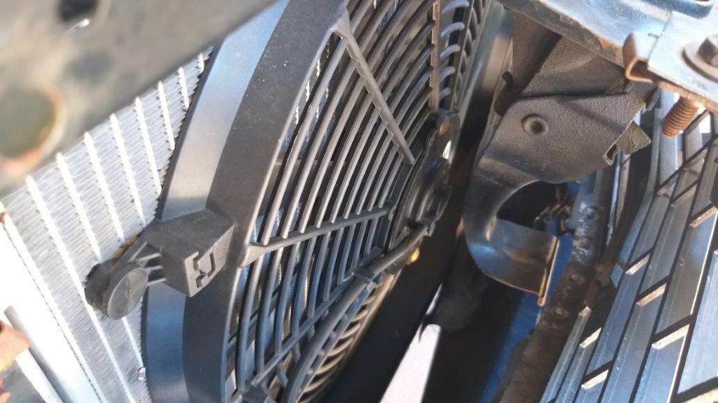
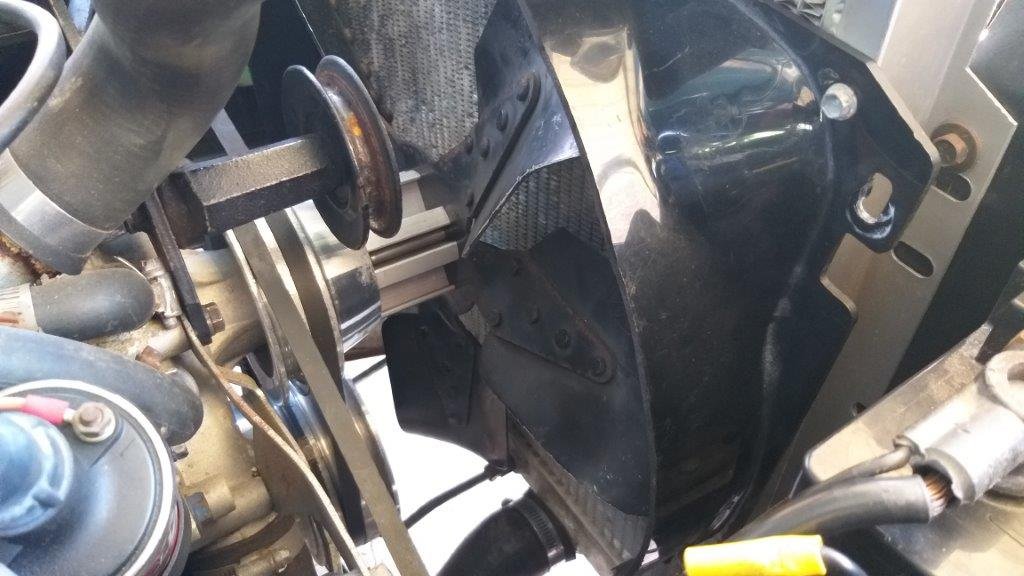
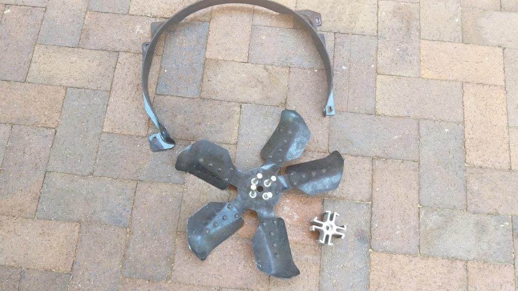
So I turned my attention to the other side of the radiator. Noticed there is a crappy looking conventional fan blade fitted with a ruddy long spacer and a cheap plastic radiator shroud that has been butchered somewhere along the line. Nice ! From factory the a/c had no helper fan and from what I've been able to ascertain from Uncle Google the setup just relied on the standard engine fan moving air through the condenser when stationary. Not ideal as far as I'm concerned. I'm not a fan (excuse the pun) of the manual flex fans and still recall our maiden voyage in our Bedford van down to the Beach Hop when I first fitted the 350 small block. I just had a flex fan at the time and I started sweating bullets watching the temp gauge steadily rise into the red when we hit traffic on the way down. Upgraded to twin electric fans and never looked back. So what I'm thinking is to bin the manual fan blade, spacer and crappy shroud and to chuck in two electric pull fans. One I'll keep on the existing temperature switch and the other I'll connect up to the a/c. Here in Queensland we pretty much run a/c in our cars all year round, so its likely both fans will be running most of the time anyway. So to prove my theory I started off by removing all of the manual stuff and just left the electric pusher fan in place. Took the Mustang for a quick spin to see if there was any difference in engine temp. Did my usual circuit and the temp gauge sat normal all the way, so I'm almost convinced that the manual fan and half arsed shroud were providing little to no benefit. I've chucked a tape measure on my radiator and on my next trip into town I'll visit my local wreckers to see if I can source a set of dual fans and a matching shroud from some other vehicle. Thanks for reading.
- 198 replies
-
- 15
-
-
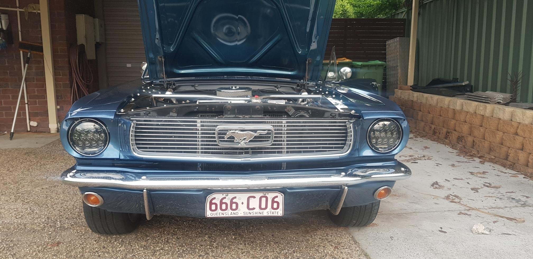
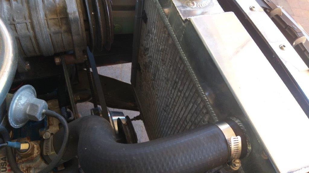
Next job on the list is to re-commission the factory fitted air-conditioning. The previous owner had removed the compressor and its mounting bracket as well as the condenser that normally sits between the front grill and the radiator. Just before Christmas I got a short gap and managed to put the compressor back in place. The drive belt was AWOL so I measured up for a new one which I ordered online. The compressor is a newer style rotary job rather than the factory piston style, so someone has given it a birthday somewhere along the line. Anyhoo, first up was to fit the new belt. Instant fail as its just too short, so I've cocked up somewhere along the line. Measured it again and I get the same measurement so obviously I'm doing something wrong. No matter as what I ordered is a match for the power steering belt, so at least I've now got a spare and I'll order in a longer belt for the a/c. Thought I'd move on to re-fitting the condenser and this is where it gets interesting. First thing that I noticed is that the PO has put a pusher electric fan in the spot where the condenser usually sits and even if I sandwich the condenser between the pusher fan and the radiator there is no way that I will have enough space to be able clear the bonnet catch panel.
-
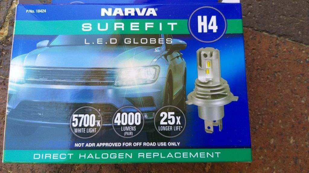
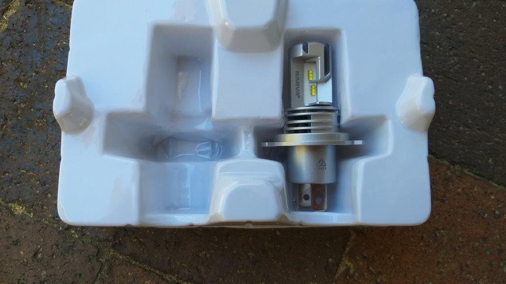
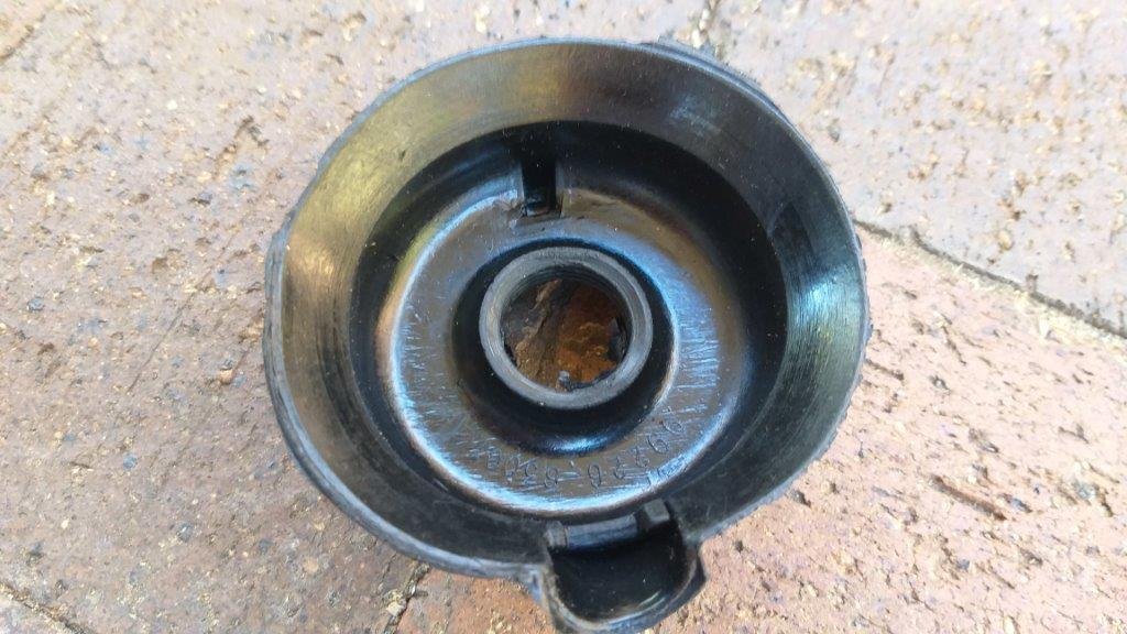
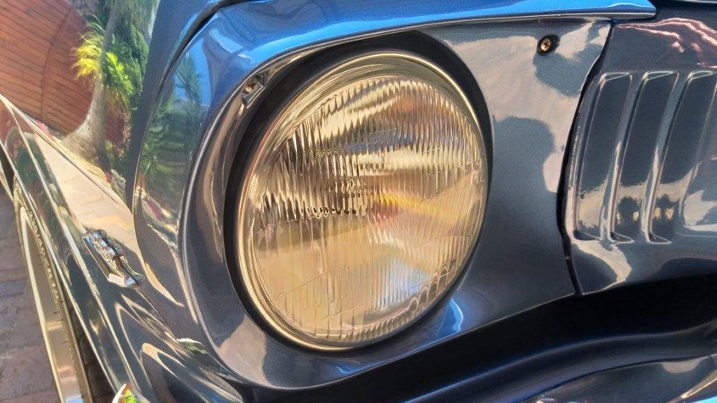
Yesterday was my first day back on the cars, so I spent the morning giving the Moke and the Mustang a good bath. Over the past few weeks I've been gathering a few bits and pieces for the Mustang so this morning I thought I'd start off by fitting a new set of semi sealed beams and Narva LED bulbs up front. First off kudos to @raizer for pointing me in the direction of the Narva LED H4 globes. What a fine piece of kit they are. The box is marked "not ADR approved for off-road use only" but I'm going to pretend that I haven't read that. Only mod I needed to make was to open up the hole in the rubber seals as the LED globes are a bit fatter than the standard H4 jobbies, but apart from that it was pretty much plug and play. Finished off the job by fine tuning the adjustment on the high beams. The light is nice and crisp and makes the old sealed beams look like candle light. Thanks for looking.
- 198 replies
-
- 16
-
-
When we bought the Mustang I promised Mrs Flash that I would replace her garage spot with a secure and dry little nest for her Moke. So being a man of my word I've spent the last few weeks upgrading our back carport which now sports an automated garage door instead of the crappy old swing gates and a nice weatherproof outer wall. I scored the door and motor second hand so had to assemble it myself. Gotta say that in the past few days I've learnt more about balancing garage doors than anyone should have to know. But its all done now, so I can start playing with the Mustang again. A few photos showing the transformation for anyone who is interested.
- 198 replies
-
- 22
-
-
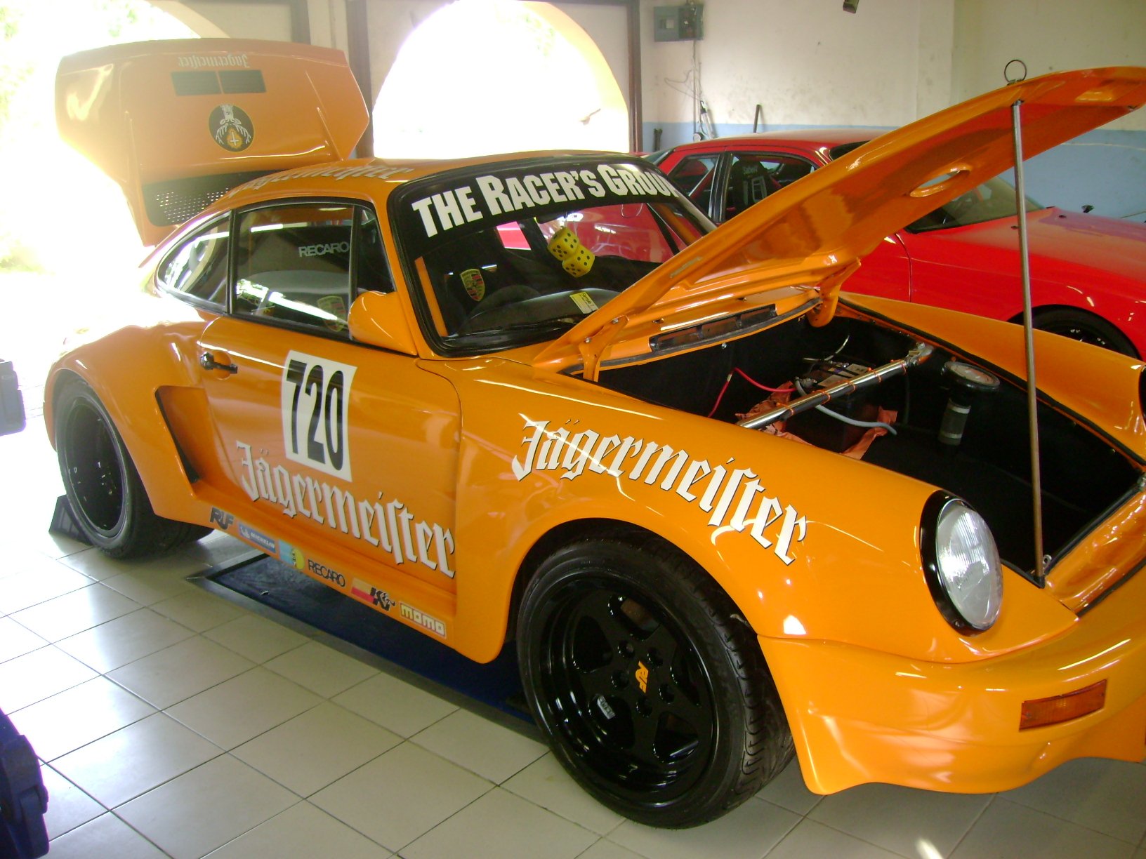
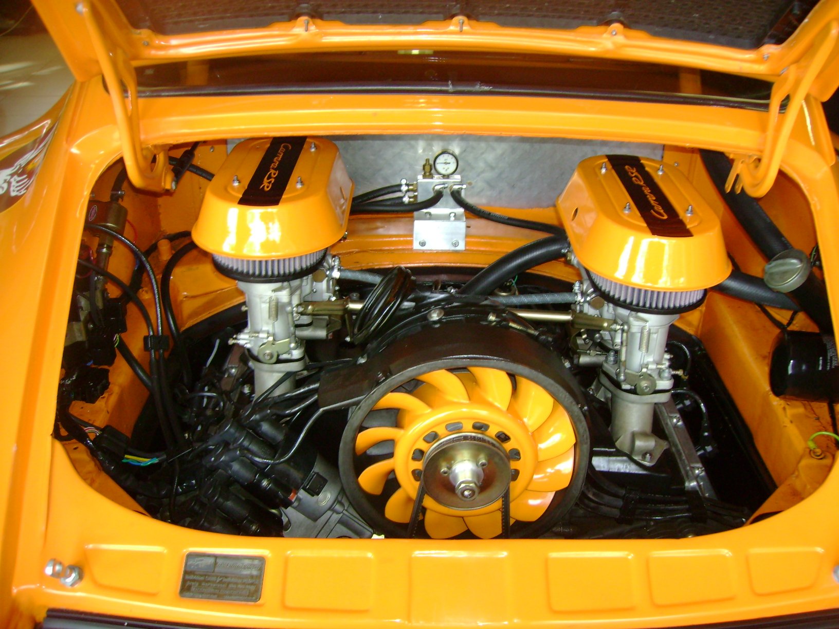
Yep, the attention to detail on the car is something to behold. Engine wise the bottom end is a stock twin sparked 3.6 litre, but the original Porsche fuel injection has been replaced with a set of PMO carbs.
-
Yep, hard to loose money on them Dave. My good lady had a racing accident with her SC and we ended up doing a 964RS body conversion on it while we were fixing it (there is a build thread on here somewhere). We thought we would lose money on that car when we sold it but even with the cost of all of the modifications on top of the repairs we ended up breaking even. I lost a bit on the 993 and even more on the GT3, but that was due to me only owning both cars for a very short time. They were both company cars, so with the tax breaks it made no difference to me, but still. In contrast we doubled our money on the 964 in just under 4 years of ownership. Timing is the key I guess. I did some club racing with a guy who had fitted Toyota throttle bodies with an aftermarket management system on his SC and he was getting substantial horsepower gains with that and custom fabricated headers, so I think you are on the right track with that. Another mate had a twin turbo'ed SC and it was an absolute beast. The chain tensioner upgrade is an easy DIY job and well worth it from a peace of mind perspective. The original tensioners are spring loaded, so tend to go bad over time but you do get an audible warning well in advance of anything catastrophic occuring. Pelican Parts in the USA (if you haven't discovered them yet) are a good source for parts. Thought I'd inspire you by sharing a few photos of my mates RSR inspired wide body SC that was fitted with a 964 engine.
-
Nice porker Dave. You are in for bucket loads of fun. They are simple to work on and parts are plentiful. I owned, daily drove and raced a 82 SC narrow body for just over 17 years. I bought it in 1999 with 119,000 km on the clock and sold it in 2016 with 376,000 km on the clock. The engine was untouched up to 370,000 km with the only work done on it apart from servicing being a new alternator, two clutch replacements and a timing chain tensioner upgrade to the newer Carrera hydraulic tensioners. I foolishly replaced the engine with a newer 3.2 litre Carrera engine complete with the Motronic fuel injection. There is a whole story behind the engine swap that I won't bore you with. The 3.2 was a great engine, but it hurt the resale value being a non numbers matching car. Not that I was too worried about that as the SC had quadrupled in value during my ownership. Was one of the best cars I have ever owned. Funnily enough we ended up buying a second 82 SC for my missus and the VIN numbers on the two cars were exactly 300 units apart. While I still owned the SC and business was booming I moved on to a 993 Carrera 2 and about 6 months later a GT3 MK1, but I had both for less than a year and sold them to go back to the SC as my daily. You just can't beat the raw feeling of the older generation Porsches. My missus moved from her SC into a 964 Carrera 2 and that was a really nice car. Just enough rawness left with a lot more grunt than the SC. If I had my Porsche time over I should have purchased the 993 RS that I was offered when I was looking for a GT3. One of life's little regrets I guess. I sure hope its not a back wheel bearing that you need to replace. It's an absolute bitch of a job. I replaced back wheel bearings twice on my SC. The second time I removed the back banana arms to press in the single piece sealed rear bearings and it was much easier than trying to do it insitu. Bit of useless information for you. The offset pedals is only on the RHD cars. LHD cars don't suffer the same quirk. Probably the result of trying to make a factory designed LHD into a RHD.
-
Yep, agree. My temporary sealed beams look much better but the light they produce is pretty poor by modern standards. I've got a set of semi sealed units on their way and have taken @Raizer's advice and ordered a set of Narva H4 LED bulbs. Can't wait to get them fitted.
-
Thanks for the feedback @Raizer. Am I correct in assuming I shouldn't have to fit relays to run the h4 LEDs ?
-
Pinched the sealed beams off the Thames van for a quick test fit. Looks much better in my opinion than the flat lens modern LED lights that it came with. Now that I know that the mounts haven't been butchered I'll order some semi sealed units as a permanent replacement. I see you can now get LED globes in H4 format. Anyone had any experience with these ? Before and after shots:
- 198 replies
-
- 33
-
-
-
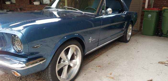
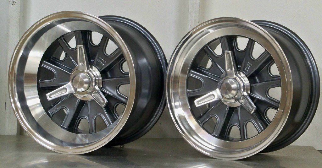
Thanks @NominalYep, totally agree. Spoils the classic look in my opinion. I've been looking for something a little bit different to the usual Magnums or Scott Drake chromed steels. I worry about the quality of modern chrome from a longevity point of view. Would prefer something in alloy with a lip that I can buff up every now and again. I'm currently leaning towards going with these in 15 x 8 with period looking BFGs in a 60 profile. Total diameter for the proposed wheel / tyre combo comes in 10mm more than the current wheels, so pretty close.
-
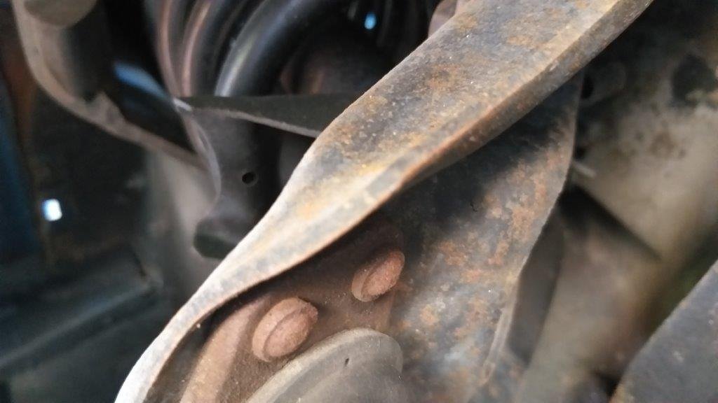
Spent a bit of quality time on the Mustang yesterday. Was my first opportunity to give the underside a good going over. Got to say I'm pleasantly surprised with how solid it is underneath. First step was to remove the modern wheels to check offsets. It's currently running 8J x 18 wheels front and back, both with zero offset. These fit comfortably under the guards with no signs of rubbing so I'm assuming I should be able to replace these with a set of 15s in similar widths with no issues. While I had the wheels off I took the opportunity to poke around underneath. Rear shocks and shackles have been recently replaced so that's good. Looking at the front suspension I was amazed to see that it is still running the factory original riveted in upper ball joints. The rubber boots are well shagged but the joints themselves still feel nice and tight. The boots on the outer tie rod ends are also shagged so I'll add those to my shopping list. The front shocks also appear to be a recent replacement and someone has definitely been at the wheel bearings recently. They look a bit too dry to me so I might just repack them.
- 198 replies
-
- 19
-
-
Yep discs up front. The power steer is surprisingly good although I've heard mixed reports on them. The a/c compressor and condenser came with some other spares in the boot so that's the first thing that needs sorting as it gets pretty toasty here in Queensland. Its not the original piston based compressor so looks like it has had an upgrade somewhere along the line, but time will tell on whether the compressor is still any good. The other interesting thing that it still has is the original C4 "green dot" transmission which I thought would have been long gone by now. Previous owner was kind enough to include the original distributor, 2 barrel inlet manifold, carby and factory air cleaner. Not that I'll ever fit them, but it's nice to have the original bits and pieces.
-
Thanks for the feedback fellas. I really appreciate your comments. I was offered a mint 6 pack blue on blue about 6 weeks back and was really tempted but it was only $7K less than what I ended up paying for this 289, so I'm glad I waited. And thanks Clint for setting up a discussion thread for me. It's been a while since I did one and I was wracking my brain last night trying to remember how I did the last one, so thanks heaps for helping me out. We took the Tang for a quick drive along the beachfront this morning and I just can't wipe the smile off my face. Definitely good bang for buck to be found in these. I've been watching the Mustang market from afar for almost 5 years now and in typical OCD fashion I've been keeping a spreadsheet listing all "near factory" ones that have come up for sale. Looking back through my records it seems to me like they are one of the few cars that hasn't been hit too harshly with Covid tax. The price of classic Holdens and Chevys has just gone crazy of late here in Straya. I've got a lot to learn about Mustangs so its good to know that I have a support network on oldschool that I can ask for assistance from.
-
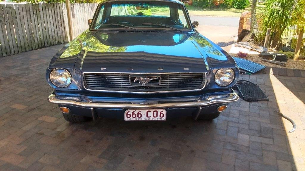
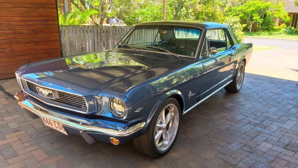
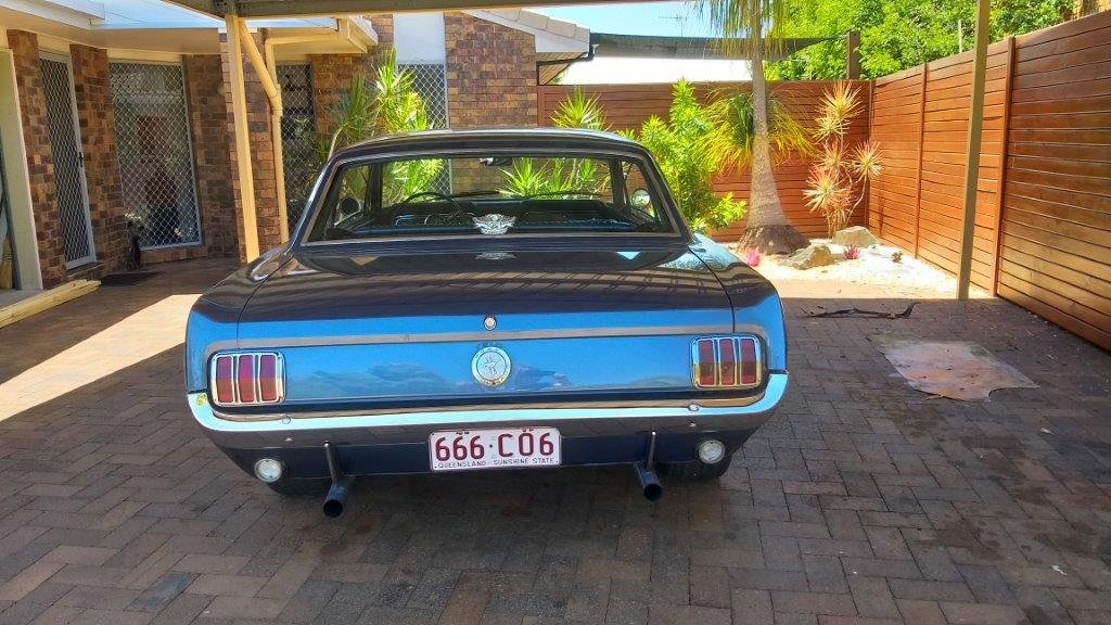
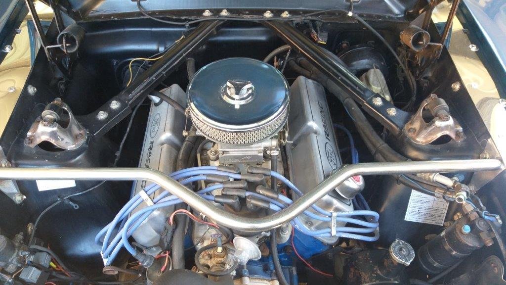
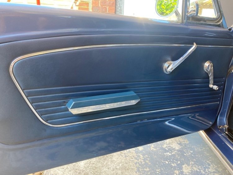
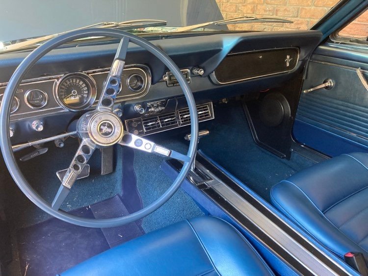
Anyone who has attended a car show or coffee run will have come across them. I’m talking about the 3 or 4 crusty old farts collectively referred to as Team Grumpy. They are usually grouped around a mid – last century American car, scowling at everyone who passes by and moaning about life in general and particularly the youth of today. I’ve always had a quite chuckle to myself as I’ve passed them. Well, life has now come around full circle and has bitten me well and truly on the arse as I officially joined their ranks today. Let me introduce Flash’s latest acquisition, a 1966 Ford Mustang Coupe. But before I delve into the detail, on our latest acquisition allow me to take a few steps back. For a few years now I’ve wanted to add a two door coupe to our small collection of vehicles. I was originally leaning towards something either Japanese or British with an early 70s Toyota Celica, Corolla or Datsun coupe or a Ford Capri topping the list. Unfortunately there is a lot of crap out there with relatively original and unmolested examples commanding asking prices well beyond my budget. They are also a bit of a niche market which makes it easy to over capitalise and if you have dropped some serious coin on one, they can be hard to offload when it comes time to sell them on. Sourcing reasonably priced replacement body, interior and trim parts is also becoming harder for some of these models. I’d almost given up hope of finding anything suitable and then one day I came across a listing for a mid 60s Mustang coupe. I’d always shunned these cars, particularly due to their association with Team Grumpy, but something about this listing just rang a bell for me. After all it is the Mustang that was the original inspiration for a lot of the coupes that were on my short list, so I started to delve a bit deeper into the subject. A bit more investigation revealed that the Mustang market is a pretty stable one with a steady demand for near original unmolested examples, parts are relatively cheap and readily available and they have some classic lines. And so the hunt began. I’d set my sights on a 65 or 66 Blue on blue version. Why this particular model ? Well I find the dashboard and in particular the 5 gauge instrument cluster of the 65/66 to be the most appealing. Why blue on blue ? Well I previously owned and daily drove a 1982 blue on blue 911 SC coupe for almost 17 years and I absolutely loved the colour combination. Anyway, now on to this particular car. Born in April 1966 this car has spent the best part of its life in San Jose California. Nine years ago it was purchased from its second owner by an Aussie visiting the USA who ended up shipping the car back to Australia at the end of his holiday. After arriving down under it quickly passed on to its 4th owner who owned it for 7 years. The sudden arrival of twin boys has increased his brood to four with the result that the family can no longer enjoy runs in the Mustang and custodianship has now moved across to me. It is one of many that I have looked at over the past year or two, but there is something about the honesty of this particular car that appealed to me. It is by no means a show pony showing a few scrapes and dings, but the interior is immaculate and the engine bay presents very well. I’m not a fan of the modern 17 inch diameter wheels and the LED headlight conversion gives me the shivers, but they are modifications that are easily reversible. The paint is not factory but it is over 10 years old so I figured “what you see is what you get”. There are a few rust bubbles in both doors and the gaps are not that good, but apart from that the car is solid. Well enough bloody chit chat Flash….. let’s see some bloody photos mate.
- 198 replies
-
- 37
-


.jpg.f0f86fbfcee56c0ec0e5221b8366c29e.jpg)
.jpg.9592ef5365f7e3fdba33b454b2f72b95.jpg)
.jpg.3e1564d793b1d29db595b6bb4360df56.jpg)
.jpg.f41d09fd0545a03202c2792643b65f5e.jpg)
.jpg.342a3429cd53a250e8a21f3395fdc95f.jpg)
.jpg.15bbf155f2edc9c32855f49fdf1ee23a.jpg)