Adoom
-
Posts
2,279 -
Joined
-
Last visited
Content Type
Forums
Downloads
Events
Gallery
Everything posted by Adoom
-
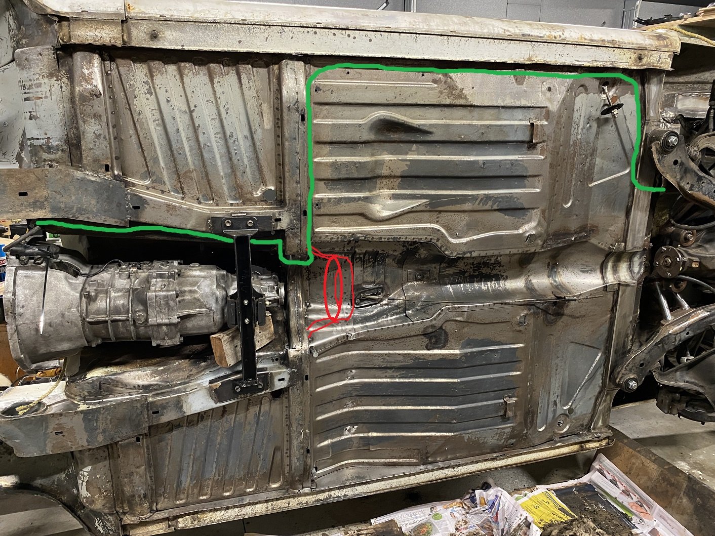
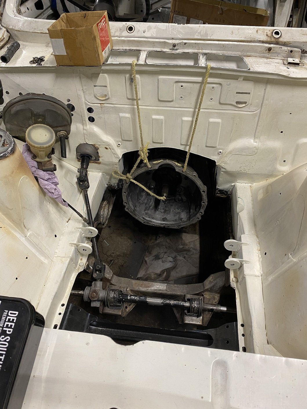
Cool, I'll run them down the side. The driveshaft hoop will be something like the red scribble. The sides of the tunnel and front seat area has two 'floors' with a cavity for some reason so I was planning on bringing the hoop mounts forward to the chassis box section.

-
Do I recall something about proximity of things like fuel line, battery cable and brake line to the propshaft when routing under the car? Or does it not matter where I run them as long as it's secure, not going to hit the ground and can't touch things that move or spin?
-
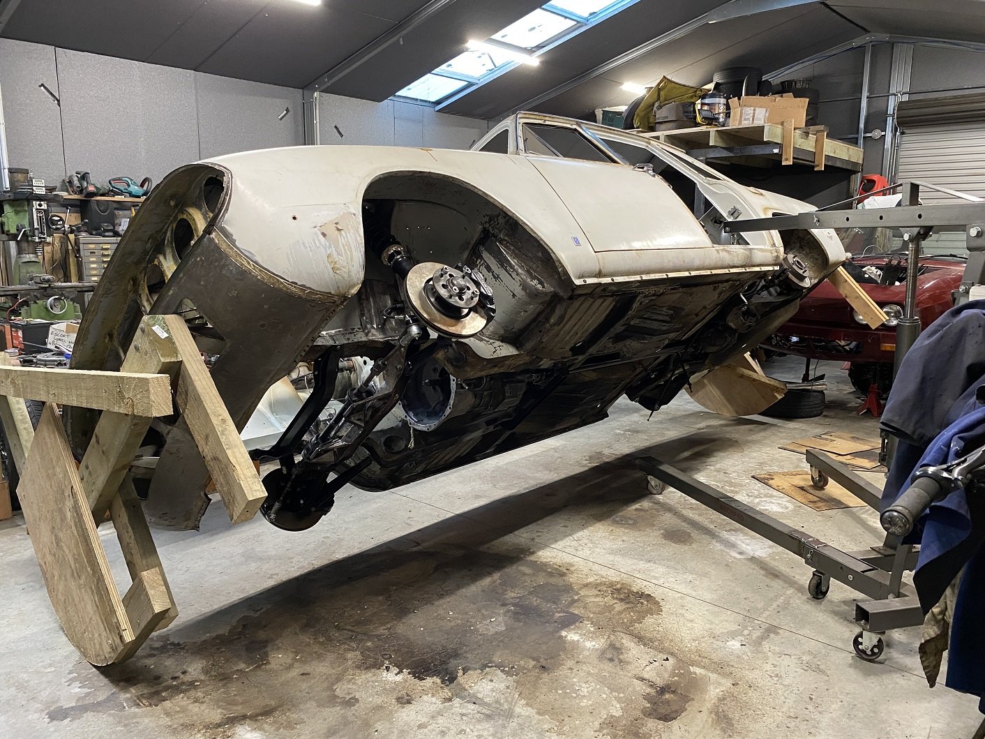
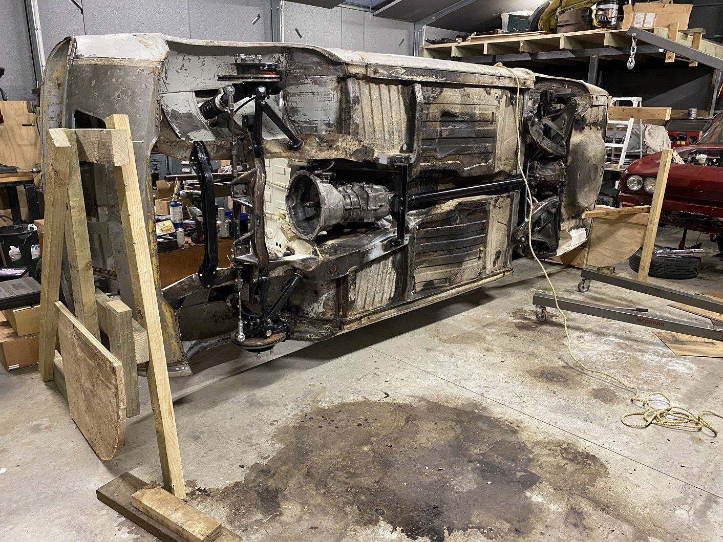
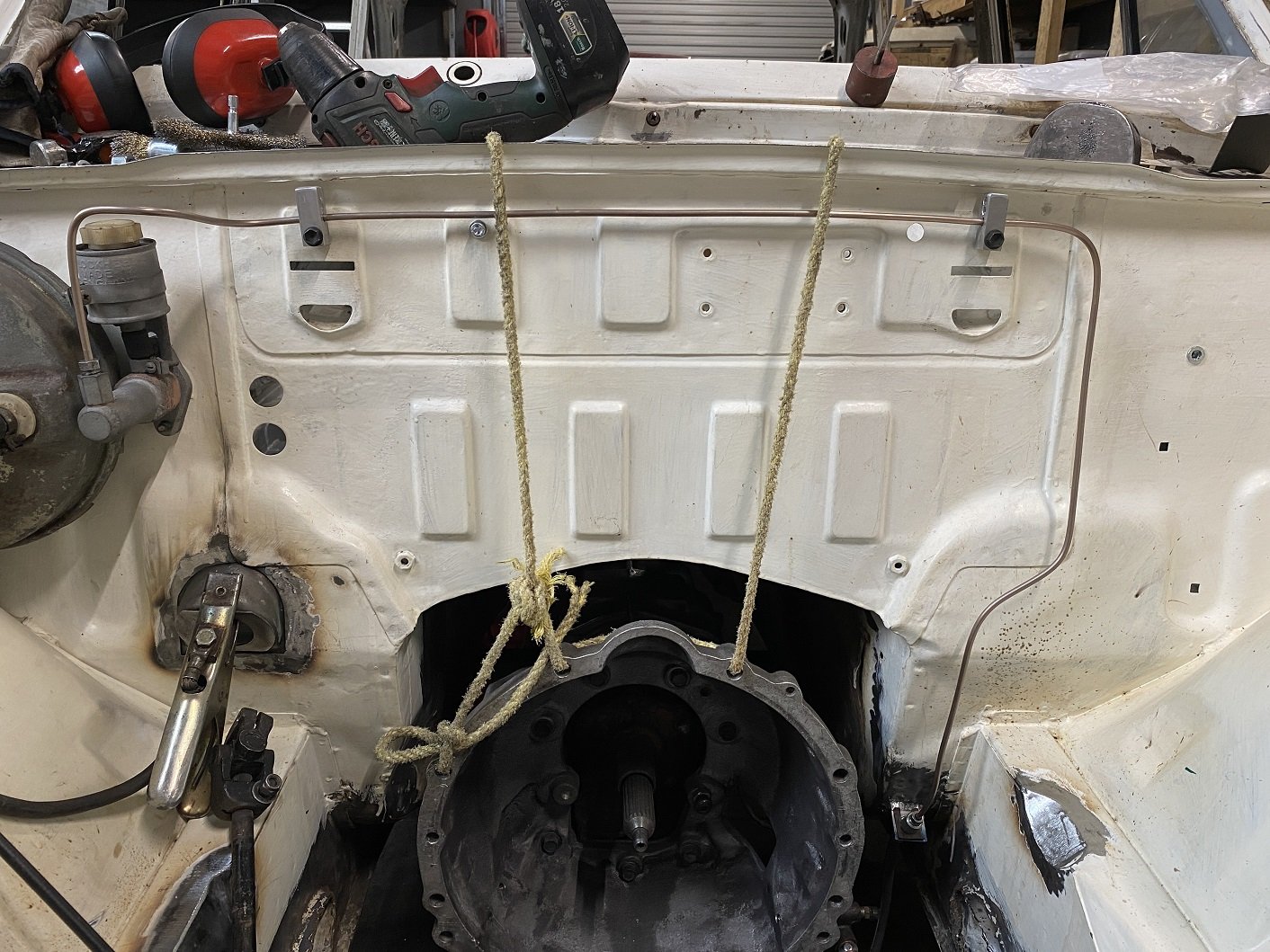
This make some things easier.... I bolted the don't-fall-on-me props on so they can't accidentally be knocked out. It's a bit bottom heavy with all the suspension still attached so it does want to come back down.
- 201 replies
-
- 26
-

-

-
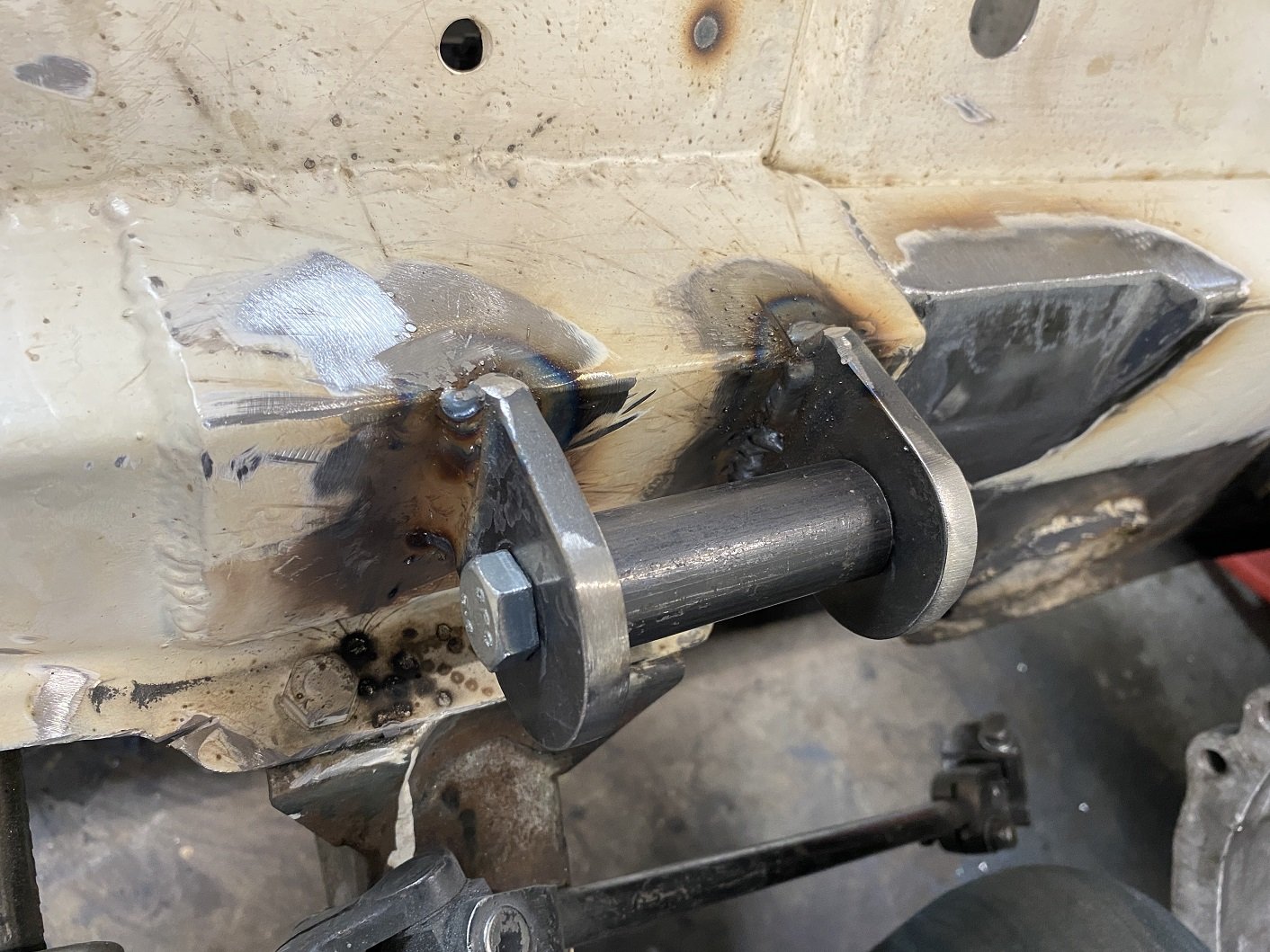
Engine mounts redone in thicker material as advised by the man. 8mm should do it. I machined up a spacer and did half at a time so I could use the original half to keep the alignment. But I also added a 4mm spacer when welding on the first new half to shift the engine back a tiny bit and give me just a little more clearance between the cross member and the sump. I hope that doesn't come back to bit me in the arse later. When welding in the second half of each mount I replaced the 4mm spacer with a fibre washer as a shim so it's not such an uber tight fit to get the bush/sleeve in there.
- 201 replies
-
- 23
-
-
The stuff I have on my shelf is Duplicolor. I'll try some VHT. Thanks.
-
Discovered that the caliper paint I've used is rubbish. Blasted half off half of it with compressed air. They are aluminium so won't rust. Does anyone recommend something that actually sticks and comes in a spray can?
-
Is the bar trying to occupy the same space as the intercooler? Tetris harder.... Or was it just blocking airflow? I'd just let it block that top section of the intercooler, it will probably still do some cooling in that section.
-
I'm running them high because the there is very little space between the engine and firewall. I came across a Staaaaaaaag brake diagram on Rimmer Bros which looks identical to the 2500 tandem system. The same master cylinder is listed for both cars. Front port goes to the rear brakes. I'm going to have separate short sections of pipe going to the master cylinder, so if It's wrong, I only need to remake those short bits.
-
Could anyone else with a Triumph that has a tandem brake master cylinder check which ports are for the front/rear please. AFAIK, both lines go to a 5 port pressure imbalance switch thing on the passenger side. Then one comes back for the FR brake, one goes to the FL and another goes to the rear. I've looked in the two workshop manuals and factory blue manual I have but they only show the routing for the earlier single circuit system.
-
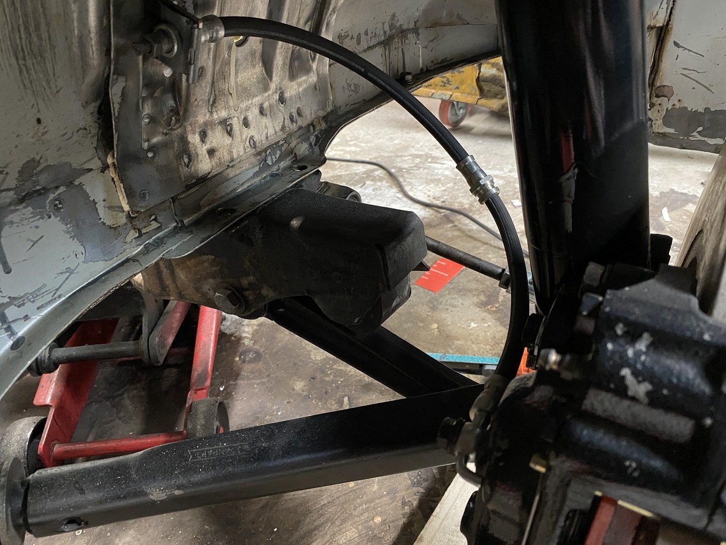
A clutch line. Bent by hand so not robot straight. I made it a little longer than required just in case I need to redo the flares. Hopefully having it go higher than the reservoir do not cause issues bleeding. The reservoir is just on a hose and bracket, so I could make it higher if I needed to. And the hose bracket I made. With the hose like this it keeps out of the way of the wheel and it doesn't get tight from lock to lock. The hardline originally went under the chassis rail, but it will be way too close to the exhaust, I'll run it through the inner wing.
- 201 replies
-
- 17
-
-
Thanks! Yours look way more refined than my blocks. But they look like they will be too big for me to use. I can make more blocky ones if needed on my manual mill. I might even think about rounding the corners or using the DRO for the spacing instead of "looks about right"...
-
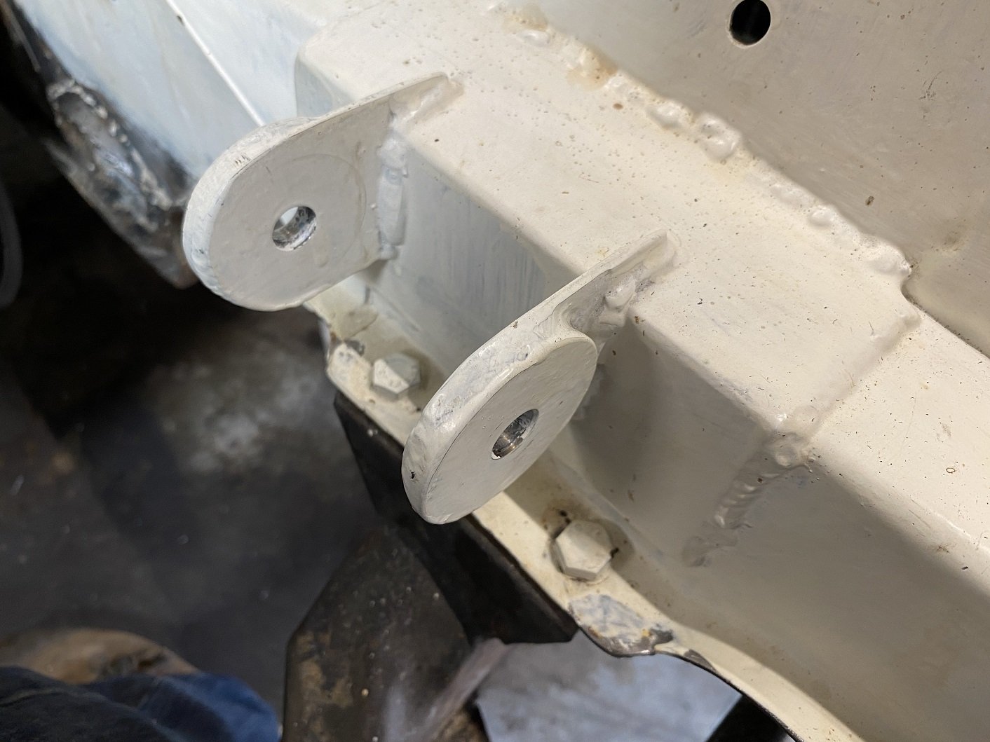
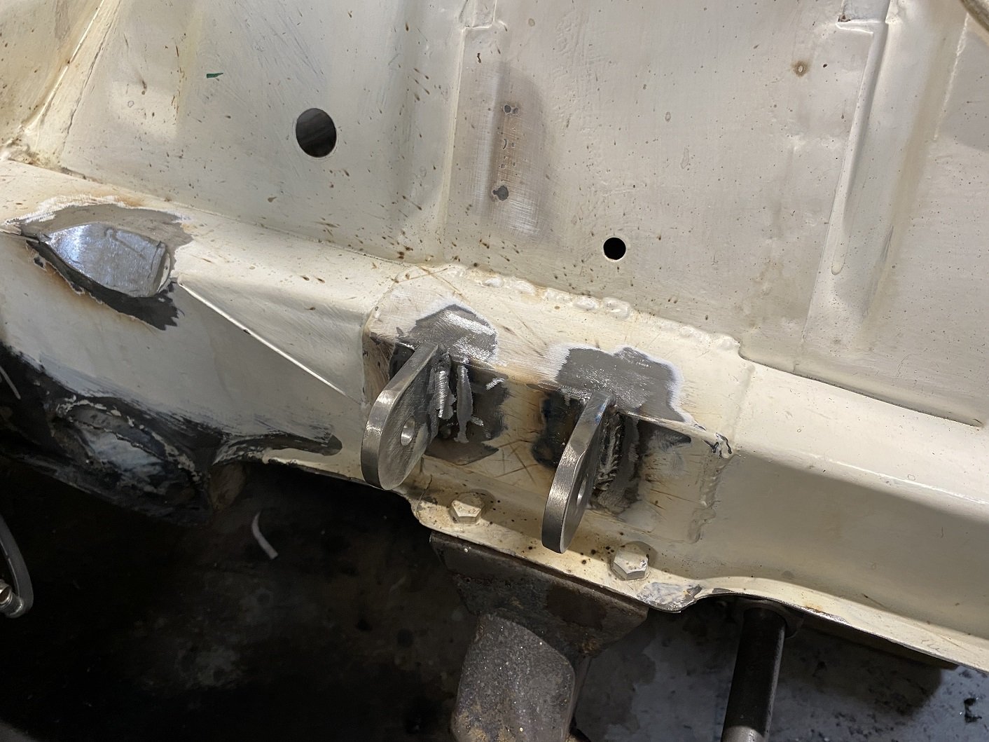
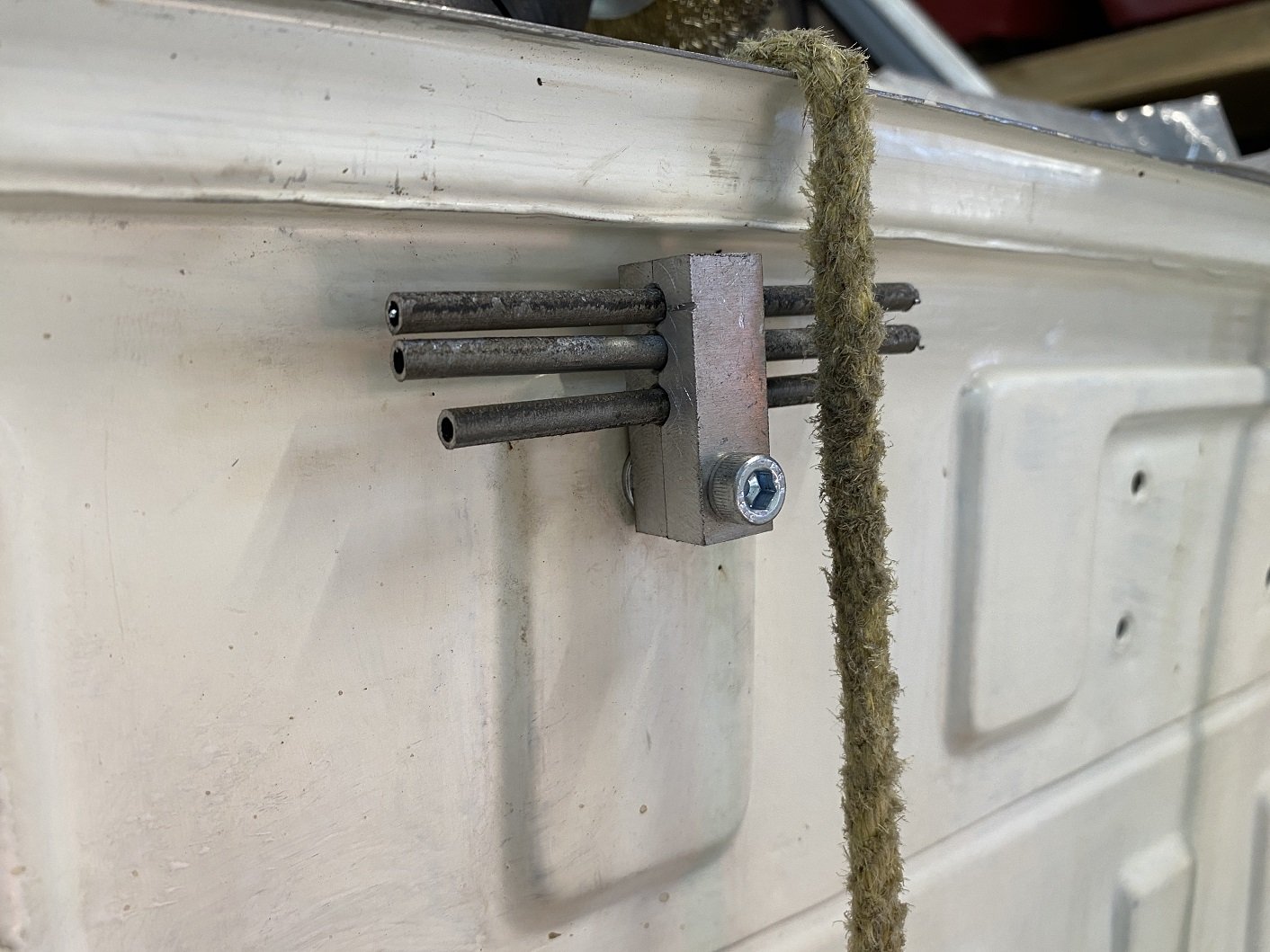
Could not find anything for three lines that was available... Left front caliper, clutch, line to rear. So... yeh? Or nah? They are a loose fit. 5mm drill for 3/16th pipe(4.6mm?)
-
Been working on the clutch plumbing. And welded in the lower steering column mount. And made the reliefs in the chassis rail for exhaust and steering shaft. I need to find/make some bracket type thing to hold three 3/16th brake pipes that need to run across the top of the firewall. As close together as possible...
- 201 replies
-
- 13
-
-
I too can hook you up with a round thing with a hole in it.
-
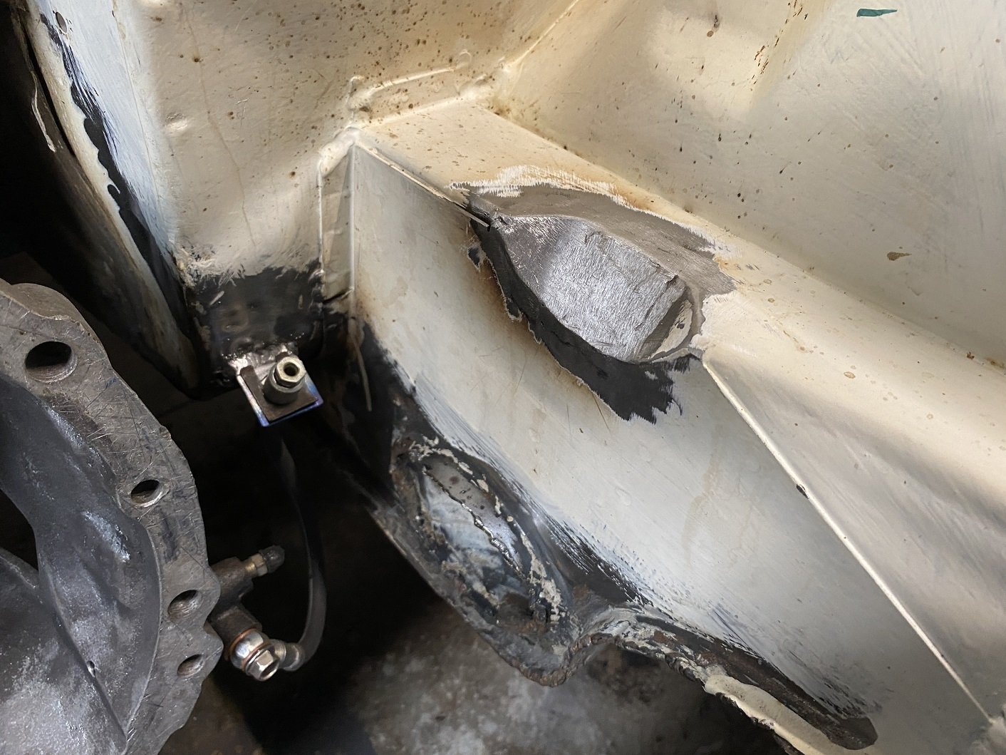
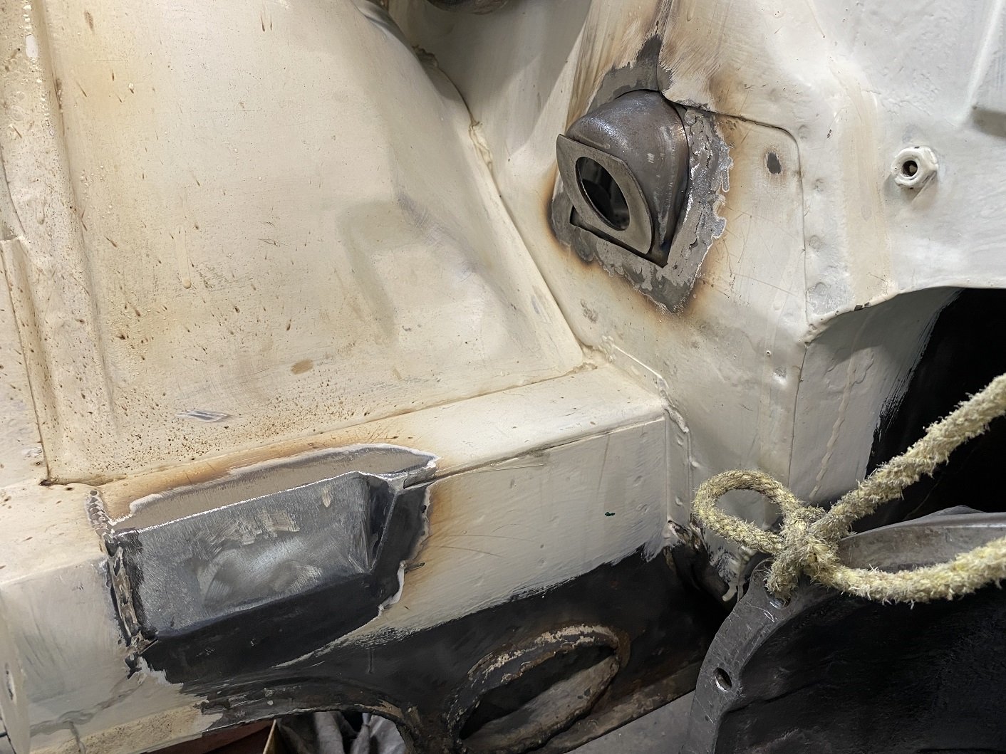
Scooped the engine back out the hole. Then put the gearbox back in so I can do the clutch and brake lines. I'll also be redoing the engine mounts as cert man wanted them thicker. And I can weld in the relocated steering column lower mount. I'll also be clearancing the chassis rails a bit more for the passenger side exhaust cause I put it in the wrong place the first time. And some clearance for the steering intermediate shaft. Epotec goes a bit toasted marshmallow if you use a MAP gas torch to soften underseal for scraping it off...
- 201 replies
-
- 14
-
-

Discuss here about Yoeddynz's little Imp project...
Adoom replied to yoeddynz's topic in Project Discussion
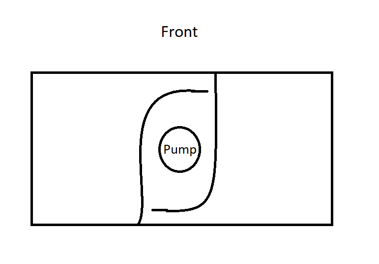
Can you draw a diagram showing how the K11 surge tank pump box thing works? I need to make a custom tank for my Triumph, to fit between the strut towers it has now. I'll need to figure out some kind of arrangement to prevent surge. I was thinking of putting in curved partitions so the fuel gets trapped in the 'dam' rather than going all the way to the end of the tank. I don't really have the space to make a well in the bottom.
-
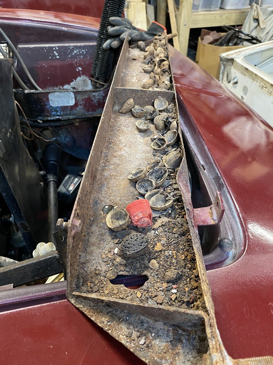
There is a bolt together structure forward of the chassis rails to support the 'nose' of the body and provide mounting points for the bumper. It had some damage from a front end impact. I dunno if that predates @dmulally 's ownership. Some of the structure was bent and rusty. The loom was also earthed on part of it, but that part didn't seem to be bolted to anything and just floating. I decided to take it out. WELL... I guess some rats were using this as a dining room for a while... Some of the fibreglass was also damaged and sorry if it was you Damo, but OMG it was not patched together very well and is failing. Who ever laid the glass mat probably also scrunches toilet paper rather than folding. There's delamination and big flappy bits of mat sticking up all over the show. I assume it was done by feel, upside down, because of poor access. I think I'll cut/grind/sand it out and have a go myself.
- 6 replies
-
- 17
-

-
-
I had planned to have to weld in the front portion of the yellow guard because I deemed the panel damage beyond my skill to repair. The step thing on the corner had been totally flattened by someone else's previous attempt. I had a go at it myself maybe a year or so ago. But then the other day, I thought I'd have one more go, if I fucked it up I could still weld in the other panel. So I just hit it much harder... I think it's acceptable now, I reshaped the step and didn't fuck up the two... ridge line things. Should only need minimal filler. I also trimmed the doner front panels so I could trial fit them. This car had run into something and pushed in the front panels, folding over the lower front seam. I was unable to get the panels the budge with a slide hammer, so I decided I'd use the front panels from the yellow one, which were surprisingly rust free, unlike the rest of the yellow car. Front panels look like there will be no issues fitting them. I'm not ready to weld the panel back in, I still need to prep behind it for epoxy.
- 201 replies
-
- 25
-
-
I've got a 3-piece wheel that's got a tiny leak where the halves join. If I use the soapy water on it, it slowly makes foam. The bolts are real tight, I suspect they have never been removed. So I guess the bead of sealant around the join has a hole somewhere. The plan is to clean it real good and see if I can find the hole using compressed air from the outside... But I guess I'm just going to scrape most of the sealant out and run a new bead. But what sealant do I use? Is it the same stuff as roof/gutter sealant, or the stuff for the shower????
-
Did you use any stain remover, or just normal washing machine stuff? I've used SARD and it does a pretty good job getting a bunch of the oil out of my overalls. Just got to pick all the nuts, bolts and swarf out of the machine afterwards.
-
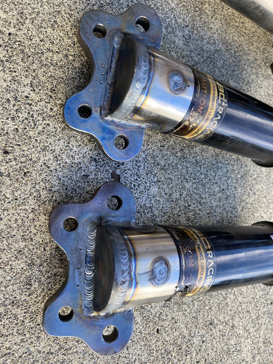
Albert the NDT man in Wingate has tested the welded struts for cracks. Took 10 minutes. He has an electromagnet and a solvent containing iron particles dyed with a flourescent dye so they glow in a UV light. He puts the magnet across the weld and sprays it with the fluid. The magnetic field aligns the iron particles which you can see under a UV lamp because of the dye. Any cracks will cause misalignment because the field goes around them. So I've got a certificate that says it's passed. YAY!
- 201 replies
-
- 22
-
-
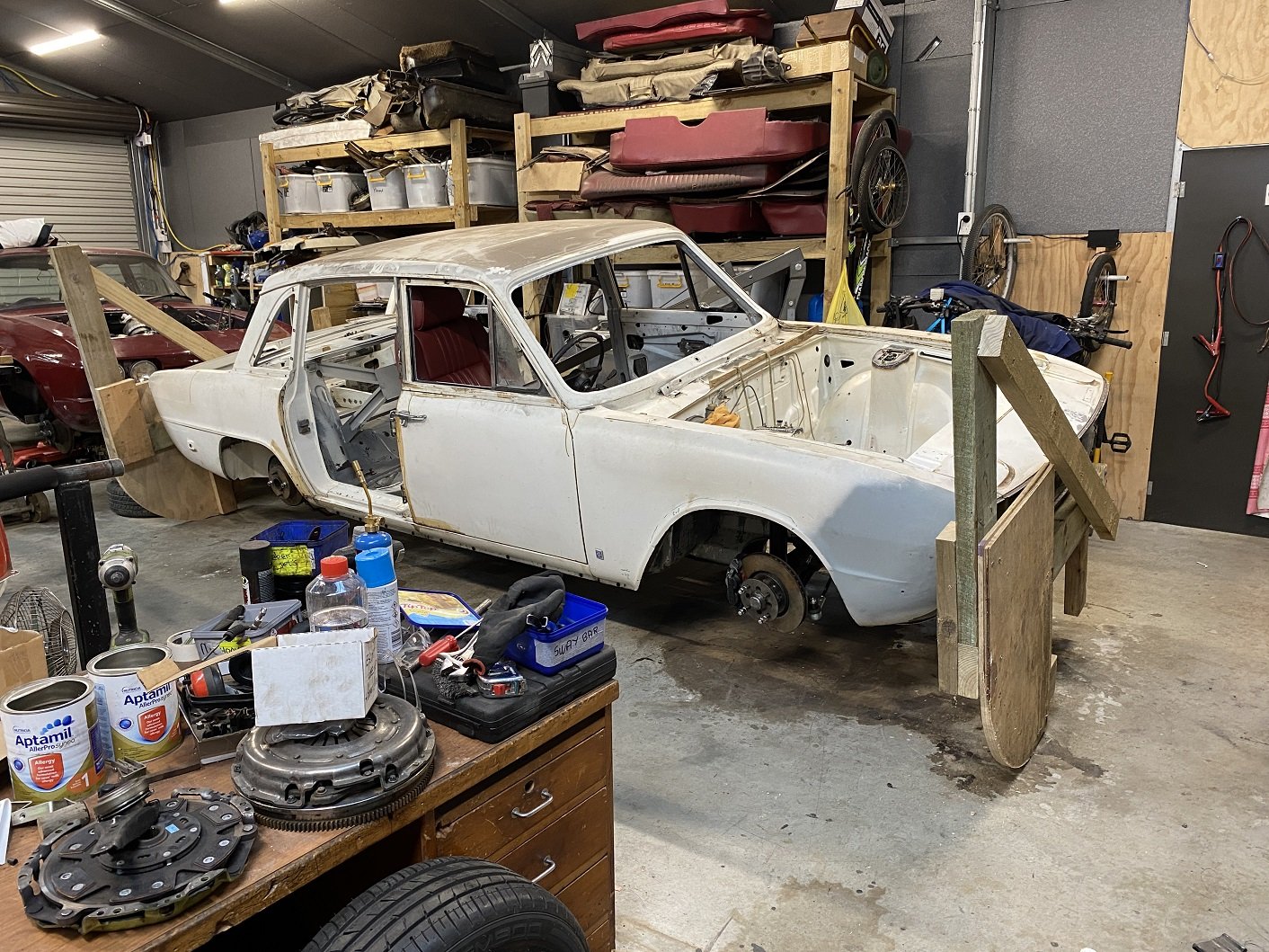
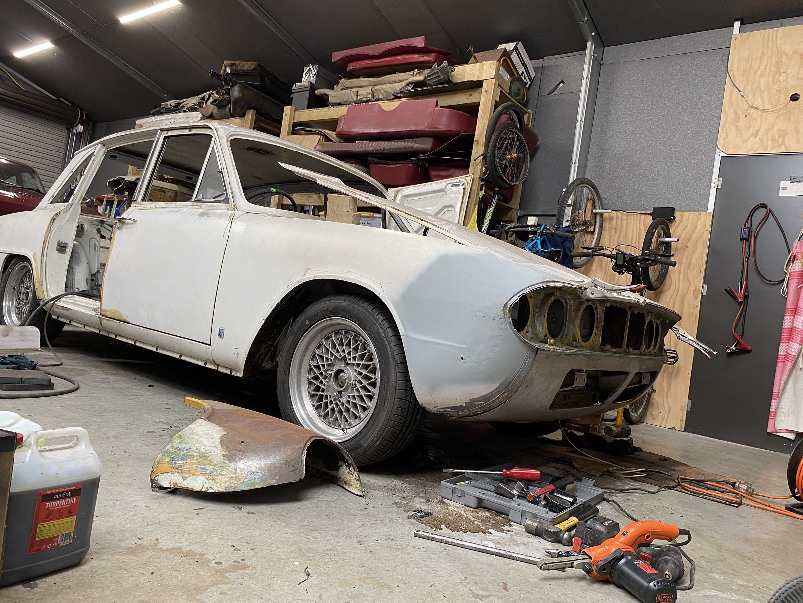
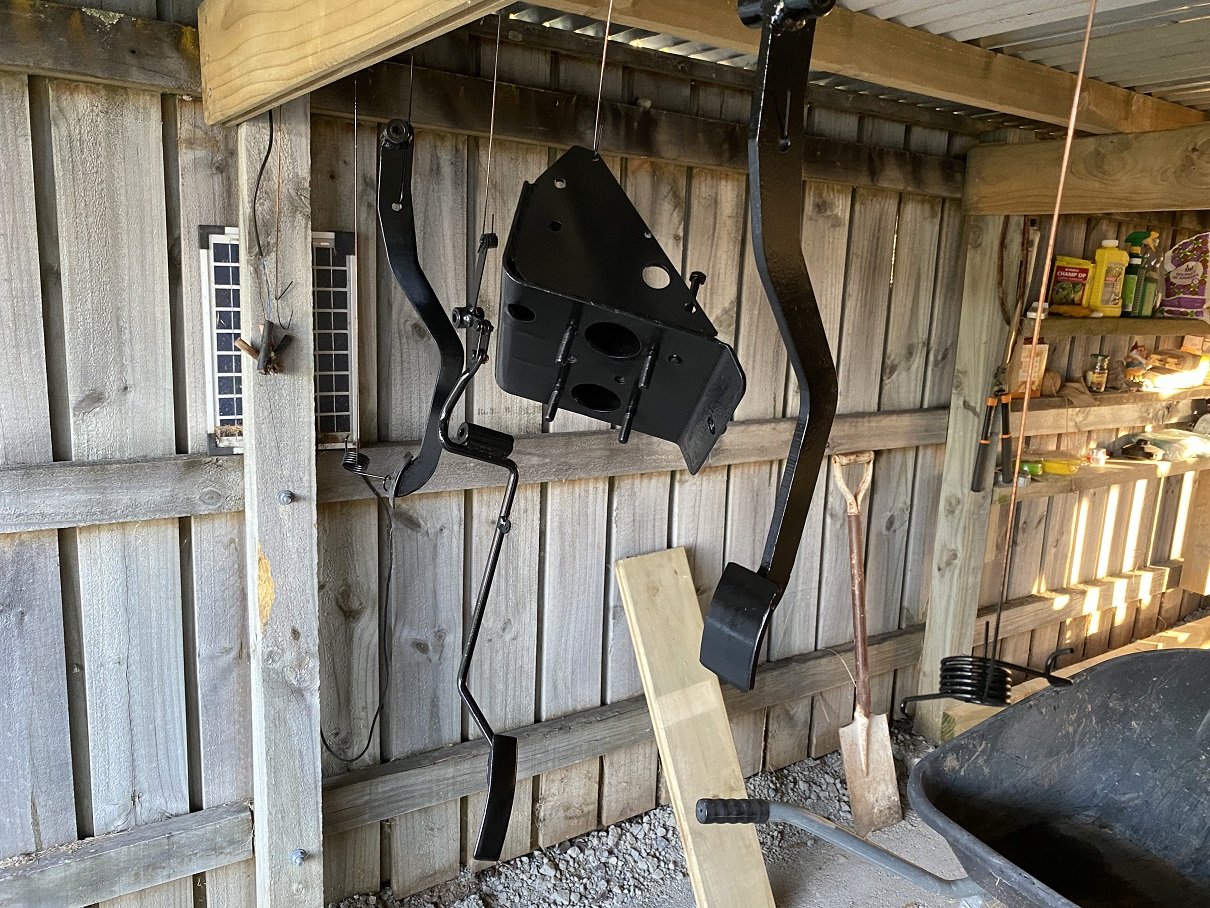
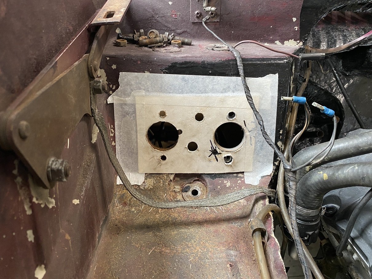
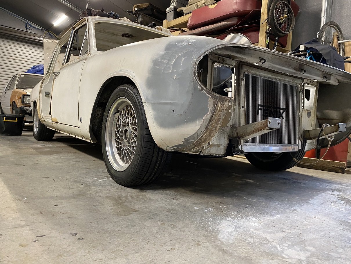
The Scimitar has swapped places with the Starlet into the garage because I wanted to roll around underneath and gravel floor makes that suck. The chassis looks good, couldn't find anything but minor surface rust. YAY! The car is an auto but a manual pedal box came with it. It was gross, so I stripped off the hideous green paint and rust in the sand blaster. Also tried one of the smaller nozzles on the gun. 300% more effective! Wish I'd thought of it ages ago. Paint it black. Made a template from the pedal box for the clutch master cylinder hole. The auto/manual pedal box is basically identical, but on the auto, one of the side plates is not there. The auto one does have the clutch hole too, there's just no studs. Then drilled the extra hole. The fibreglass is about 10mm thick here! I'll epoxy paint the whole area here to amalgamate any worn... fraying fibreglass. I had to remove the remote brake servo to get the drill in. I'm going to assume the remote servo wasn't doing much because the diaphragm part was half full of brake fluid. I sand blasted all the oxidation off the aluminium anyway. AFAIK, the early scimitar used the same size master cylinders for the brake and clutch. So I can probably use the old brake master for the clutch master, assuming it's rebuildable and find an appropriately sized dual circuit brake master(YES, it was SINGLE CIRCUIT BRAKES!) to go in it's place. Possibly using the remote servo on the front circuit(if it can be rebuilt that is).
- 6 replies
-
- 16
-
-
Actually, I take that back, the engine front cover doesn't look right.
-
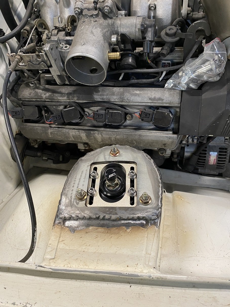
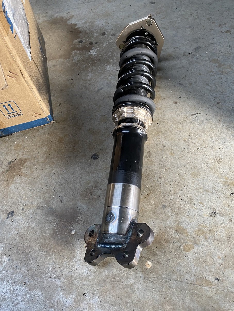
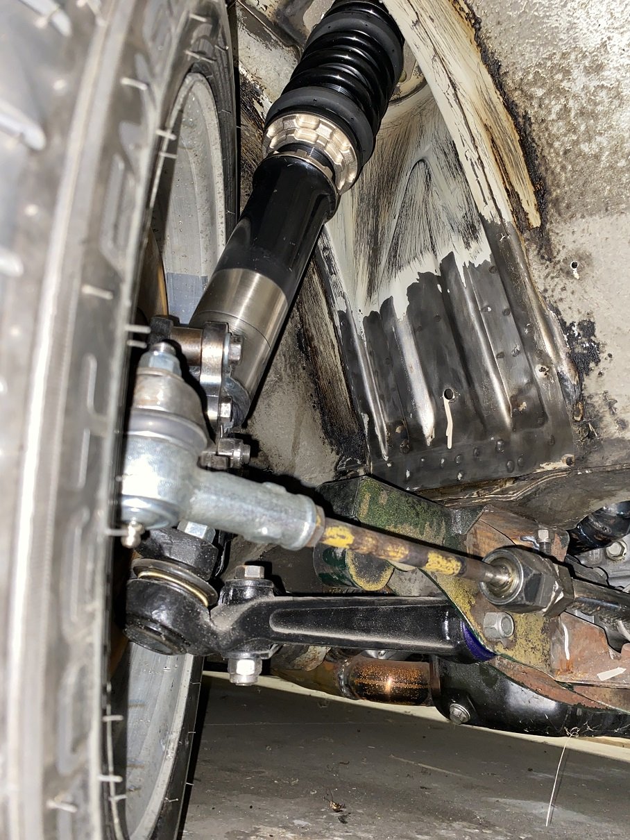
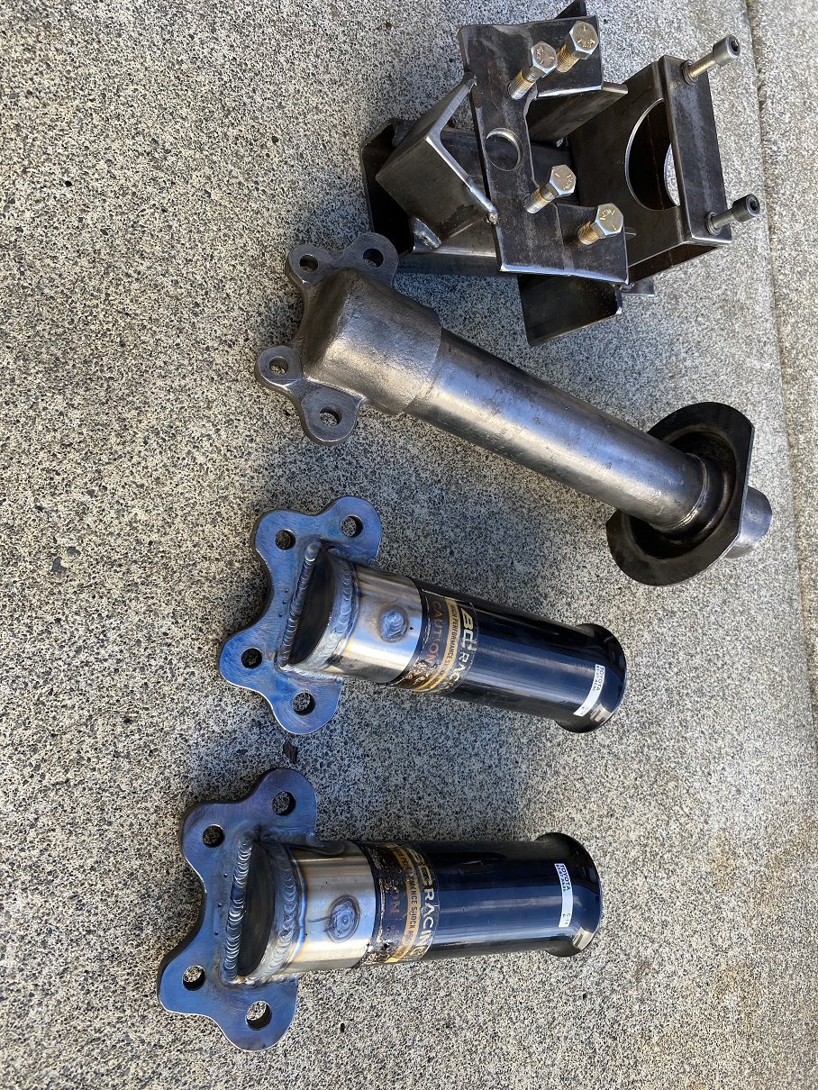
I sent in my design approval forms for the LVVTA Technical Advisory Committee in late Dec. Their next meeting wasn't until Jan. Late Jan. At the end of Jan it was posted back to me and the design was approved. So THE NEXT DAY I went to may certifier's favourite welderm Graeme Kidd in Upper Hutt. A couple of weeks later, he'd done it. AS SOON AS I got in the gate at home. I put them in the lathe and sanded off the burnt sticker and powdercoat. They still need to get NDT tested in Wingate. Graeme says it's a crack test. But I could not wait to try fit them. I had already modified the top plates and the strut towers the previous week. Using a straight edge and the angle thingy in my phone, it's got 0 deg camber at ride height with plenty of adjustment in both directions. They ended up 10mm shorter when installed than I'd calculated. So that's a bonus, the adjustment won't be totally bottomed out at ride height. On it's own wheels and suspension! I can push it around! It's 10mm lower at the front here than the back. I may raise it up that 10mm so there's a bit more travel. The springs are 6kg I think. I was expecting them to be WAY too hard, but If I bounce on the guard it doesn't feel massively stiff. The engine needs to come back out now so I can redo the engine mounts on the chassis in thicker steel like the cert man said. And to weld in the lower steering column mount. I should paint the exhaust manifold while it's out, it's getting surface rust on it. And one of the front split rims has a leak, so the tyre needs to come off to redo the sealant.
- 201 replies
-
- 31
-
-
I believe that may the the same engine series as mine? Any chance of photos of the alternator mounting?