Adoom
-
Posts
2196 -
Joined
-
Last visited
Everything posted by Adoom
-

Random slightly cool stuff you built but not worth its own thread, thread
Adoom replied to h4nd's topic in Other Projects
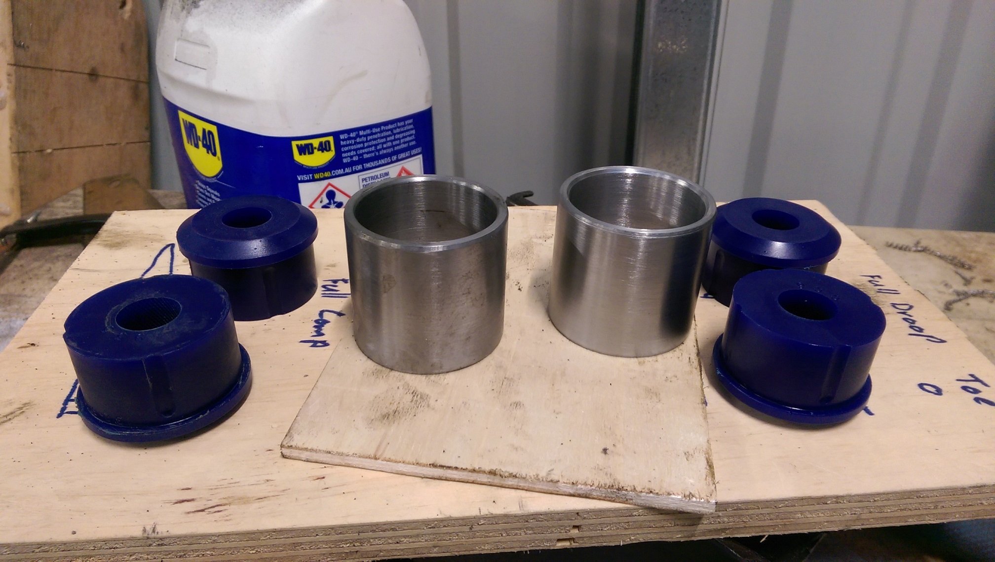
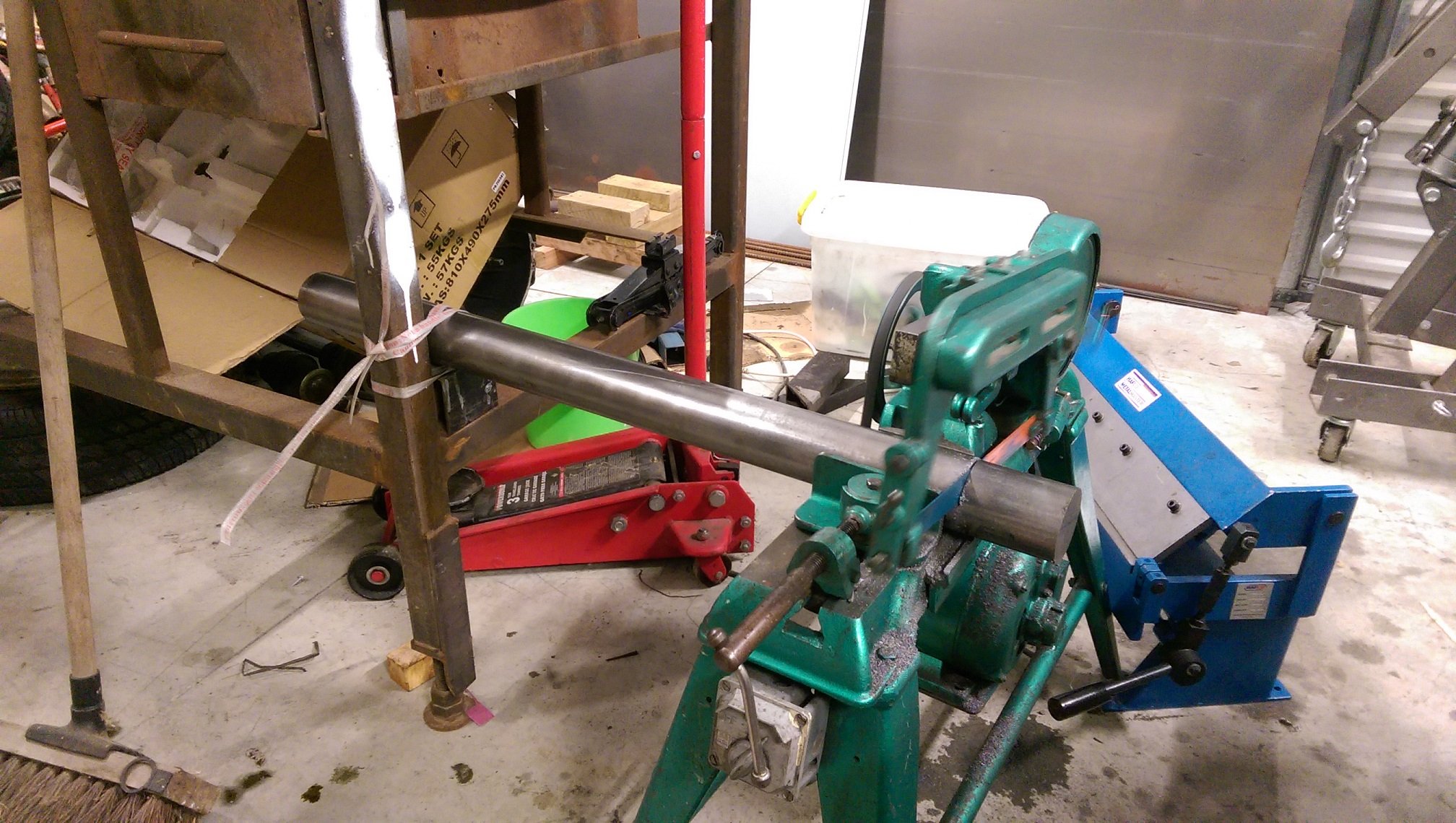
Mental note for next time: Buy bushes that fit a std thick wall tube size! So I bought the bushes because they were close to the dimensions I wanted for engine mounts. But then I could not find any thick wall tube even close to the right size. I can make some. I have a tiny lathe. How hard could it be... #FirstRealThingMadeInLathe The bush diameter is 47mm. The closest size bar stock I could find was 65mm. It took a while to cut through with the power hacksaw. The saw would also walk and the bar fall off the shims fucking up the angle of the cut. I sorted that out! I did the first cut with a blade with quite small teeth and it took fucking AGES! I broke that blade later, so when I cut the next one I used a blade with bigger teeth(it was all I had), it cut quite a bit faster. But it still took a really long time. Then I whittled it down in the lathe. The deepest cut I found I could do was 20thou/0.5mm any deeper and it would jamb and break the carbide insert. ELEVENTY BILLION HOURS later! Actually the first one took 6-7 hours including cutting it off the big bar. The 2nd one I spread over several days. So glad I didn't fuck up the sizes and have to start again. Bushes fit perfectly.
- 1289 replies
-
- 17
-

-

-
It's okay, you can say "4AGE" in here, it's a safe place. 4 cams! Where did you fit those?
-
I'm thinking I will weld the engine mounts to the chassis rails/strut tower in the Triumph 2000. Mainly because there isn't enough realestate available on the cross member. I assume I will need to plate the area I want to weld the mounts to? Yes? How thick should the plating be? is 1.6mm too thin? I'm sure I saw a post somewhere with a mount like this ripped out and Cletus said it should have been stitch welded? But I cannot find the post.
-
If there was not much flow when bleeding the front. I would start at the master cylinder, remove the brake line, for the front system, from the master cylinder and pump the pedal, you should get a lot of fluid. If you do, reattach the line the line to the master cylinder, and disconnect the other end of it from the "splitter", pump the pedal. If you get lots of fluid, move to the next join and so on.
-
I came across a Triumph 2000 and 2.5PI FACTORY service manual on the tard. It's got loads more info and measurements and scale drawings in it than the Haynes/chiltons owners manual. I specifically bought it for the chassis measurements diagram. The one you use to tell if the car is bent/twisted. Never seen that diagram anywhere before. I'd like to scan the whole thing for prosperity but it's a ring binder of hundreds of double sided pages and some are double size fold out pages, so I can't really put it through the auto feed thing on the scanner. And there is some old sticky masking tape reinforcing some of the punched holes, so it probably won't survive going through the auto feed rollers. Long story short, I'll have to scan each page manually and it will take hours and hours.
-
Where are you looking/reading? I've just gone through the car construction manual and the only "clearance" reference I could find related to my situation is the 25mm+ clearance required between steel universals and the exhaust, before you need to have heat shields.
-
Aye? Where you seeing that? As far as I know, the rack housing can be as close as you want as long as it can't touch/rub.
-
I could. Cheers. I'll have to read through the pdf a few more times to get my head around how my degrees relate to the mm measurements.
-
From factory the rack inner pivot is WAY above the LCA inner pivot. The tie rod end normally mounts on top of the steering arm. With the lowered rack, the rack inner pivot is 10mm below the LCA inner pivot. I've mounted the rod end bearing(replacing the tie rod end) under the steering arm. With the spacers I have now, the two outer pivots are also 10mm apart. I can raise the rack about 7mm before it hits the alloy sump. I'm fairly sure the oil pickup pipe is in the way of cutting the sump. I've got no room left to move the engine up/back. The design of the front hub does not allow for the LCA outer pivot to be lowered. The balljoint taper fits directly into the hub casting. You say "minimise the bump steer". How do I know when it is minimised enough?
-
Nah, it's a dick. All weird and british. The steering arm bolts to the back of the hub. Nothing like a toyota/etc. So it cannot be spaced down. I did think about maybe using a strut/hub from a japanese car, but then I'll probably have camber issues because of the angle of the strut/spindle. And this has the rack in front of the cross member and most jap cars have it behind. Also everything on this is in inches.
-
I suppose I should. But I'm lazy and I'd need to assemble all the suspension/steering/crossmember and fit it to the other(really rusty) shell I have.
-
Not that either. Cross member is in the same place, but the rack is ~50mm lower than factory. So I've also had to lower the tie rod end the same amount, which in theory gets the bump steer back to normal. My imaginary wheel/tyre/distance between the pins is 470mm or 18.5".
-
I'm confused by your question. I've measured the up/down suspension travel in mm. And the angle the wheel is toeing in/out in degrees. Which I calculated using the distance between the two pins and how much gap there is between one of the pins and the board bolted to the wheel hub. (as the wheel turns/steers one of the pins lifts up). mm by themselves are a bit meaningless if you don't know the distance from the wheel center the measurements are taken from. eg: The largest meausrement I got was 5.5mm, but if I measured further away, I'd have a bigger number for the same wheel angle. I had read that pdf you linked. I can't use the method they describe because I've only got suspension(and modified steering) on one side of the car. Nah aye. I've lowered the steering rack, because there is an engine in the way, now I'm trying to fix the bump steer that has caused. I'm not talking about bump steer from lowering the car "too much".
-
So what's "acceptable" bump steer? I made a contraption to measure it. Ignore the g-clamp, the bolt is too short. Over 100mm of travel, full droop to full compression, I'm getting 0.67 degrees of toe change. As the suspension is raised, it toes out. If I run the ride height I'm thinking of running, the travel will be reduced to ~60mm and the toe change would be about 0.45 degrees.
-
Yay, the wheel still fits with the rod end/tie rod flipped upside down and that huge bolt head there. There is even a bunch of space left if it needs to be spaced further down to adjust the bump steer.
-
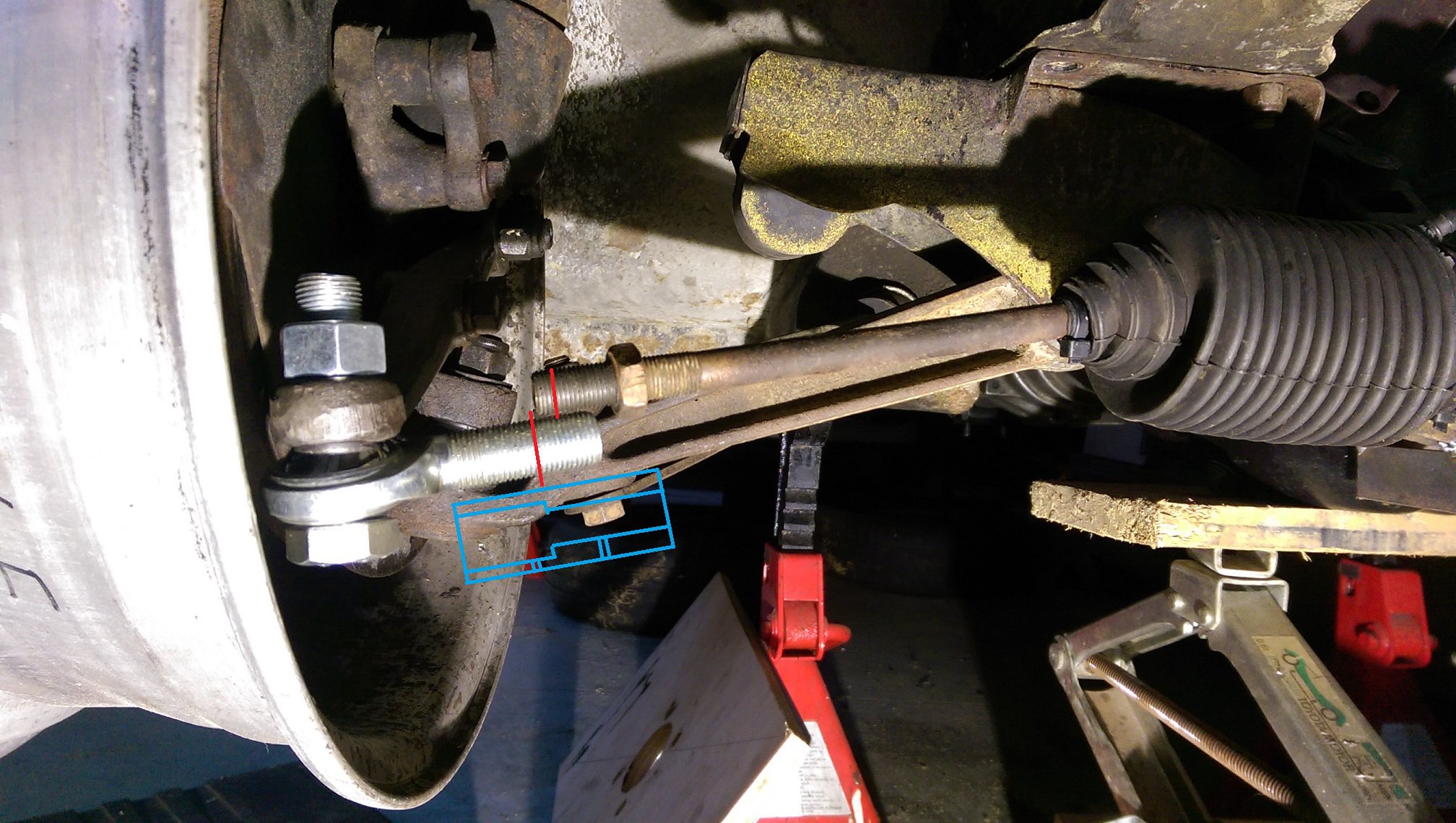
So I've lowered the rack in the Triumph to clear the bottom of the engine. To sort out the bump steer this will inevitably cause, I also need to lower the tie rod end. Normally, the tie rod end mounts on the top of the steering arm. I've drilled out the tapered hole to take a 5/8th" bolt so I can use spacers to get it to the right height. Everything is just mocked up with clamps and spacers while I work out where it needs to be. I just had these rod ends lying around and will probably be using different ones, but they will be the same bore/thread size. This is where stuff would be if it had the factory tie rod ends on it. As you can see the tie rod and or rod end are too long. The rod end is 5/8" unf and the tie rod is 1/2" unf. The thread on the tie rod cannot be extended as the diameter reduces after the thread. My initial idea is to shorten both where I have the red lines. And use a threaded joining thing, in blue, to join them. I think I would have the rod end always threaded all the way in, with thread lock maybe and do the adjusting at the tie rod end like a 'normal' car. Does this look okay? Is there a better way to do it?
-
I've still got a rod in my leg. Doc told me that if there is high probability I would break the same leg again, it would be removed, otherwise they leave it in. Reasoning was that if the rod bends at the break, it makes it rather hard to get out.
-
So there was a skyline at pickapart and I thought I would have a go at trying to remove the rear subframe studs. I had a chisel with me to open up the top of the chassis rail so they could be driven out. Because apparently they are pressed in. I hammered, with the mallet, on that first stud for ages and it didn't move, so either it's REALLY fucking tight or the big washer that's welded in is not a washer and it's part of the stud. But I think it's just really fucking tight, I was starting to deform the stud, so if I ever did get it out, it would have been unusable. Needs angle grinder.... Is anyone wrecking a RWD early 90's nissan and can cut the studs out for me?
-
I've heard soggy wet newspaper is also another less messy method.
-
Dude, you have SO MUCH room compared to my Triumph engine bay! I've got about a 40mm square space on the cross member between the block and the steering universal to 'grow' a mount out of.
-
Watch out. I've noticed that fisholene like some rubber. Makes it all soft and sticky then go hard as. It turned the rear sliding windows in my mini estate into not-sliding windows.
-
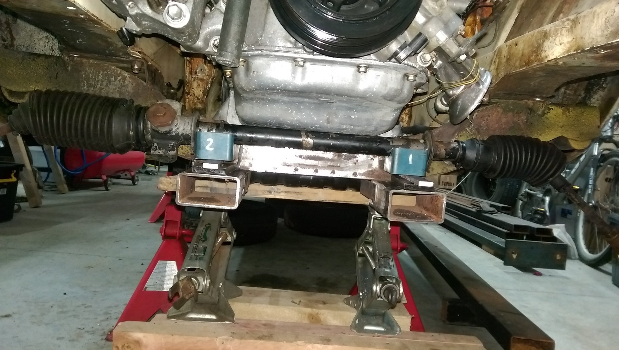
So I've notched the crossmember so it fits under the sump. Then tacked a bit of box section in line with the steering rack mounts so I have a reference. Then I cut the rack mounts off. This is me trying to mock the rack up in the right place.
-
I supposed if you had 'gridlines' turned on it should work.
-
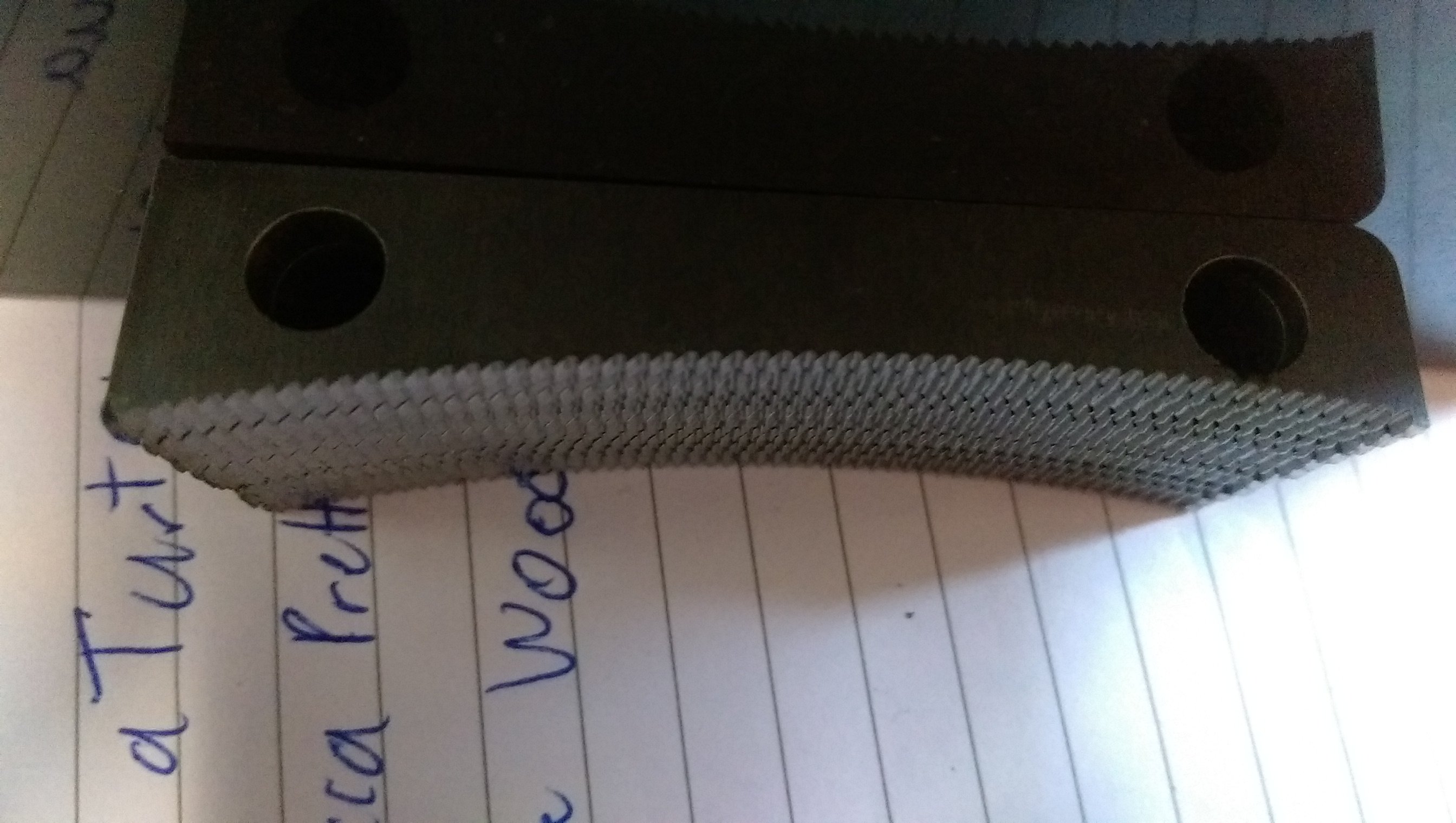
That's the plan, but I'm at work and I don't think the files on my computer are sufficiently abrasive.
-
@flyingbrick I lined them up best as I could to take the photo. There is a bit of a bump on the back edge where the cut starts/stops and some slag on the back of the cut that is making it harder to line the teeth up properly.