Adoom
-
Posts
2193 -
Joined
-
Last visited
Everything posted by Adoom
-
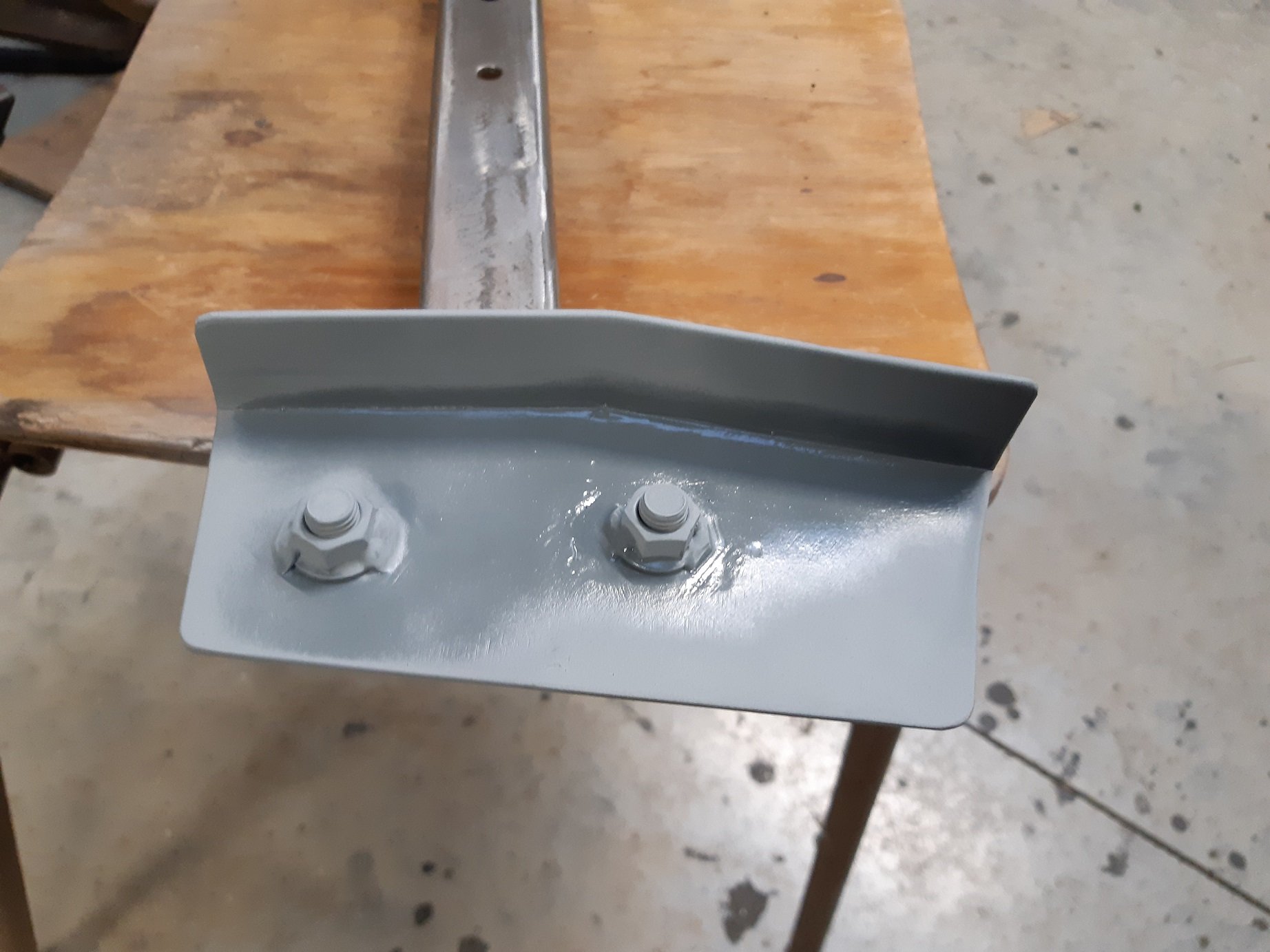
I had worked on this last weekend but didn't take any photos. Captive nuts welded to strengthening plates. Straightened welding warpage in strengthening plates. Embiggened holes in chassis rail to clear captive nuts. Cleaned, sanded then acetoned chassis rails before spraying with some zinc 'weld through' primer, that I'm totally going to wire brush off where the welds will go. Sanded the strengthening plates and zinc primered them too.

- 191 replies
-
- 10
-

-
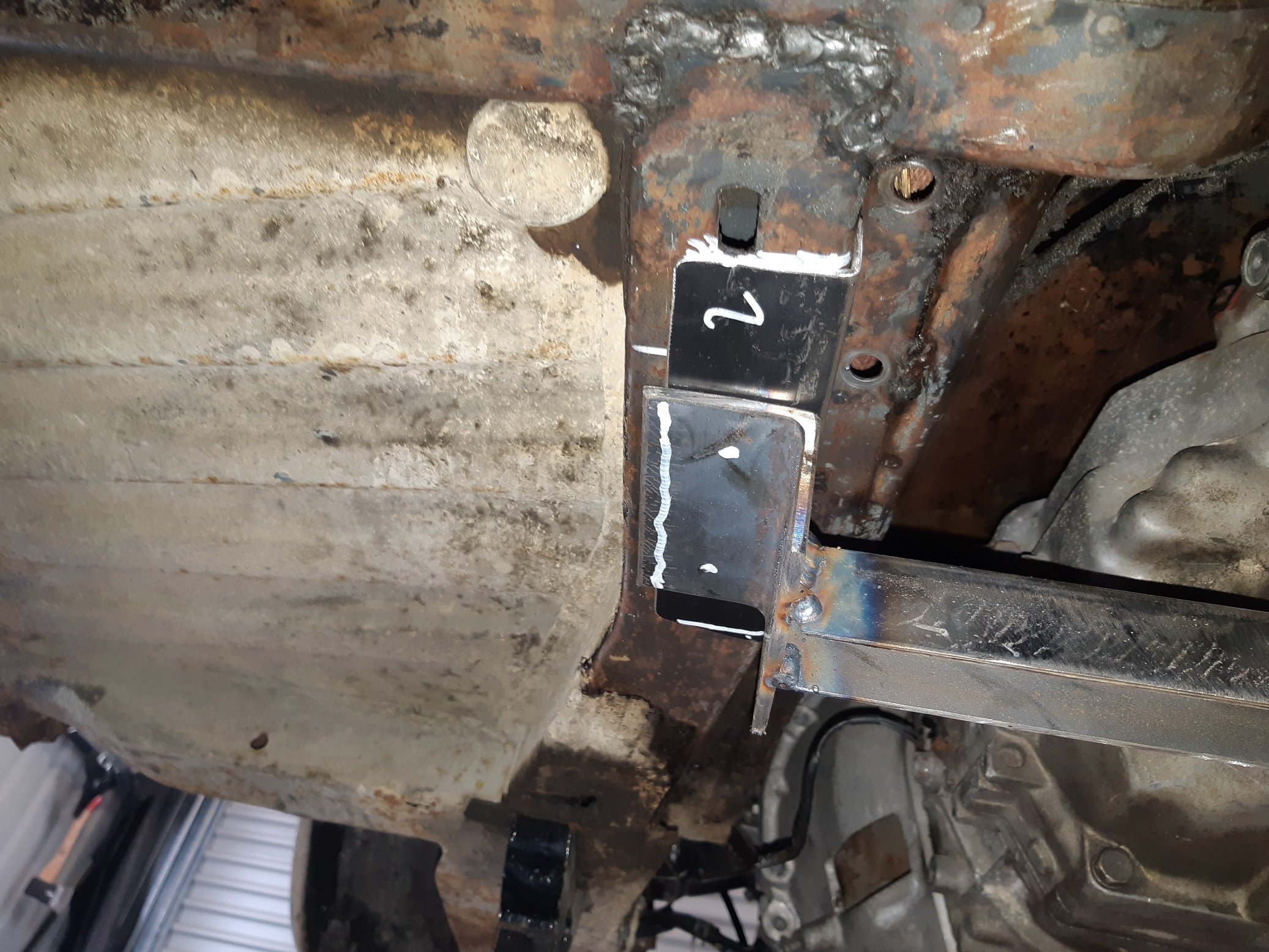
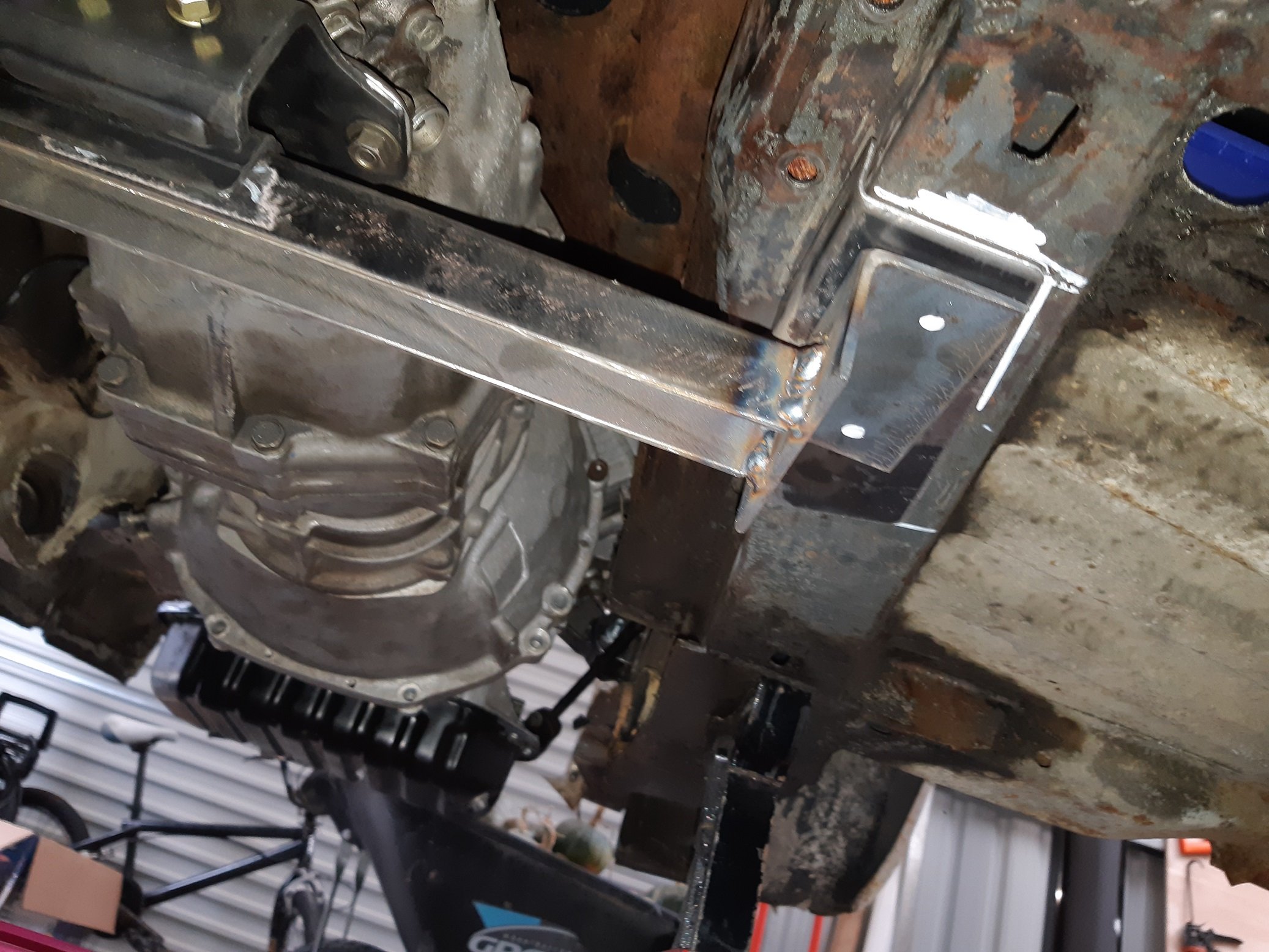
Been working on the gearbox cross member. Made up some 2.5mm strengthening plates to weld to the chassis rails. I will weld the captive nuts to these. I'll just tack the plates on for now and fully weld them when I make a rotisserie later.
- 191 replies
-
- 10
-
-
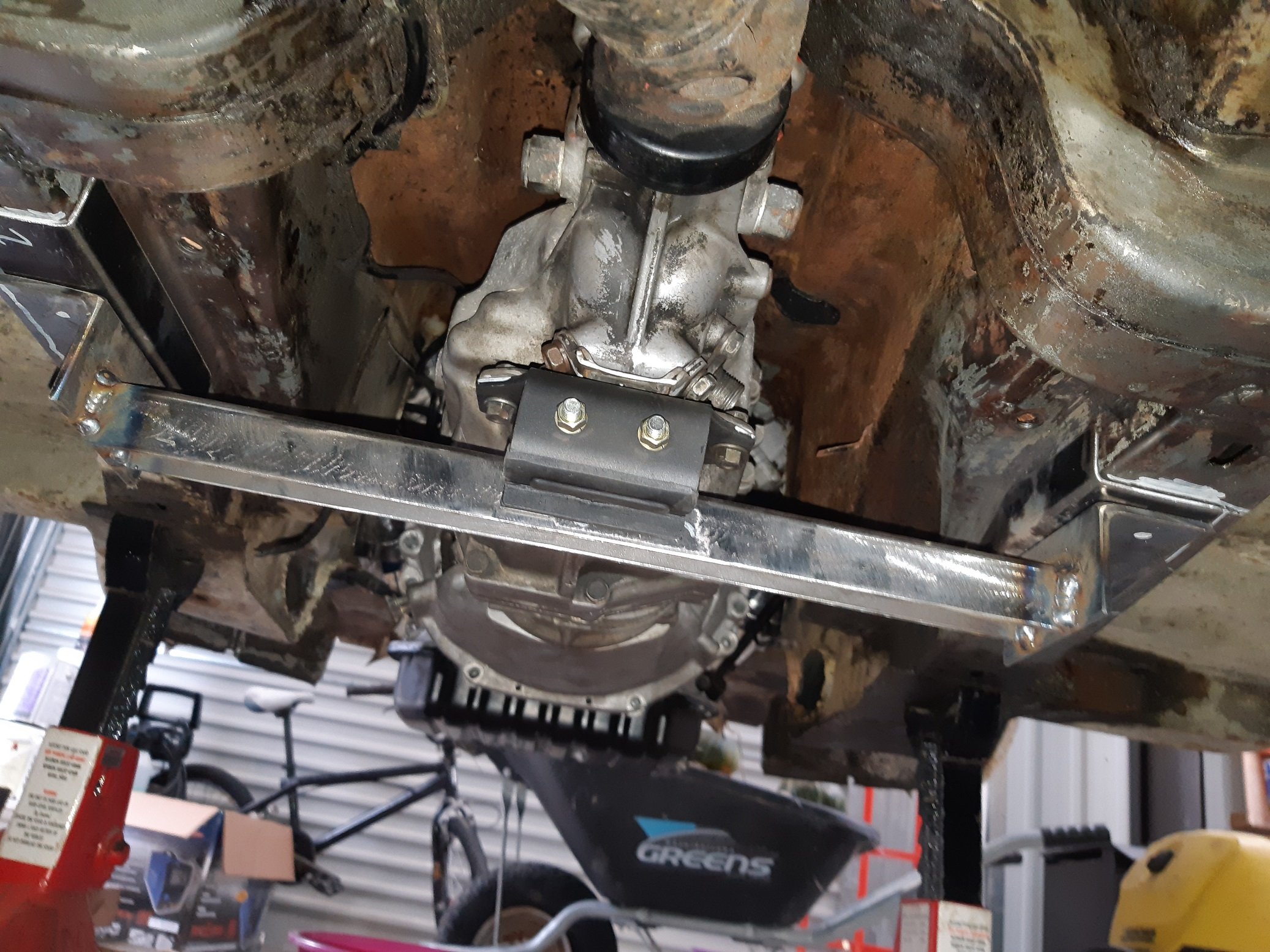
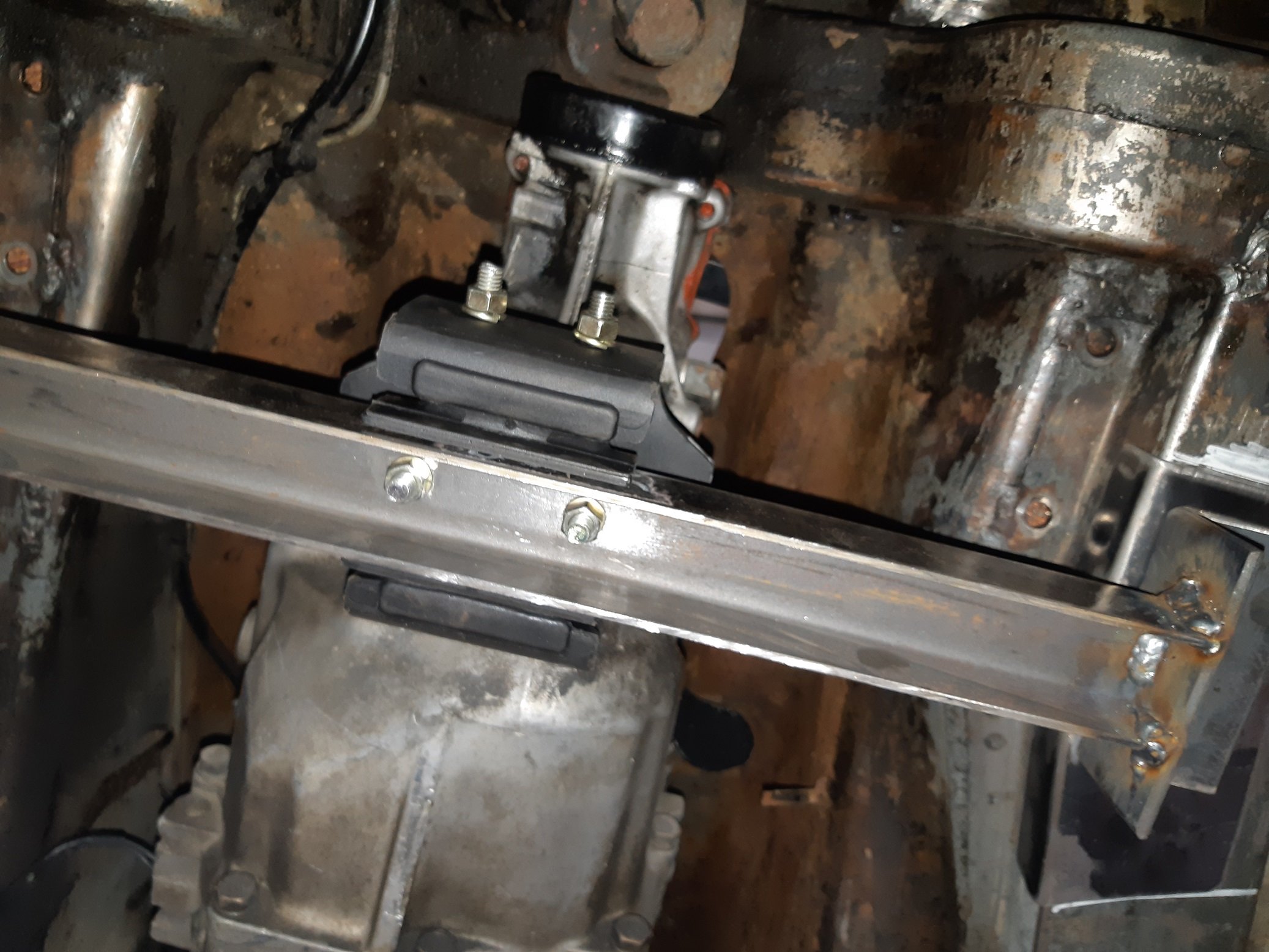
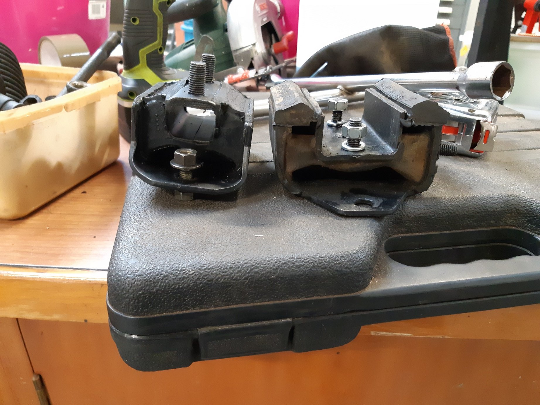
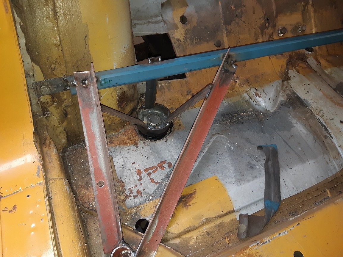
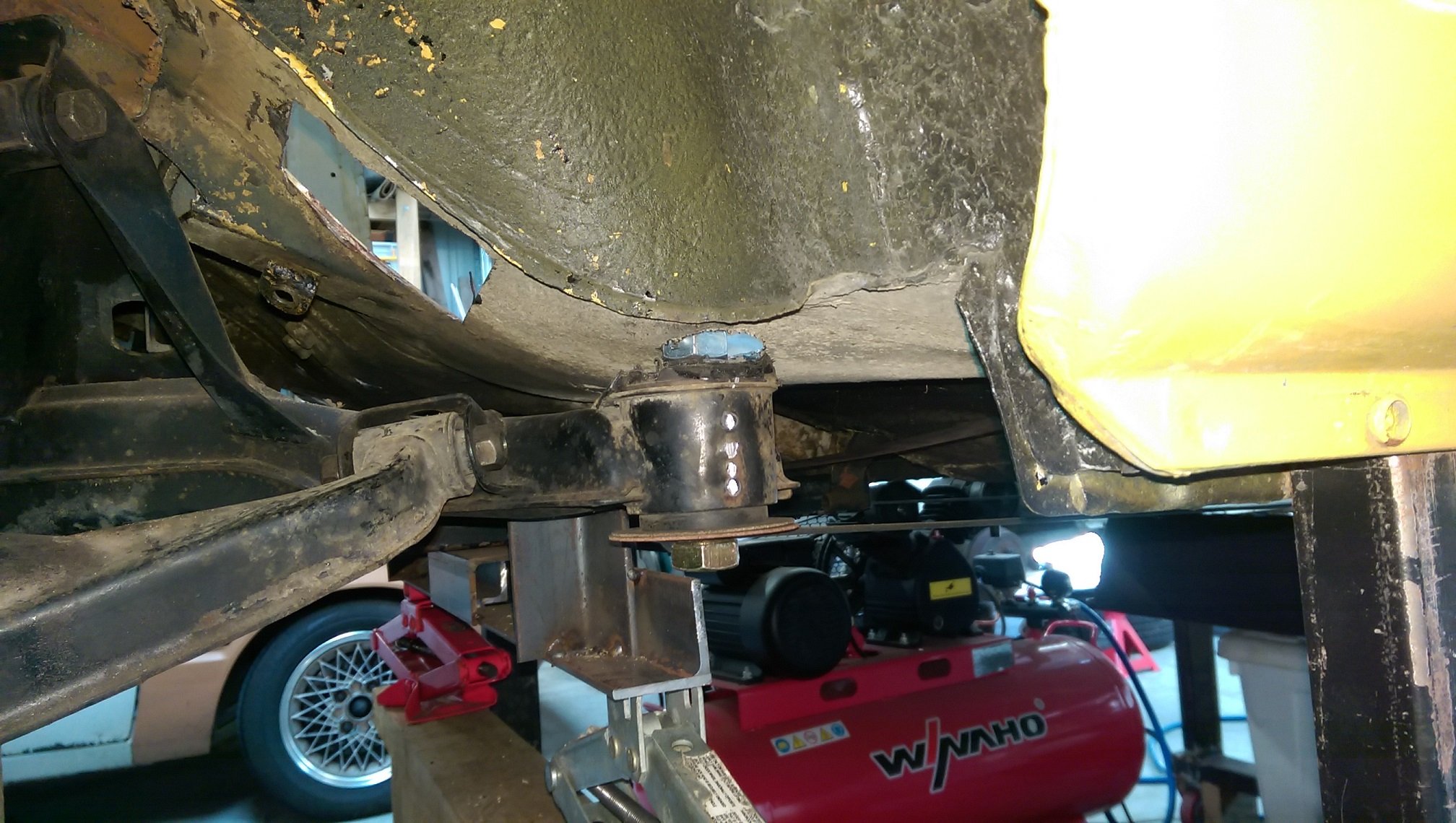
I'm a bit stuck, not sure what to do next... Decided to lie under the car and stare at the floor where the gearbox cross member needs to exist. It's a W57 box, so it has a weird angled 'V' shape where the mount bolts on. The previous owner of the box cut up that mount to make it into a flat plate so a different rubber mount could be used. It's the mount on the left, I don't know what it's from. If I use that mount, then add a cross member to it, it will hang much too low under the car. After looking at a photo of the factory Supra/W57 mount, that will also be too low. So I had a look under the Starlet, which has a CA nissan gearbox, and thought "hmmmmmm". So I borrowed the mount off the Starlet. The one on the right. If I use the modified 'V' bracket thing and the nissan mount with some 40mm box as the cross member, it will hang about as low as the factory Triumph mount.
-
Speed up the process eleventeen billion percent by strapping it to a car wheel instead! I'll just let myself out.--->
-
Welds look good. You know the trick of putting a bit of copper behind the weld? It really helps with blow through and doesn't stick to the weld. I just use a bit of flattened copper pipe.
-
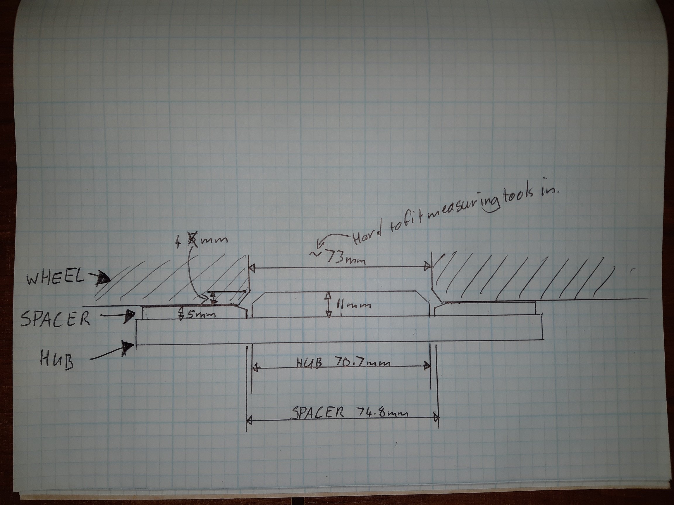
I just went and had a measure. It would need to be super skinny, with a step in it. Could I machine down the diameter of the hub spigot and press on a steel sleeve to make the spigot taller, and a more better diameter? Maybe 70mm and extend it right into the wheel, so I could just stack two spacers? Here are the measurements I took. Note: the taper on the hub spigot is part of the casting, so it's not uniform.
-
I need to make some wheel location rings. What materials are acceptable. The diameter on the hub is too small for the wheel spacers and for the wheel center hole.
-
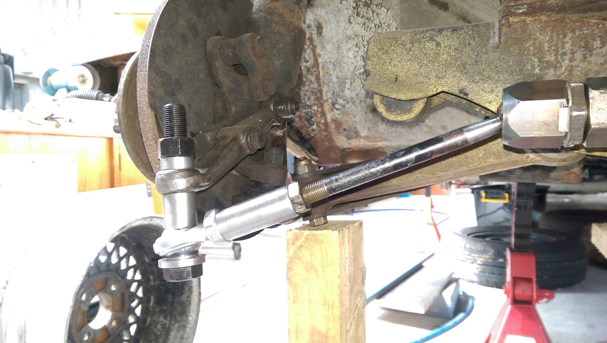
So I fitted my modified cross member to the yellow one to use as a reference to work out what's going on with the rear alignment. With the rack in the center of its movement, and both tie rods bottomed out on the rod end, the right wheel toed out and the left wheel toed in. After much fucking around I found that the centerline I had marked on the cross member, which I aligned the rack with, was 4mm too far the the right. So I moved the rack mount jig thing over by 4mm. Now I could align the front wheels more or less straight and the adjustment on each side(exposed thread) was within 1mm of each other. Then I used a plumb bob to mark the center of each wheel on the floor. Both sides were the same 2713mm! And took some other measurements to draw on the car... The front and rear track, measured from the outside of the wheels, is pretty close. The front has 3mm spacers(washers) for clearance. I've got some 5mm spacers coming. I'm undecided if I will also put spacers at the rear. I also ran a string line between the front and rear wheels. Left side has as close to zero toe as I can measure. Right side had a bunch of toe out... Not sure why. I dialled it out with the factory eccentric bolt, but it used up almost all the adjustment. I supposed I could get some adjustable track arms if it needs them.
-
Hmmmm, I guess I'd have to reinstall the front suspension and steering to the yellow shell and drag it to a wheel alignment place.... Extracting it from the garage will be a mission. Unless there is such a thing as a mobile wheel alignment, or is all the gubbins tethered to some doodah?
-
That was the conclusion I came to as well, but I'm befuddled as to how the fuck I should know when it's straight and the car is not going to drive in circles when it should go straight.
-
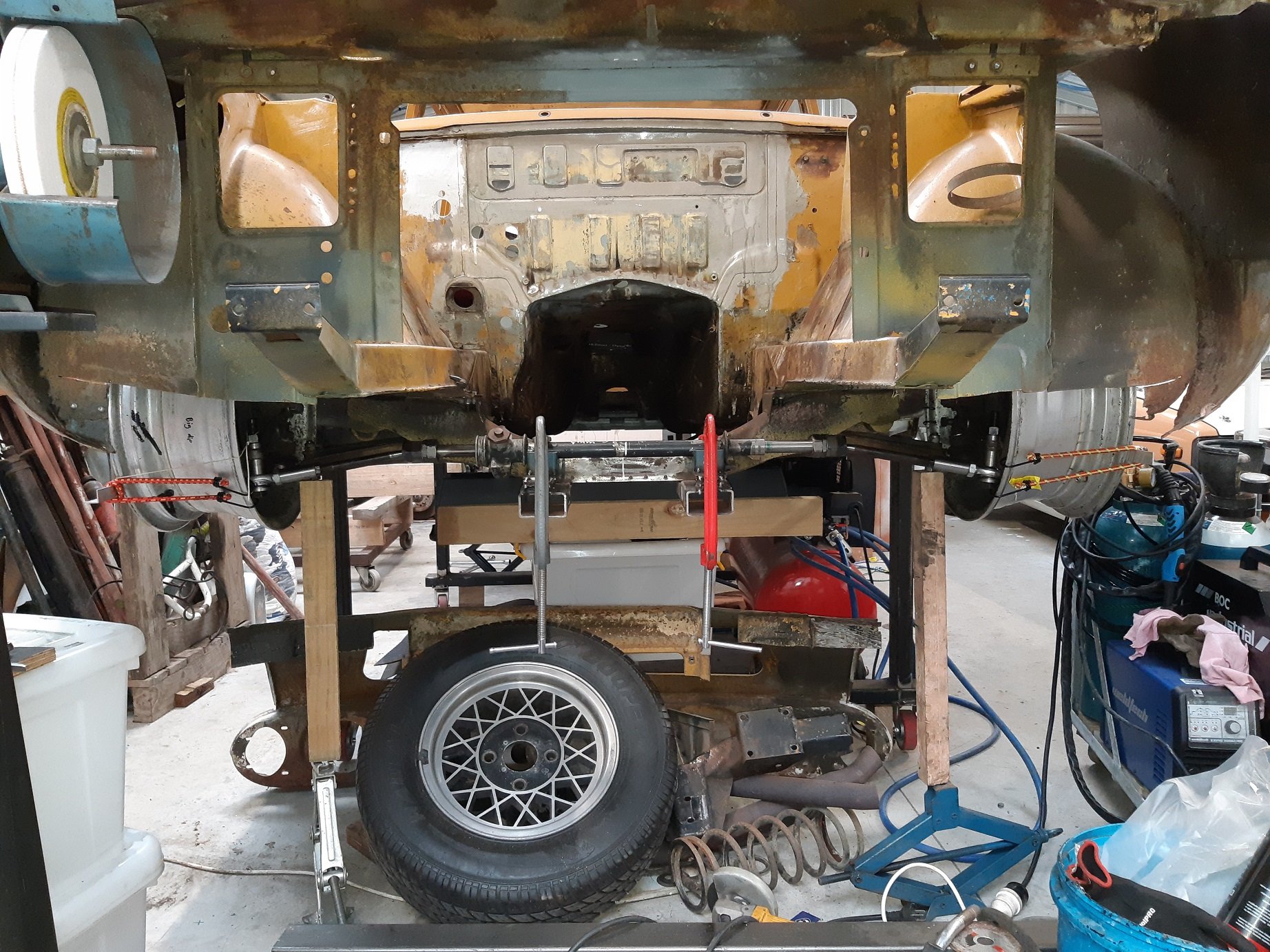
AAAAAARGH!! So with my two triangles connected to the subframe mounts, lined up with the centerline of the car and using the factory body reference points, I thought the subframe must be pretty straight. Now I have reinstalled the suspension and wheels(no tyres). I don't know what measurements to trust. According to my triangles the subframe is straight. But with the wheels on I have measurements that disagree. The factory adjustments are set to max toe out and max neg camber. Both sides are at the same height. If I put a straight edge vertically against the wheel, both sides sit 20mm in from the top of the wheel arch. So You would think "it's in the middle". I used a plumb bob to see where on the wheel arch the wheel center was and marked it on the wheel arch. I was having trouble getting an accurate measure using just the rear guard, so I measured from the mark to the A pillar (2030 both sides) and the B pillar (right side 1128, left side 1122) and the leading edge of the rear guard(right 365, left 364). So both wheels are the same distance front/back, right? I've measured from the centerline of the car to the flat bit on the lower part of the sill, along the whole length, on both side of the car, the measurement is the same within about 5mm. So I thought I could use it to measure the toe angle. So I got some 1800mm lengths of aluminium angle and attached it horizontally to both wheels. Then measured the distance between that and the sill(over a distance of 1300mm). According to that, the right wheel sticks ~10mm further out than the left wheel?! The right wheel toes out by 0.8 degrees and the left wheel 0.2 degrees. Sure I could adjust that out, but I shouldn't need to and AFAIK it's a large percentage of the available adjustment. Or I could rotate the subframe anticlockwise(looking from above), but that would move the right wheel forward and the left wheel back and put my triangles off by heaps. So what's right and whats wrong? A wonky subframe could cause it, but I would be surprised if my narrowed subframe was wonky, the jig I used to narrow it was/is substantial.
-
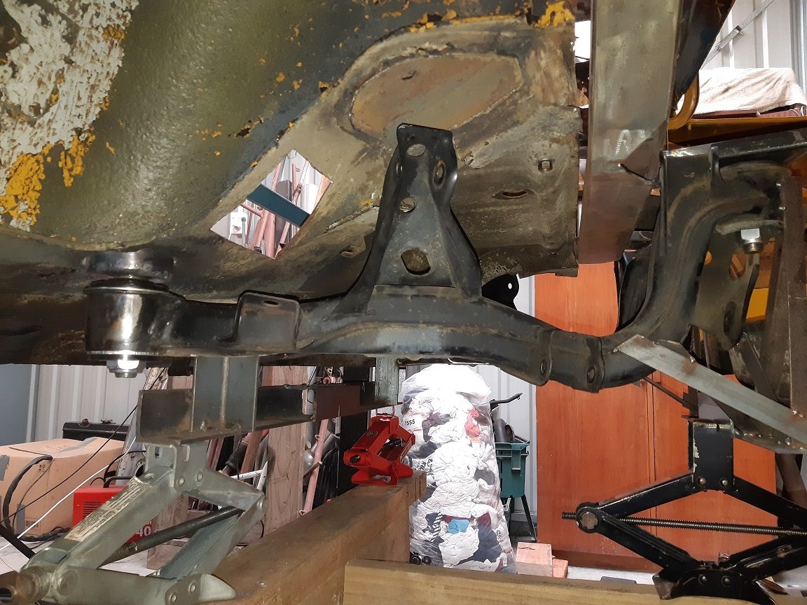
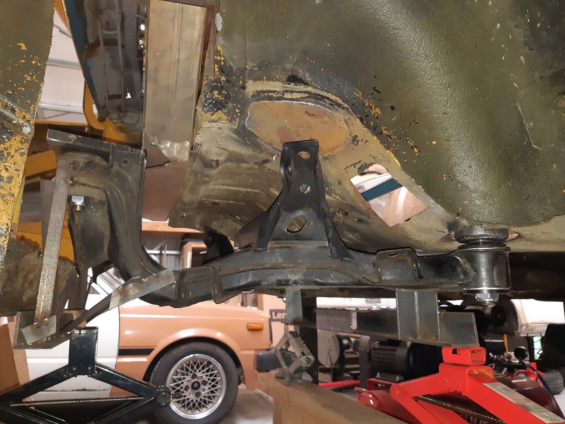
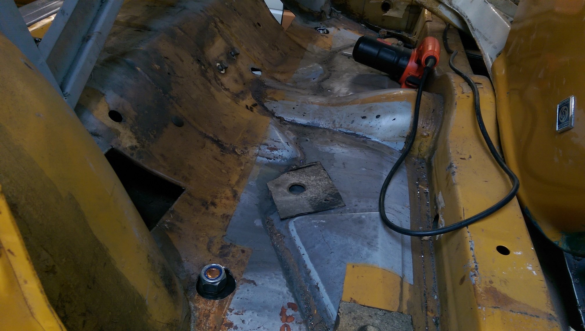
Subframe front mounts and the jig to allow me to transfer it to the other car. My current thinking is to plate the floor and some of the wheel well, around the front mounts, with 2.5mm, on the inside of the car. If it's not solid enough, I'll tie it into the sill.
- 191 replies
-
- 11
-
-
I think track measurement is tread center to tread center, not mounting face to mounting face. Both the Nissan S13 and Triumph 2500 track info I found was not face to face.
-
Do you even need reverse? Since it's basically a mini and mini weight. Several times I reverse crash started mine by pushing it backwards just with the power of one leg out the door....
-
Wow! Slow down you maniac! You put the rest of us to shame.
-
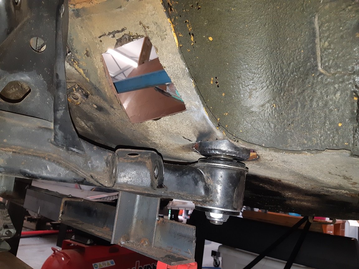
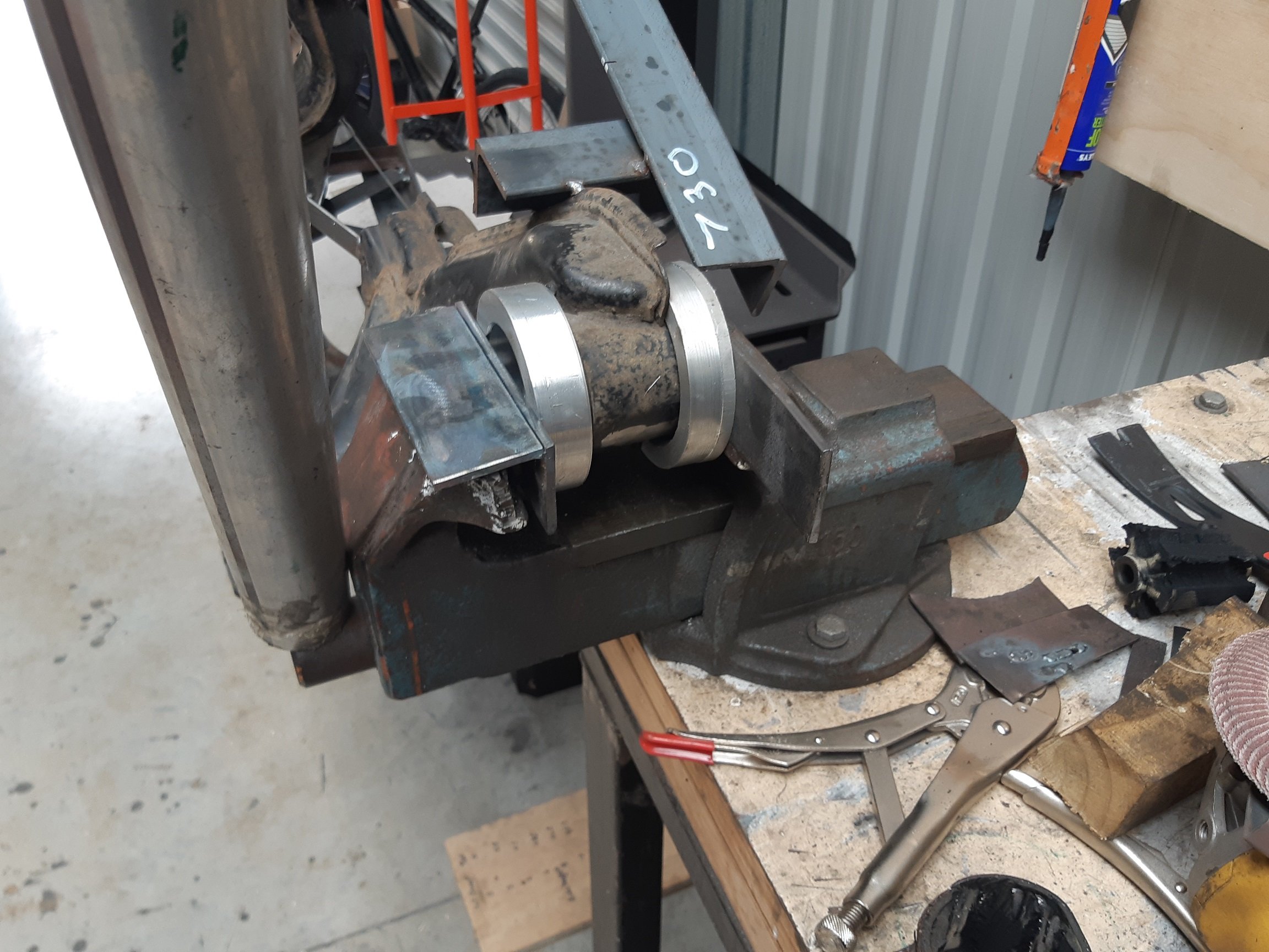
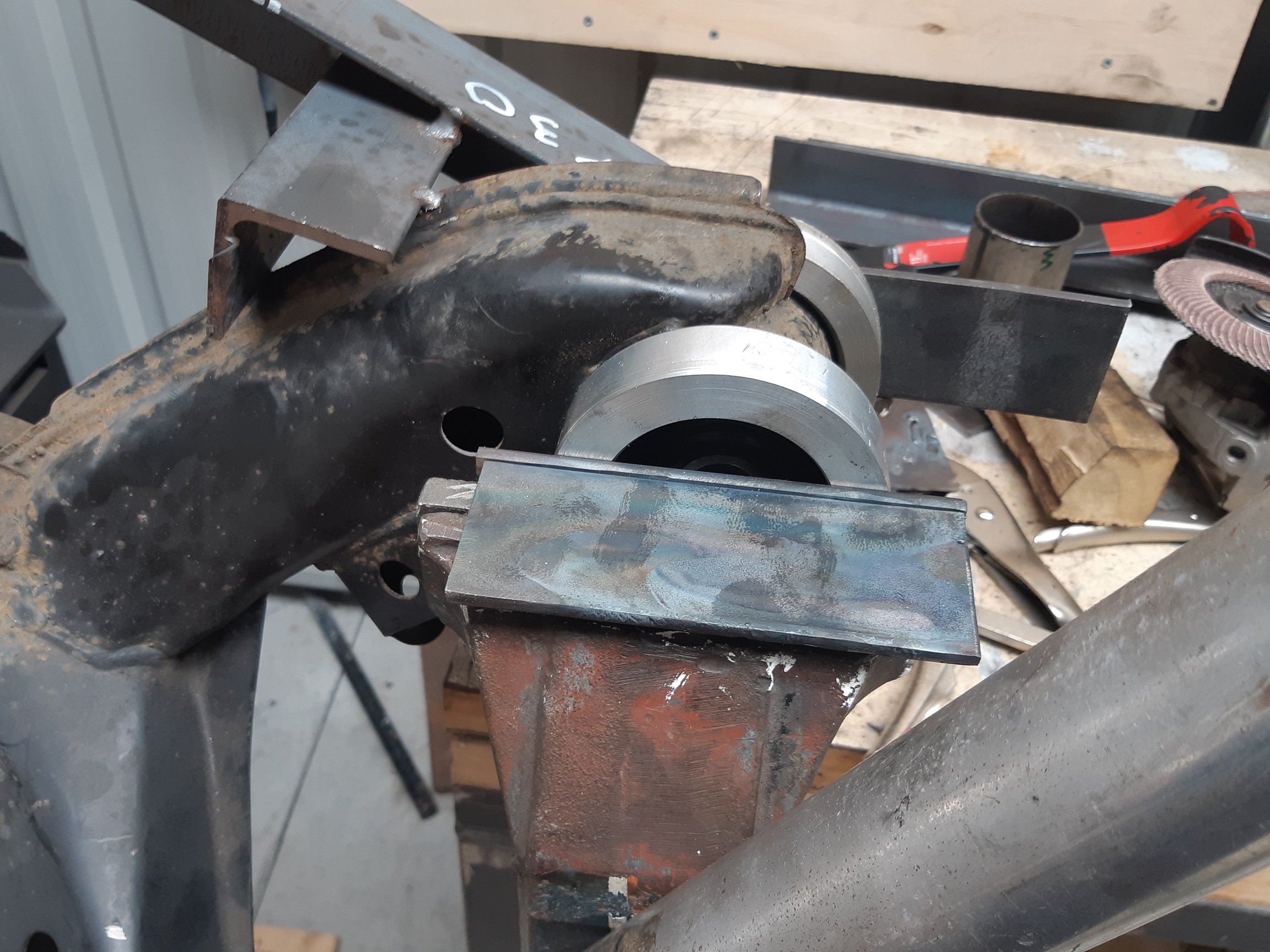
My replacement subframe bushes arrived last week. I thought I should at least replace the wobbly front ones before I weld in any mounts for it. What a bitch of a job. The bush is bonded into a metal sleeve and that is pressed into the subframe. I drilled a bunch of holes through the rubber until I could get the center of the bush out, then I used the reciprocating saw to cut into the metal sleeve. After putting a couple of slits in it, removing the remains of the bush was easy. Despite being careful, the imprecise nature of the reciprocating saw meant I cut a bit deep in one place and made a groove in the subframe. But I was able to fix it up with the tig. Then I had to press the new bushes in. Hammer? Nope. G-clamp? Nope. Bit of exhaust pipe kinda the right diameter and using the vice? Sort of. I ended up having to make two alloy rings. One to fit around the top of the bush and press on a metal lip. The other as a spacer because the bottom of the bush protrudes about 10mm. And the vice, with a cheater bar. My poor vice. Oh, and to make the rings... I used a holesaw in the lathe, which took a million years because I had to back out to clear the teeth every 0.0000000001mm depth of cut. Then I asked the internet and found out about trepanning tools. So for the second ring, I made one of them out of the only HSS I had... 6mm square. It worked, but it was so thin it vibrated like motherfucker and cut millions of tiny needles.
-
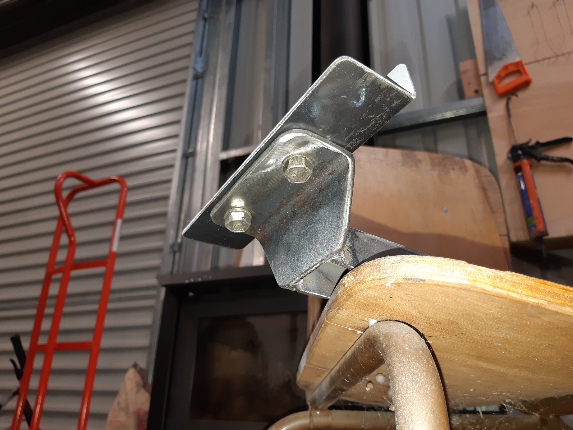
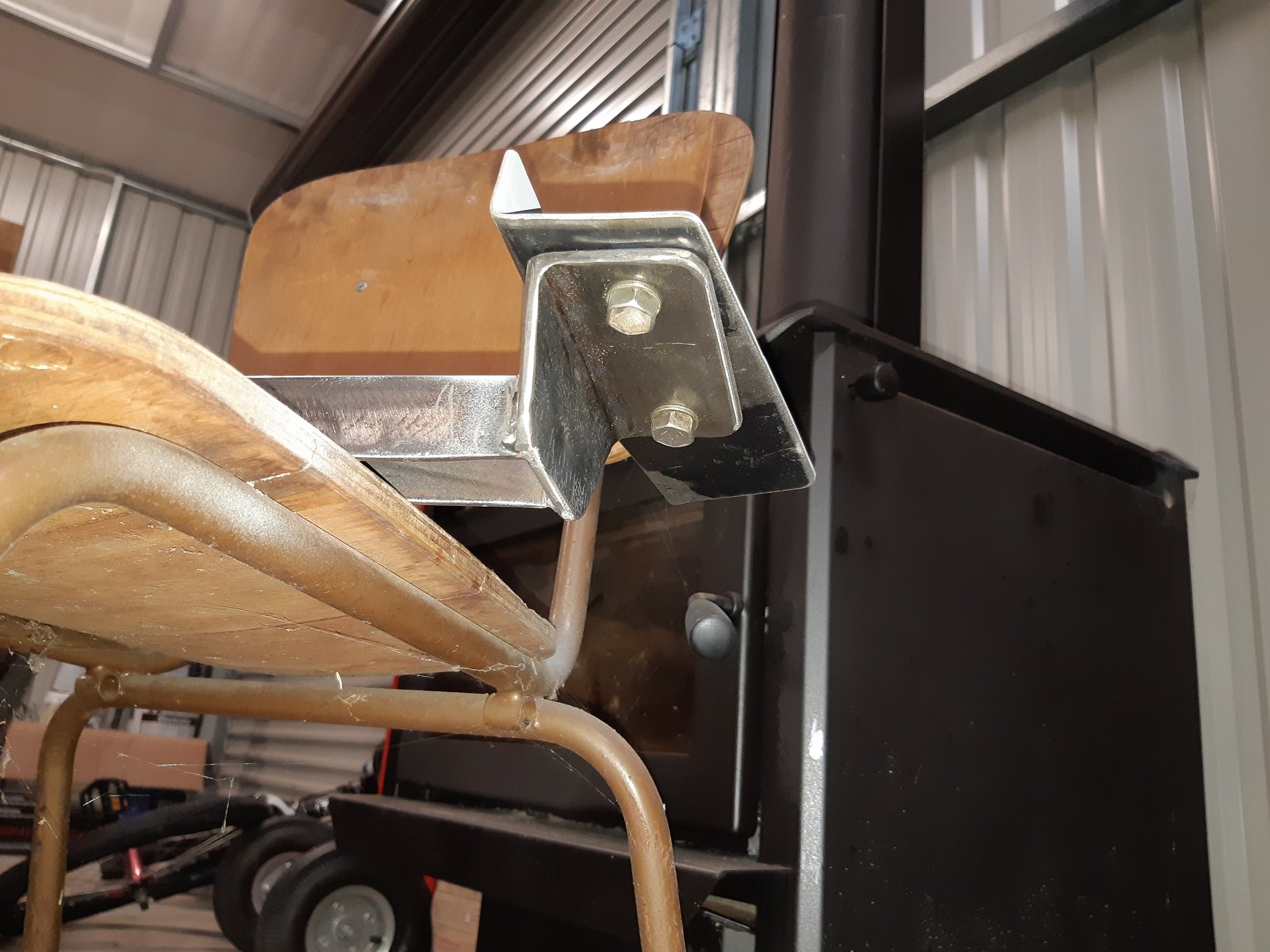
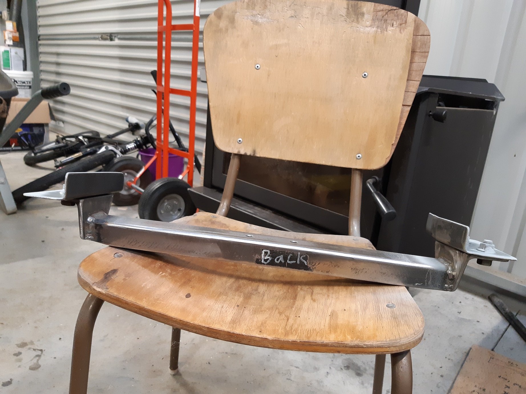
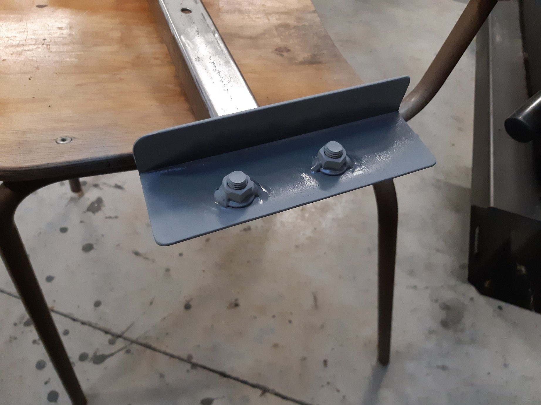
I made some additional temporary 'jig' brackets that connect into the original shock top mounts. I made them removable so I can still get the cross member out.
-
The tiny holesaw kind? Carbide bit in a die grinder is great for spot welds. Especially if you are only keeping one of the panels since it is easy to chew a big hole.
-
I have suspicions that this might be the same "M3" I saw many months ago, sometime last year, being driven through Lower Hutt, by a skinny guy with possibly a shaved head. It only got my attention because the car looked tidy but the number plates were super fucked, turns out they were for a Primera. /LING
-
Brackets And welded. Not completely, I'll take it off and weld underneath. Standing on a stool(because the car is quite high up) leaning into the boot is not really the most comfortable welding position.
-
For the diff thing. My 900 hornet does about 4000 at 100kph in 6th.
-
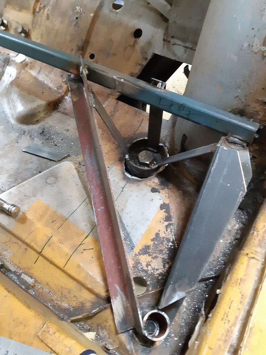
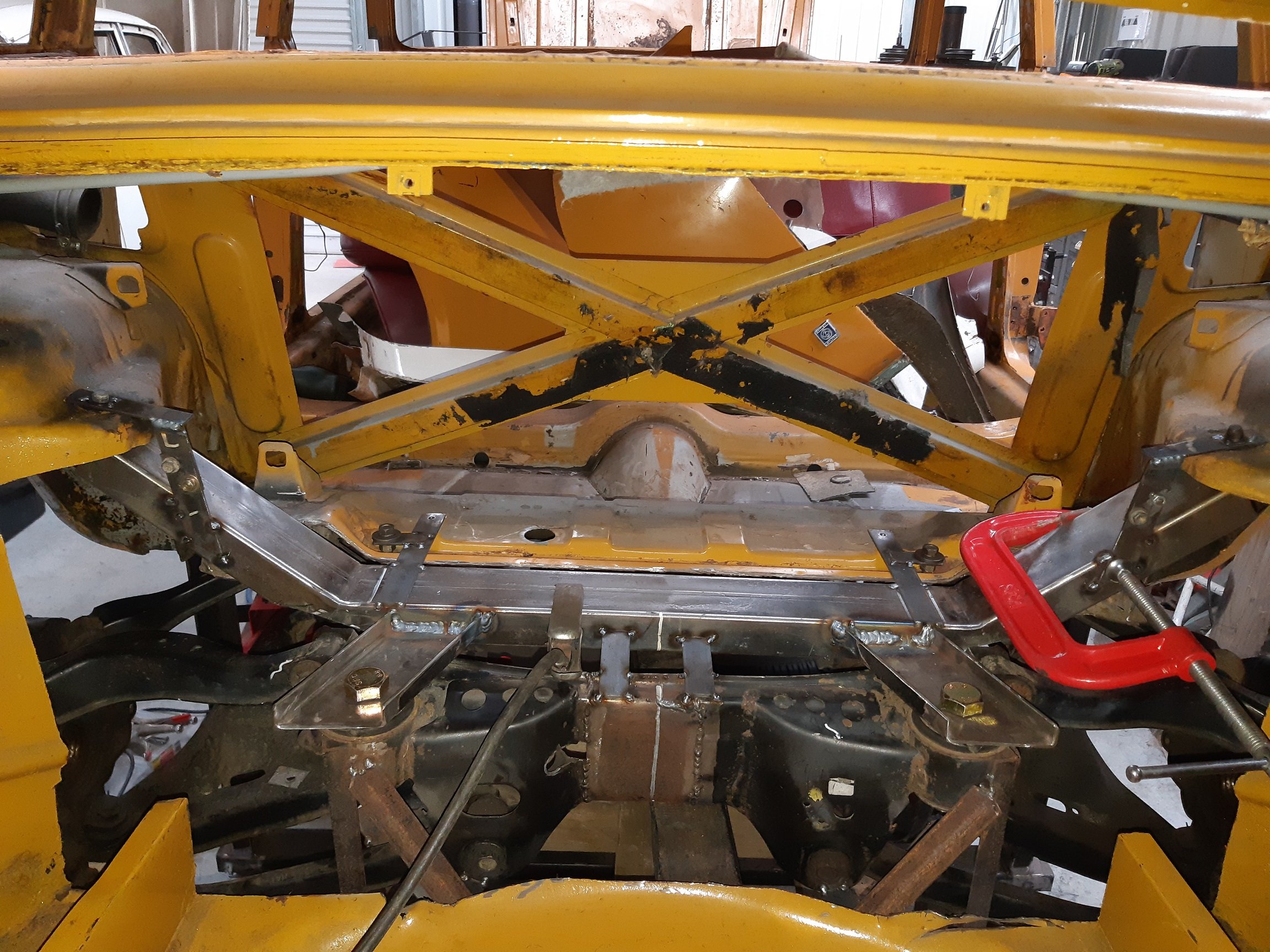
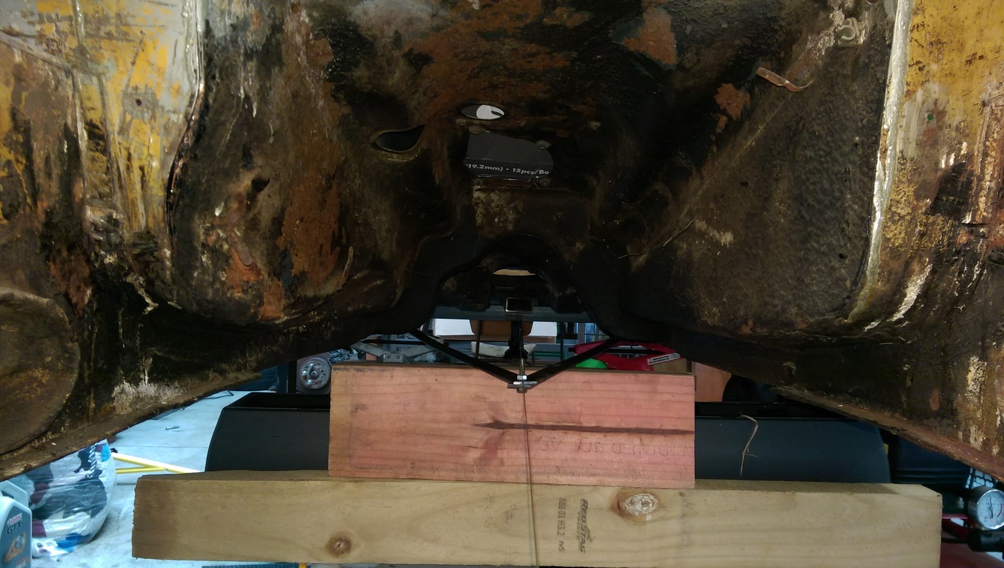
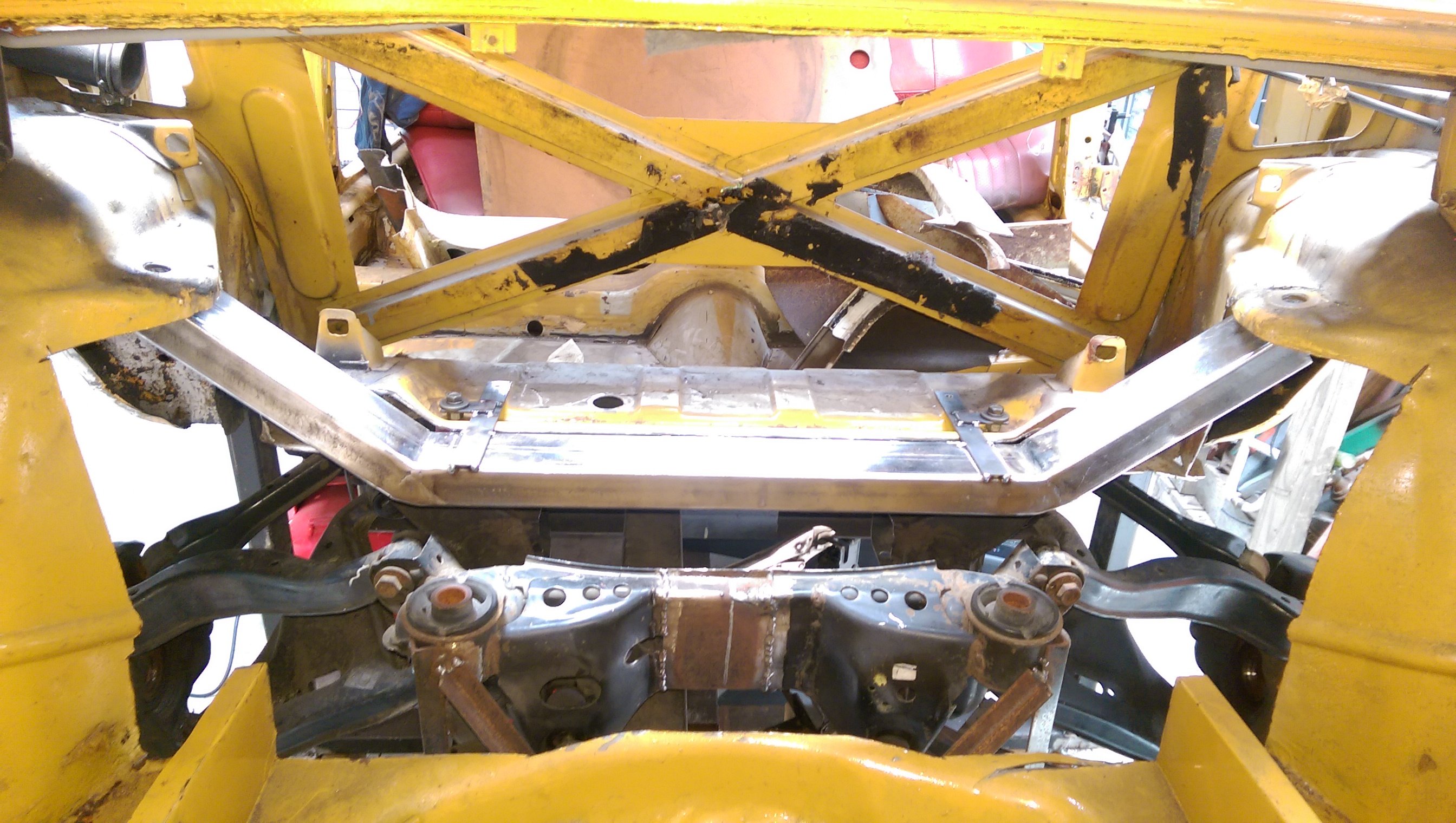
Using the body measurements in my factory service manual I found the centerline and ran a string down it. I made a much longer isosceles triangle from the front mounts and lined the subframe up with the center line. And raised the subframe up so the front mounts are not the lowest hanging thing under the car. The bolts are only there to hold the triangle, but I cut some holes to raise it up enough. They are higher now than the original triumph mounts. Yes.... I used some worn out cut off discs as washers. Then adjusted the height and measured it and measured it and measured it and measured it and measured it. Then temporarily welded it to my cross member so it doesn't move while I make the actual mounts.
-
I made an Isosceles triangle. For making sure the subframe is central and straight. I'll make another much longer one from the two front mounts. Unfortunately those two mounts are torn, they are almost falling out, and I need to replace them first.
-
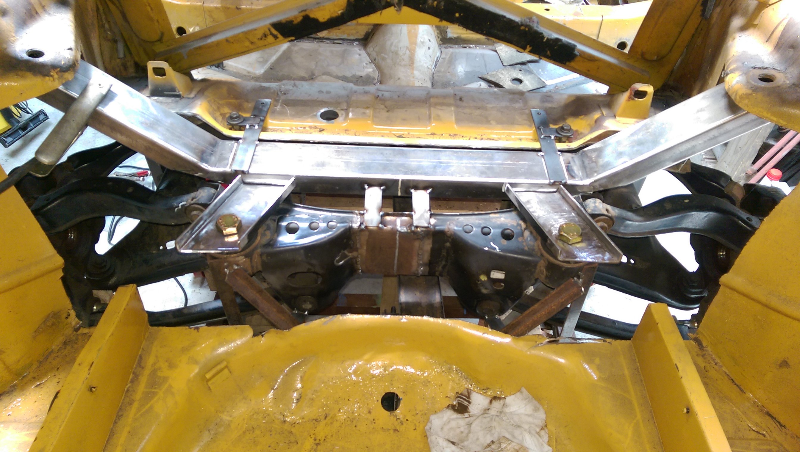
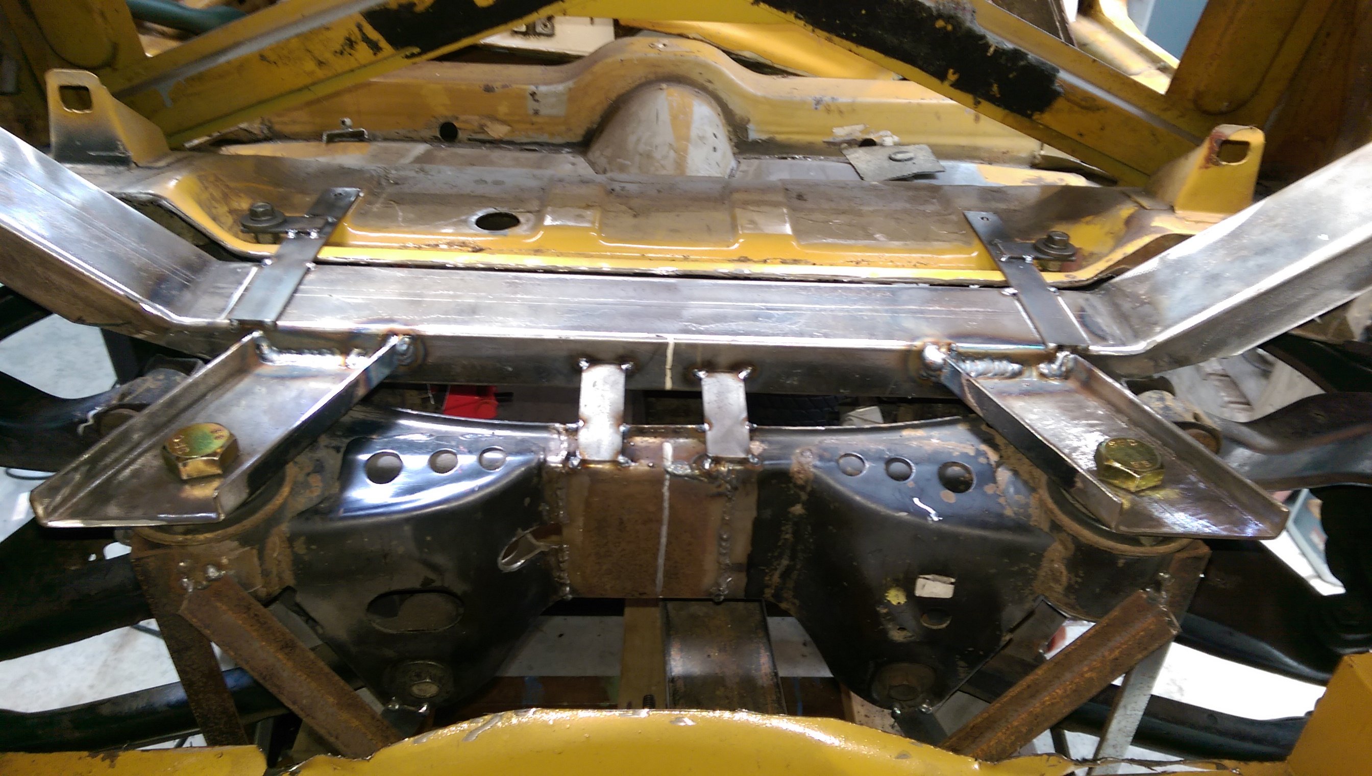
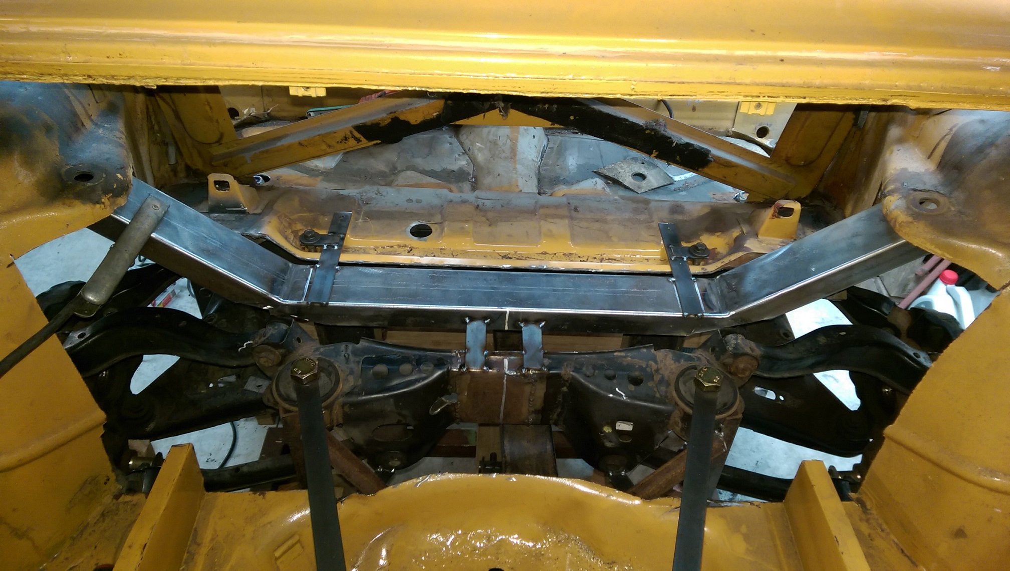
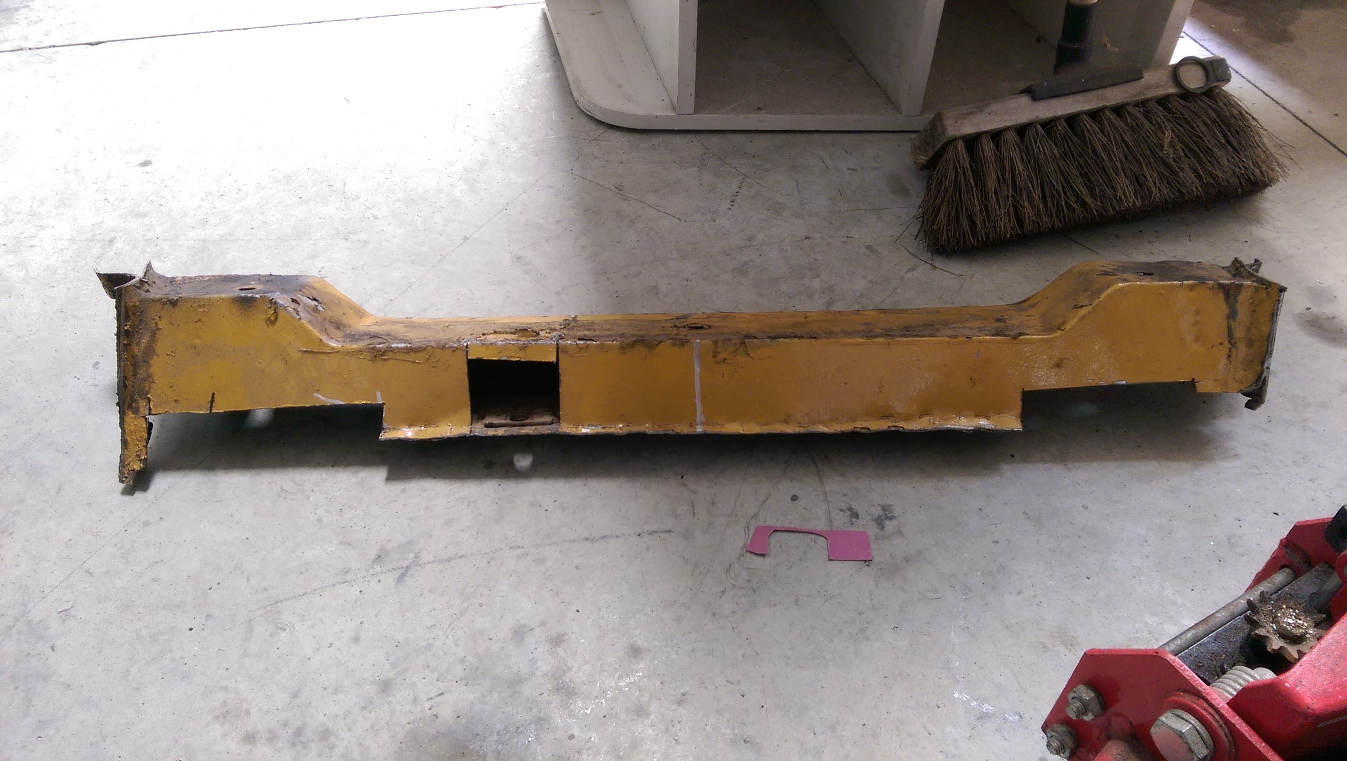
The existing rear cross member needed lots of modifications so I could get the subframe high enough and have room for the top suspension arm. I realised it was going to be WAY less work if I cut the whole thing out and make a new one out of box section. Snip snip. Those straps tacked to the top are my alignment jig, the bolts use existing/factory holes in the body. I don't want to permanently mount this since I will transfer it over to the white car once I've worked out how it will fit. The box is 3mm thick, so should be stronger than the original. I will tie it into the existing chassis rails which start just forward of it. The strut tops will be built off the ends of those angled bits, which I have intentionally made too long so I can trim them to fit. The angled bits follow the sides of the fuel tank, so it will/should still fit.
-
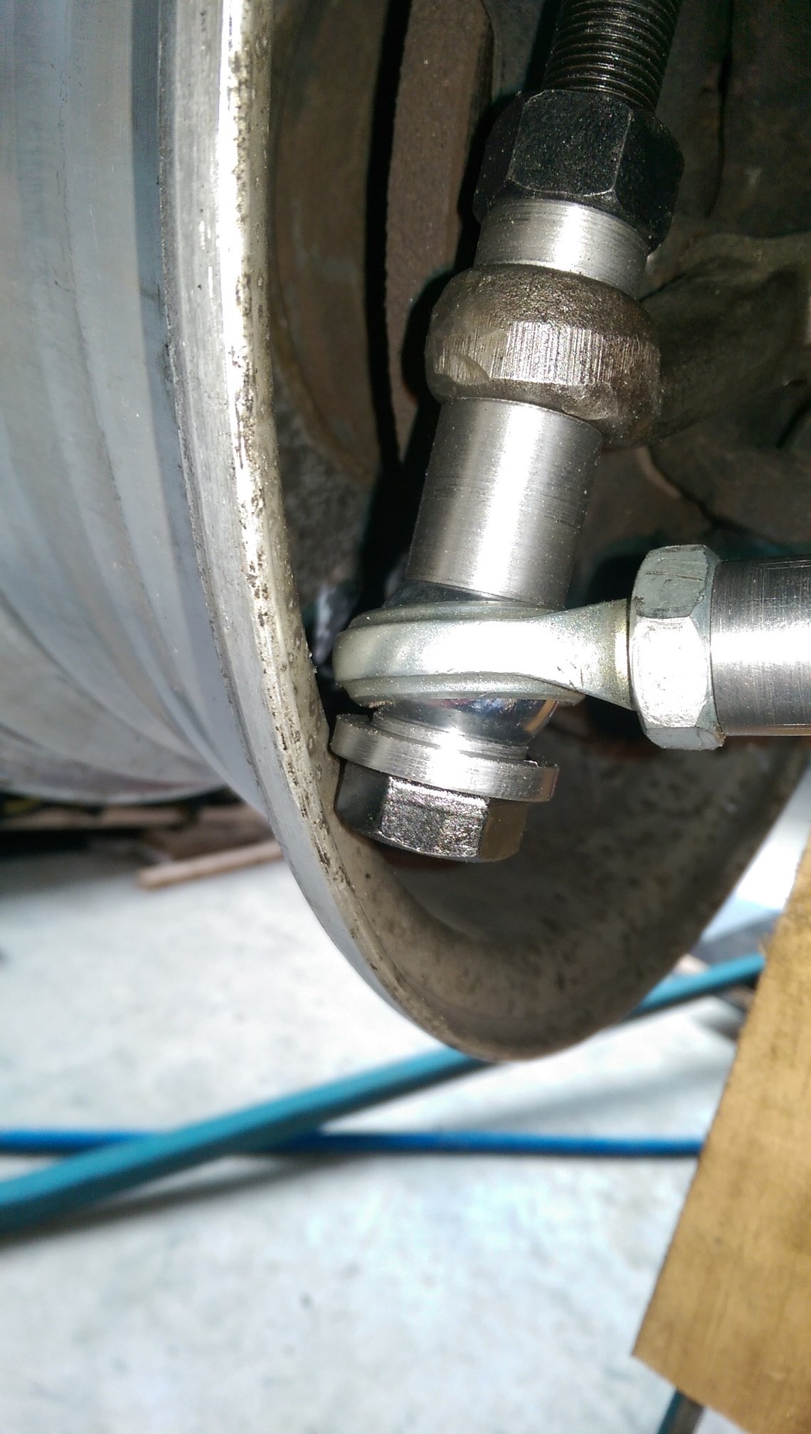
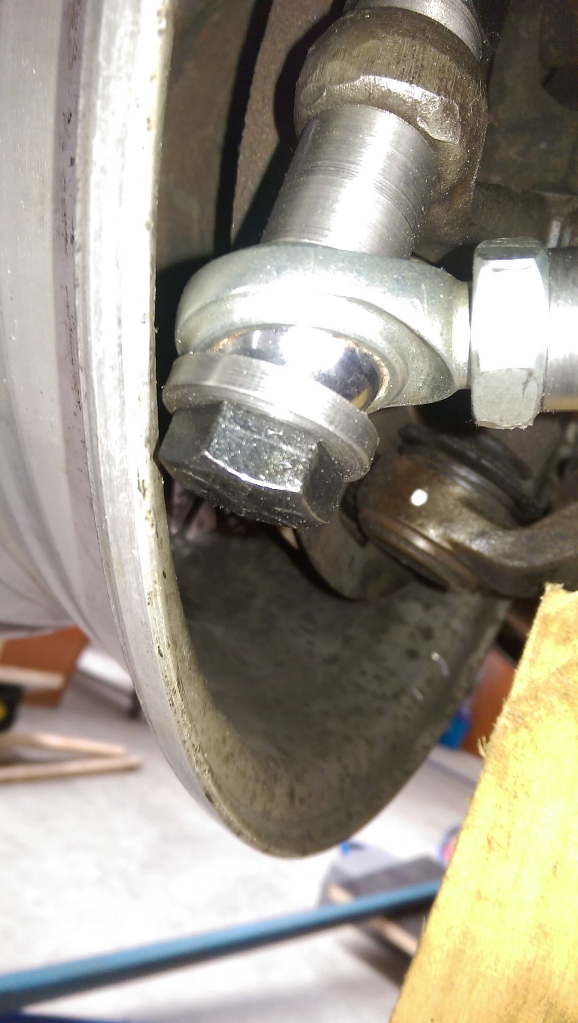
I made some round things with holes in them. I'm going to need to run 5mm wheel spacers(this is with 3mm washers).