Roman
-
Posts
6781 -
Joined
-
Last visited
-
Days Won
32
Everything posted by Roman
-
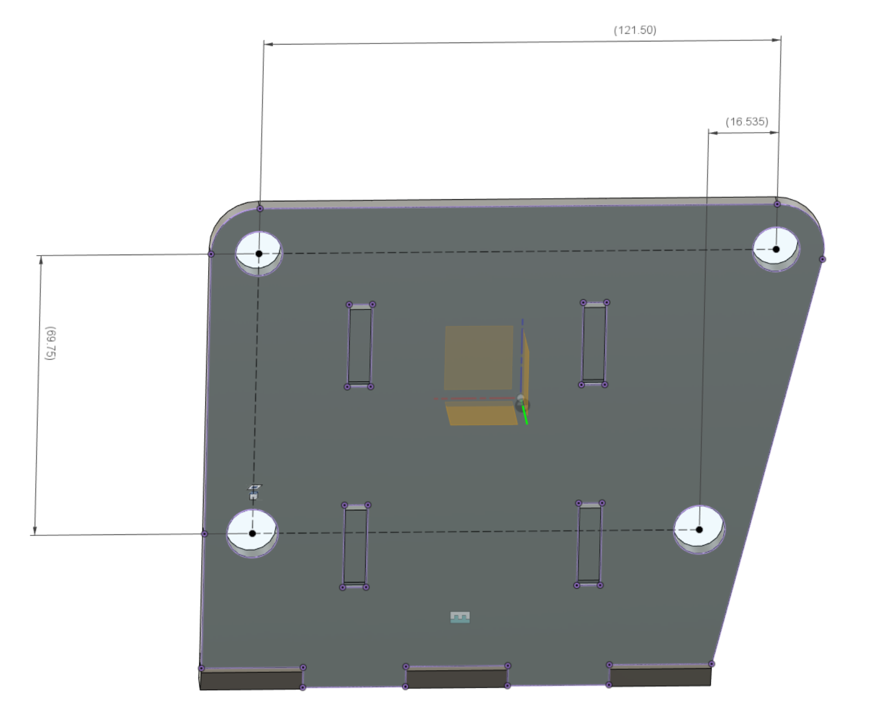
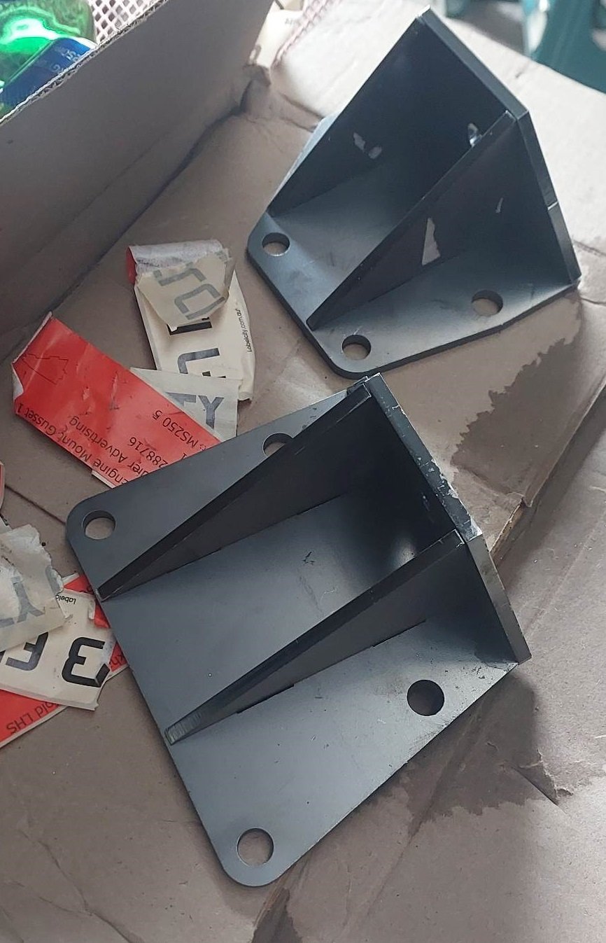
Sure. They're different left to right. This is the drivers side of the block, looking at the face that bolts to the block. Then this is the passenger side, looking at the face that bolts to the block.

-
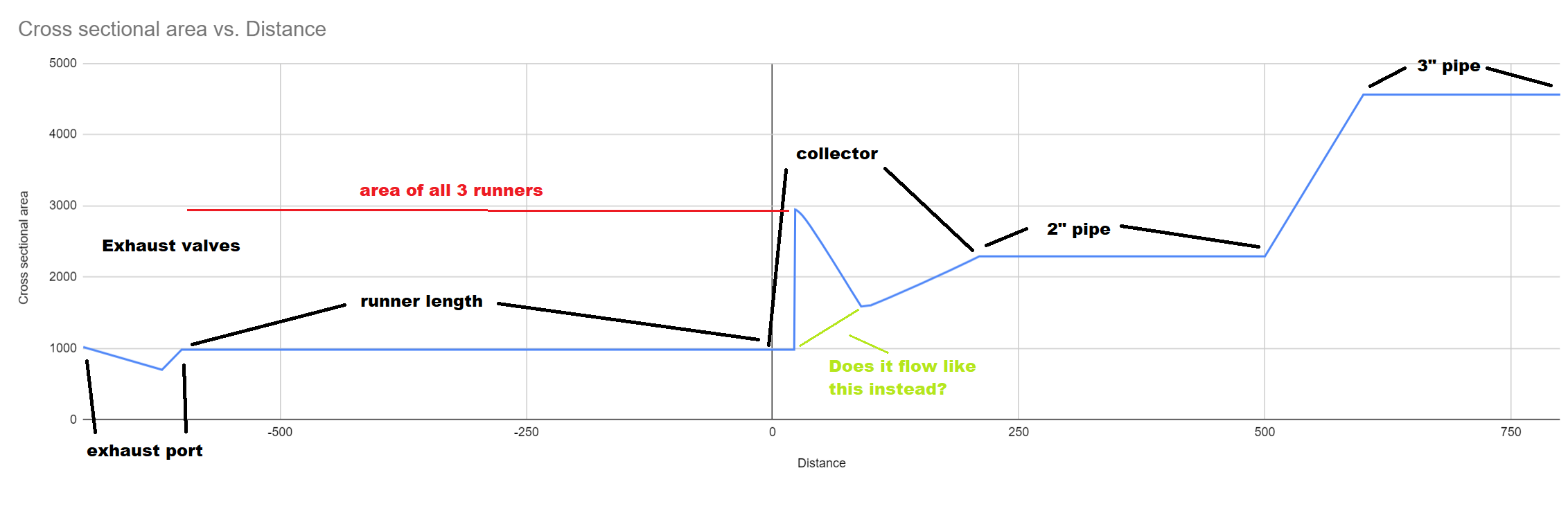
Completely off topic to anything and possibly not useful information. (Since when has that ever stopped me) I measured the cross sectional area of the collector at a whole lot of points through it. Then added cross sectional area of other known bits to show a map of whole exhaust. The cross sectional area stays exactly the same as the runner until a point where it near instantly blows up to the cross section of all 3 pipes. Then tapers down from there, then flares up again. The point in the collector where there's the big spike upwards, is here. It seems you cant do much to change how big or quick that spike is, except for by merging more cyls together or vice versa. However changing the collector angle changes how quickly it ramps back down to normal cross sectional area. I found a picture of the Alfa 155 DTM engine / it's exhaust manifolds. Doesnt look like anything especially magical going on there. Beefy diameter runners though Runner lengths seem fairly long considering it's a 14,000rpm motor. Meaning way longer than that is probably good for mine.
-
Yeah i will definitely have the pipes merge before any mufflers etc. Try get the higher pitched sound from it. Im not really sure what length to aim for, for the 3-1s. Can go as long as I like really. Current length with no collector was 640mm give or take. Ive got heaps of room once im past the steering column. Since theres only 3 exhaust events instead of 4, id expect a longer pipe needed for same tuned length compared to a 4 cyl. Unless the scavenging effect is each runner scavenging itself. In which case the same length. That noise from the car above does absolutely nothing for me. Ive never been huge on v6s. Buuutttt throw some doorty intake noises into the mix and its acceptable, even with pooey rpm limit: https://youtu.be/1zQAPDmGZrg With a few thousand more rpm than that, now were getting somewhere!
-
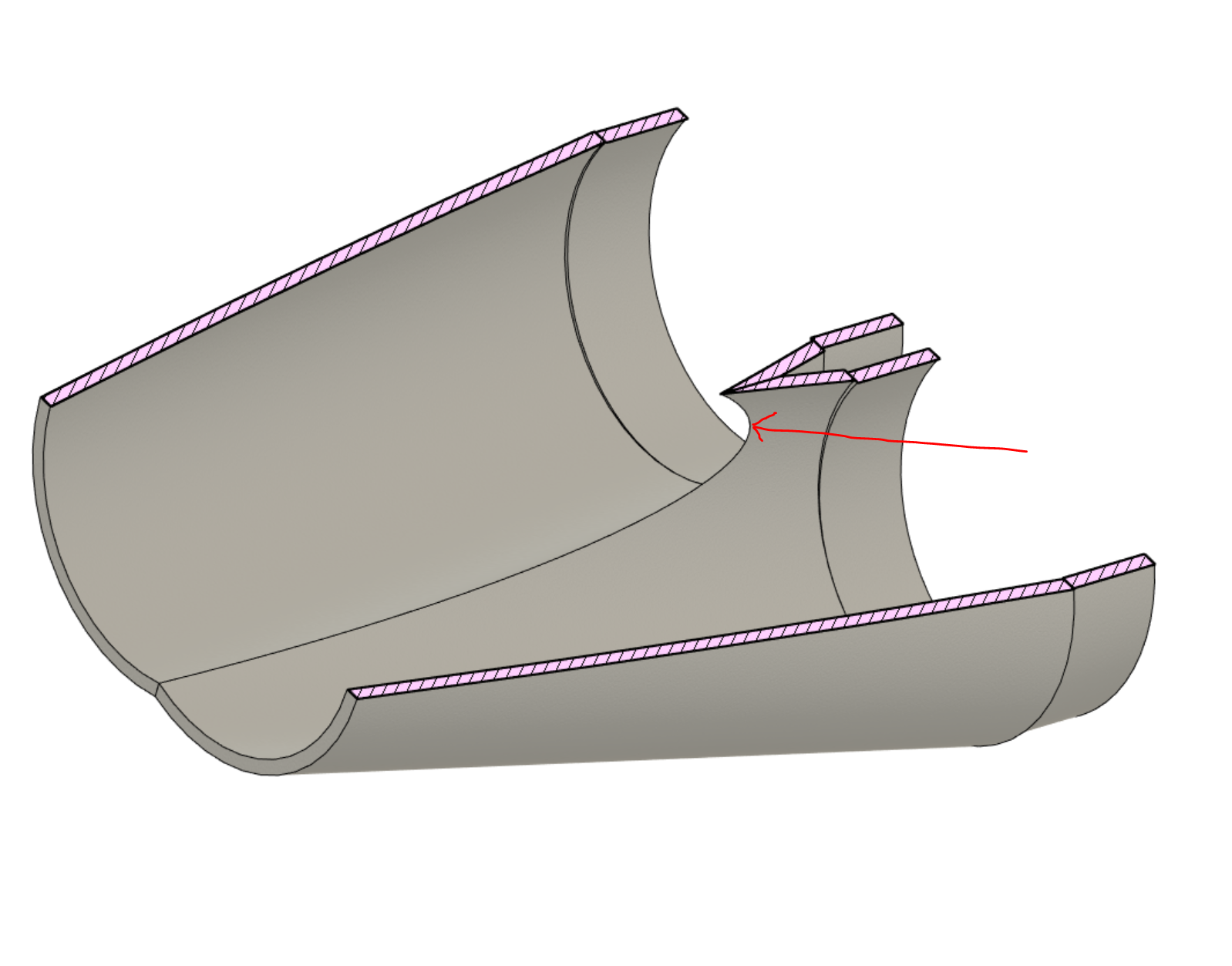
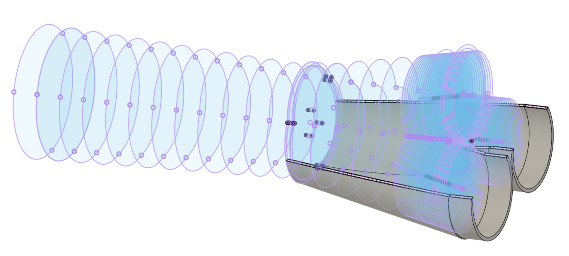
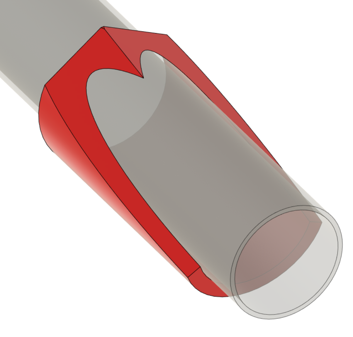
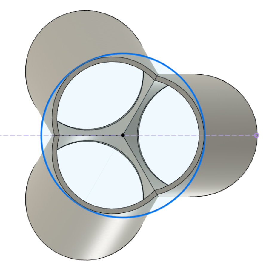
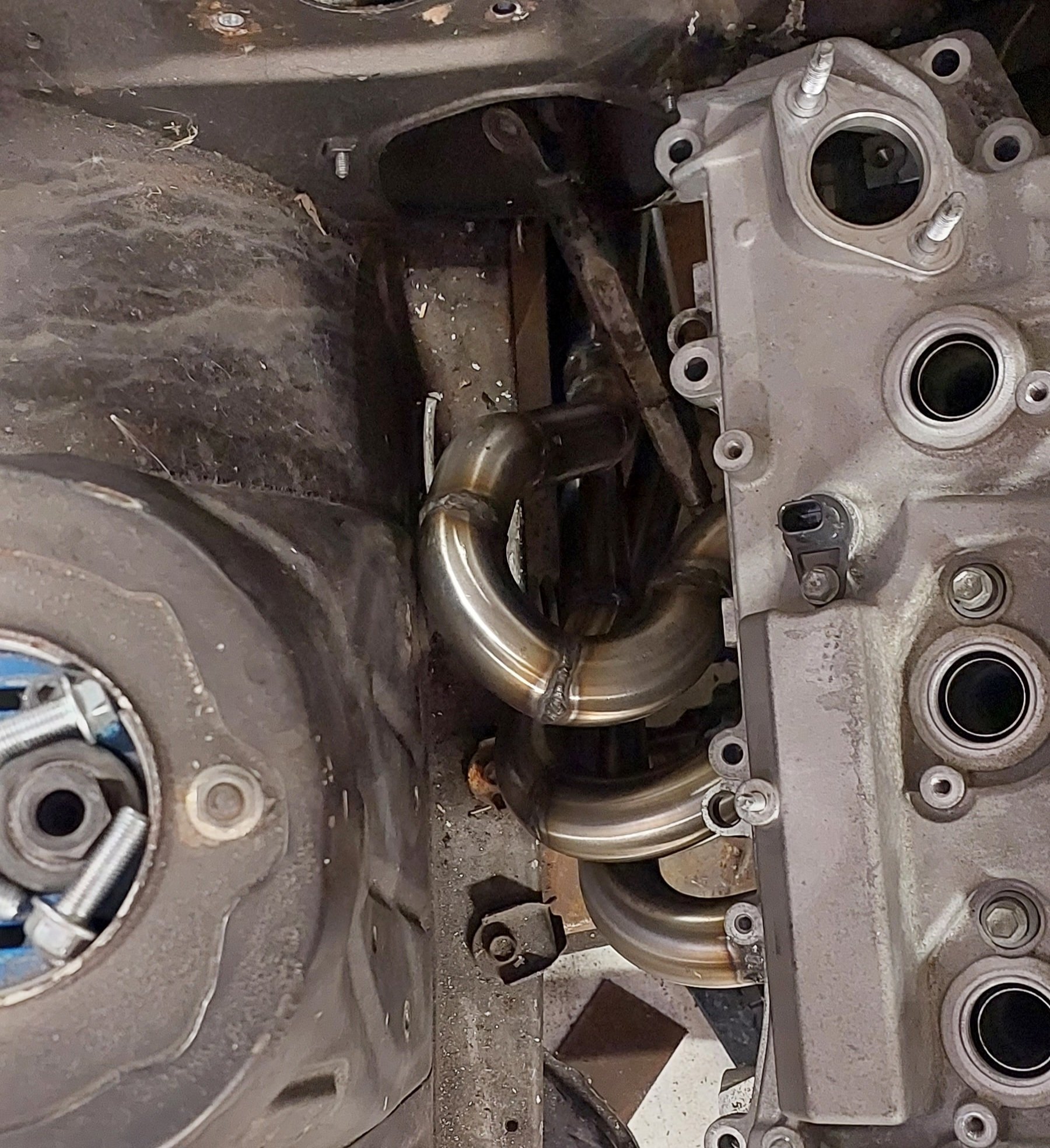
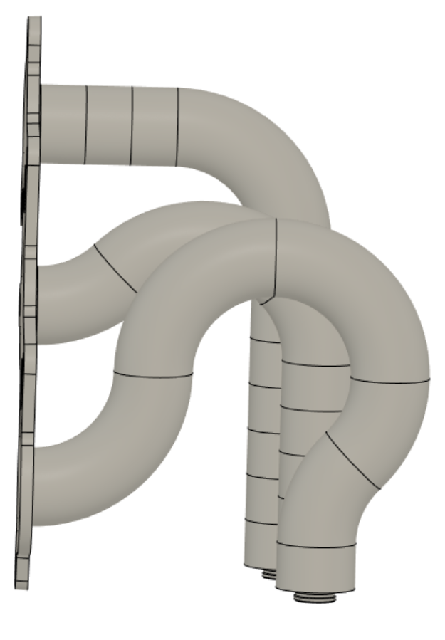
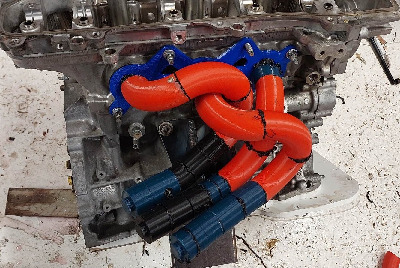
Alright sooooo. It's been a case of: tack pipes. test fit. cut pipes back off. test fit. tack pipes again. scratch head. And so on, for about 30 iterations until I've run out of bends and argon. However I've now got something that clears everything. Doing some checks on lengths, they're within about 40mm of each other. Which is about 5% variation - happy with that. However, a few problems. Firstly, I've chopped and changed everything so much that it's a bit of a mess. Partially due to being short on patience from redoing everything a lot, and not having totally flush surfaces. So welds turned out more pooey than needed. I should invest in a linisher I think. Secondly, This is all great that everything's past the steering column, and 10+ mm clearance to everything. However everything is on some tricky angles to try stuff into a collector. I havent made a collector, because it seems hard. Or I need to buy some. The only purchasable collectors that fit my budget look like baked bean tins that have been stood on. So I will try make something instead. As I think what I really need to do. Is to start the pipes from the collector, then work back towards the head from there. Welding a collector is tricky, because you end up with a bit in the middle that you cant reach to weld when it's together. One way is to cluster the pipes together tight. Then weld a little triangle piece in the middle before it goes together, on the collector and 3 pipes. Then weld the remaining perimeter to finish it. (Idea stolen from @kpr - thank you) So hopefully something like this. To choose where to slice the bottom part, I've drawn a circle the size of a 2" pipe, then just cut it shorter till it roughly matches this. I could go bigger or smaller though I guess? Currently has inside area equivilent to a 1.75" circle. My plan is to print some cutting templates like this. If I had a band saw I'd do it a little differently so the outsides are flat so it sits on the right angle on the table. Actually - yeah might do this and see if I can use bandsaw at dads. Assuming it's happy cutting stainless. Fingers crossed it works out alright. Something else to think about. As per oldschool.co.ng project tradition, 3" exhaust pipe. However - I've got two banks that need to eventually merge into a single 3" pipe. I'm not sure if there's any useful tuned stuff happening in the 2-1 part of a 6-2-1 setup. If I was trying to keep the "secondary" pipes to half the cross sectional area of a 3" pipe, then it's about 2.1" per side. I definitely want to merge all 6 pipes, because otherwise it'll sound like I've got a pair of triumph motorbikes in the engine bay rather than a 6 cyl.
- 81 replies
-
- 24
-

-
Yeah ive had it in and out now a bunch of times while trying to make it fit better. Doesnt need to lift up very high. Probably wont need to on the other side where theres no steering column. I can live with that! Ive now got something that has pretty good clearance everywhere. But ive chopped and changed this a million times so its a bit of a mess. So I might redo it with some fresh bits when funds allow. Has been sort of fun and sort of frustrating. My plan to keep all the runners on a flat plane went right out the window. Just not enough space to the strut tower and chassis rail. I think i will restart with a different approach. Start at the collector end and work back to the motor. These are within 40mm of each other though which is pretty sweet. (So around 5% variation in length)
-
Weerg.com
-
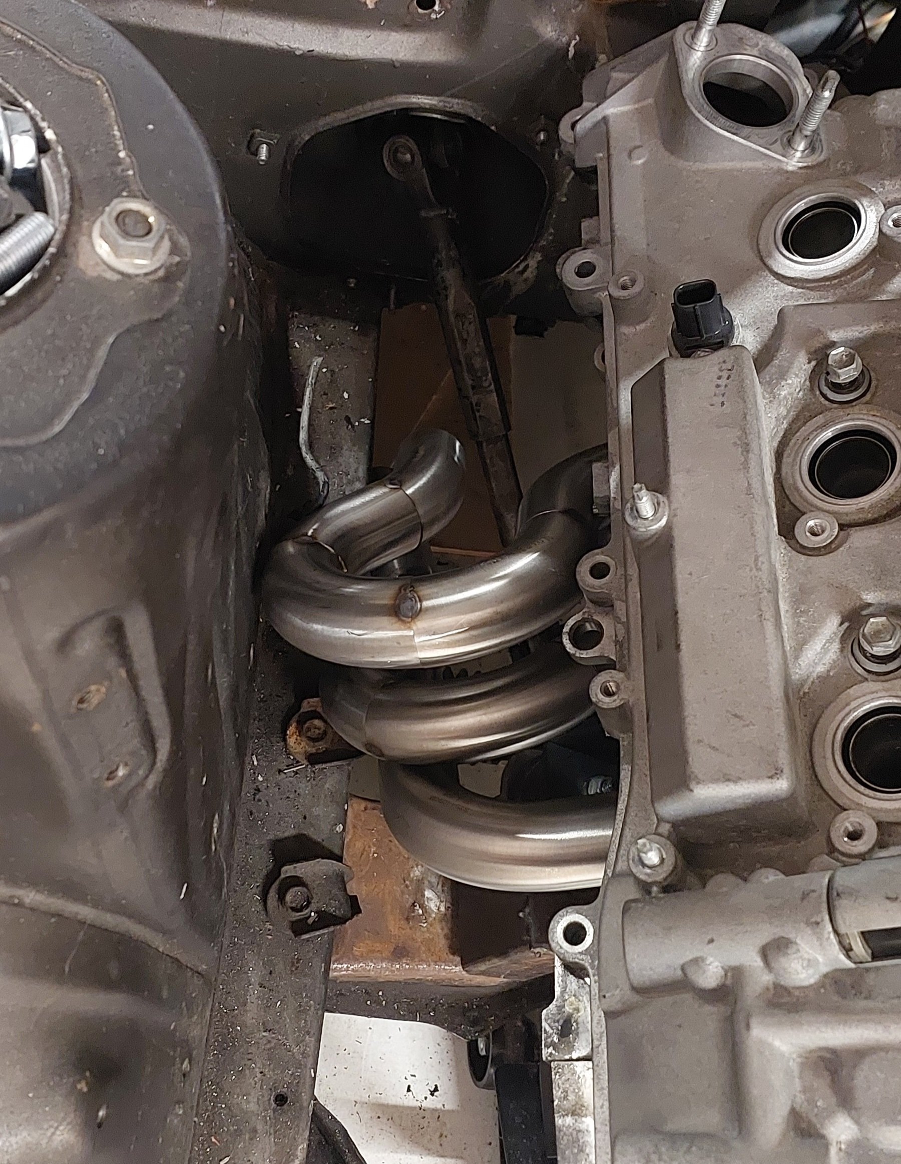
Started pooing together a manifold. Too tight damnit. Will have to tighten the bends a bit with a few angled cuts. Also, the only way I will ever get these off or on is by lifting the motor. And all of the studs in the head need to come out or its impossible. A bit of a hassle but better than having the shitty standard log manifolds.
- 81 replies
-
- 34
-
-
Aircraft people do weird shit with running their engines. My understanding is they adjust the mixture to peak EGT then back it off 10% richer (or something like that) Or some other witchcraft sorta stuff depending on if they are wanting best economy or power when running the motor in steady state slogging its guts out. So in that case the reaction speed of an EGT sensor isnt an issue - they arent really in closed loop. Just using temps to manually trim the fuel. (At least that's my understanding) So for the purposes of what they're doing, ignition timing is essentially fixed. As the motor is at steady state. By contrast the operation of a car engine is absolutely chaotic. With rpm changes, ignition changes, fuel changes happening constantly. Which is probably why they're not commonly used for cars.
-
Out of curiosity, what are you needing to run avgas for?
-
The problem with monitoring EGT is that it's a function of both lean/rich but also ignition timing. If you reduce ignition timing, the motor runs hotter - as less of the combustion force has been spent in the cylinder, more comes out the exhaust instead (as heat and more noise) If you want to run as accurately as possible without closed loop monitoring with a wideband. Then using a MAF as the load source is 100% the way to go. The accuracy of a maf is crazy, through changing conditions without any compensation tables for altitude, temp, etc. (which is why OEM loves them) That's as close as you'll get to closed loop for minimal headaches.
-
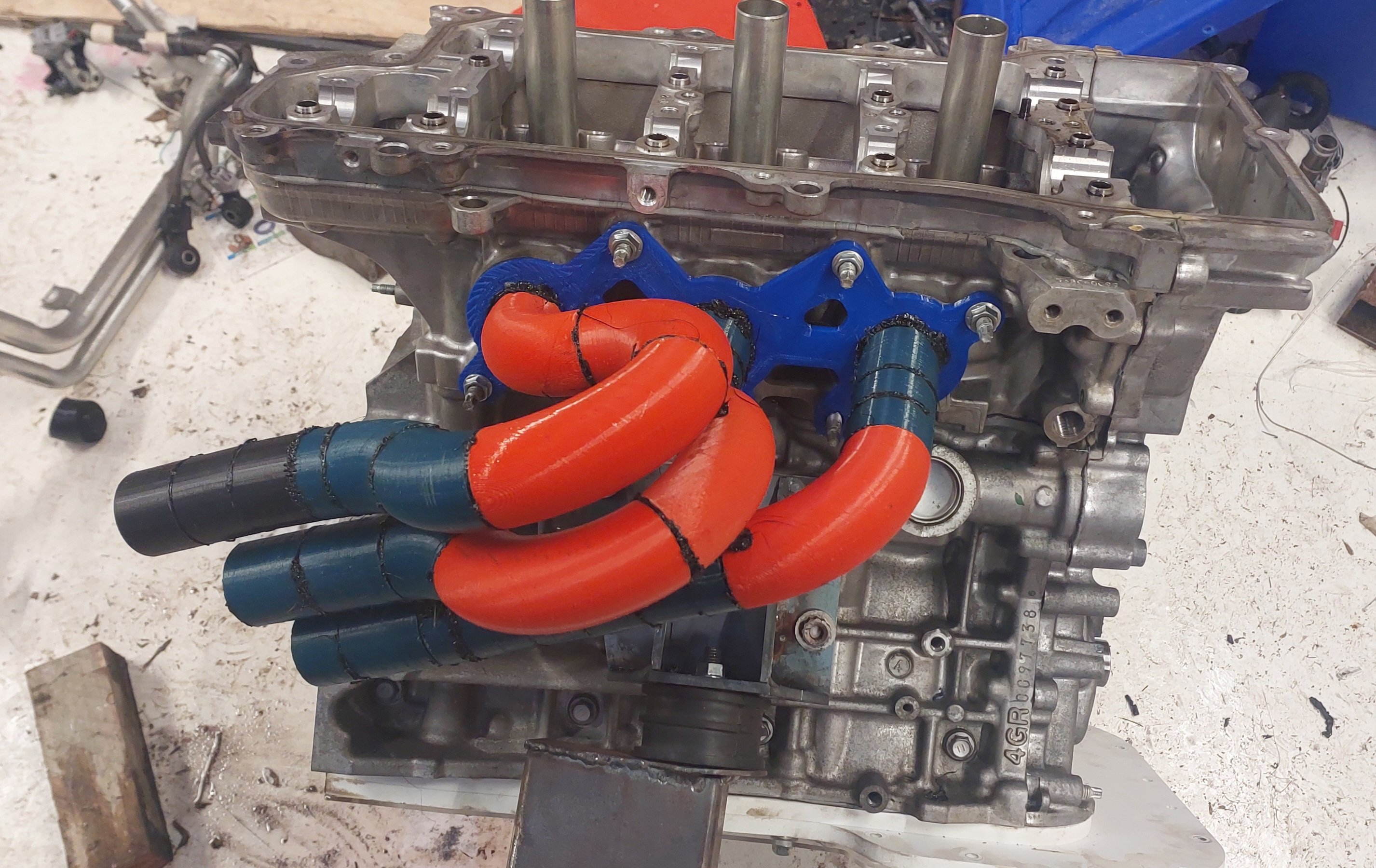
They're PA12 nylon. Ideally would have a radius there, but modelling program was being a dick about it. If it starts to crack there I'll lay carbon sleeve over it like my other ones. However, with an e-throttle manifold and vertically oriented throttles. There's actually very little load on these. The throttles being a single piece ties it all together and add strength. Where as with a cable pull manifold you have to make them really strong, to resist cable force from pedal. Especially like 4AGE throttles where each individual throttle wants to move relative to the next. Each one tries to twist away from the others.
-
$100k USD, give or take...
-
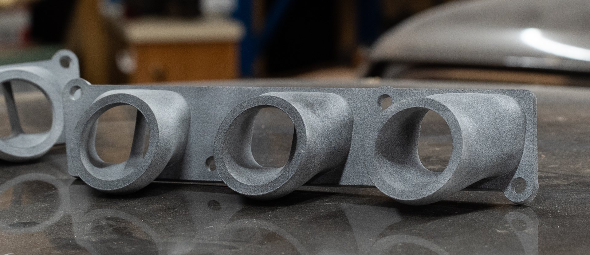
New manifolds turned up, and hooooly hecka they are amazing! No infill, no layer lines - fully solid so they feel really strong. The dividers have a super sharp leading edge on them, and all the details are great. I think from now on, I'll keep using my printer mainly for PLA based prototyping, then will have final parts made this way.
- 81 replies
-
- 47
-
-

-
I think they use the exact same shitty manifolds and gaskets on the rwd 4GR, 3GR, 2GR. So its just massively oversized for 4GR valves and ports. Just absolutely zero effort haha to make it suit the motor haha. So might be some easy gains. Like the echo though, I think the higher the compression ratio the more tolerant it is of a crappy exhaust. I looked at making ports a bit larger, but they seem reasonably decent given the valve size. I'm trying to get all of the basics together first, so it's running. Then that's when the fun part will begin, where I can buy a second motor and try some different porting ideas, try cut down the big divider between intake ports, stuff like that.
-
Its just running the 3d print pen around the perimeter. Makes a satisfying crack when you break it back apart! Can reuse them.
-
For sure, and out of the scope of this project when he's got the Marina to work on as well. I'm just stoked its all running and driving nicely now.
-
A modern ECU would do absolute wonders for this, and would probably pay itself off in about 5 weeks of fuel consumption.
-
That's still incredibly dreadful mileage. haha
-
Much better! Will be fairly easy to get this to work around the steering column i reckon. Fingers crossed. Will probably change the front runner to two 45s spaced apart, so it matches the shape of the rest a bit better. But will order some pipe soonish.
- 81 replies
-
- 31
-
-
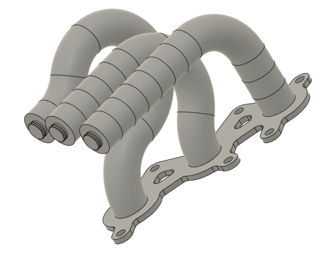
After some IRL lego time. Back to the model to try replicate my best plan, and see how even it is. Answer - not very. I've been trying a few iterations back in the model, just brain storming ways to arrange the pipes that keeps them even lengths. And hopefully doesnt look derpy and is also easy to make. A few non starters... Too complex and also quite ugly. Not sure what to do, so went to google images for some ideas. Decided I need to go back to basics. So make the #1 runner with fewest bends and shortest length possible - then for the others, remove straights and add bends until they're equal. Ha! Works quite well. And each runner is on a flat plane so they're easy to make on the bench. These are within 22mm centerline length of each other. sweet. I hope there's space to make it work.
- 81 replies
-
- 20
-
-
-
With the smaller mounts theres definitely much much much better room for exhaust activities! Before I get too carried away though. I really need to get an alternator mounted on the block, and get the engine mounted in it's final spot. I'm making good progress on those topics but was a relief to see how much more room there is anyway. Will be worth the trouble. It's a tricky job even just with the lego bits, definitely takes some skill and experience to fabricate exhaust manifolds decently! Currently the #1 runner is the trouble child, needs to be longer (Can see that runners #2 and #3 have 3x 90 deg bends, vs only 2) However I cant swing it forward too much because stuff's in the way. Then I also need to make sure that the manifold can physically be removed, but again that's much easier without the giant mounts. The aim is to have a mostly decent plan before I start chopping any expensive bends up.
- 81 replies
-
- 22
-
-
-
The lasercut parts turned up. Holy moly I cant believe how good the finish is! I was expecting raggedy sort of edges but they look amazing. The mounts all just slotted together perfectly, before there's even a single tack weld. This would have been really fiddly without the tabs added. It holds all of the angles etc perfectly. (Another good Idea from Stu - thanks) So, while I was busy congratulating myself, I decided would plug weld the bejesus out of the back of the tabs instead of tack welding them and test fitting... I put the mount on one side together inside out, so the lower bolt holes dont line up. Woops. With some effort I could probably cut the welds back out, but I really did choose the worst place possible to weld them together initially. Since the finish is sooooo nice from the laser cutter, and I'll only make a mess of everything trying to fix it. I'll pay the dumbtax and get the parts for this side recut. Regardless, it feels like I'm making good progress on things at the moment. Dumb to put it together inside out but I'm happy.
- 81 replies
-
- 39
-
-

-
-

-
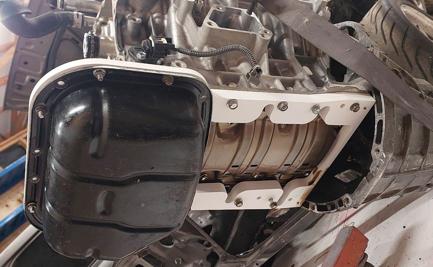
I yanked the motor and box back out, and tried on the sump. Good news is that all of the bolts do up nicely! Test cutting from the foam stuff was a great idea, this is an awesome material for test pieces. Quite rigid but easy to cut with a blade if needed. Which was needed, in a few places to clear the windage tray. So will update my drawings. The total thickness of the sump will need to be a little more than the 20mm. As the clear perspex layer still hits on the windage tray. This might just mean the bottom layer ends up a bit thicker, with some amount dished out to allow for the tray. I'm trying to claw back every possible millimeter here though, so I've got more space up top.
- 81 replies
-
- 38
-
-
-
Far out! Pretty bad about the strut situation. Dodgy even by my standards. The wiring is okay by my standards though. Hopefully you've found the worst of it.