


yoeddynz
-
Posts
17563 -
Joined
-
Last visited
-
Days Won
138
Posts posted by yoeddynz
-
-
-
so many other uses too...

-
 1
1
-
-
-
Yeah what he ^ said. I'm going to be running synthetic oil which seems to stay clearer too.
I am tempted to drill out the cap and fit some tiny momentarily on switched led to light up the tube. But I need to find something suitable to use, like off a keyfob etc.
Keen on links to something suitable. Has to be tiny.
-
 1
1
-
-
- Popular Post
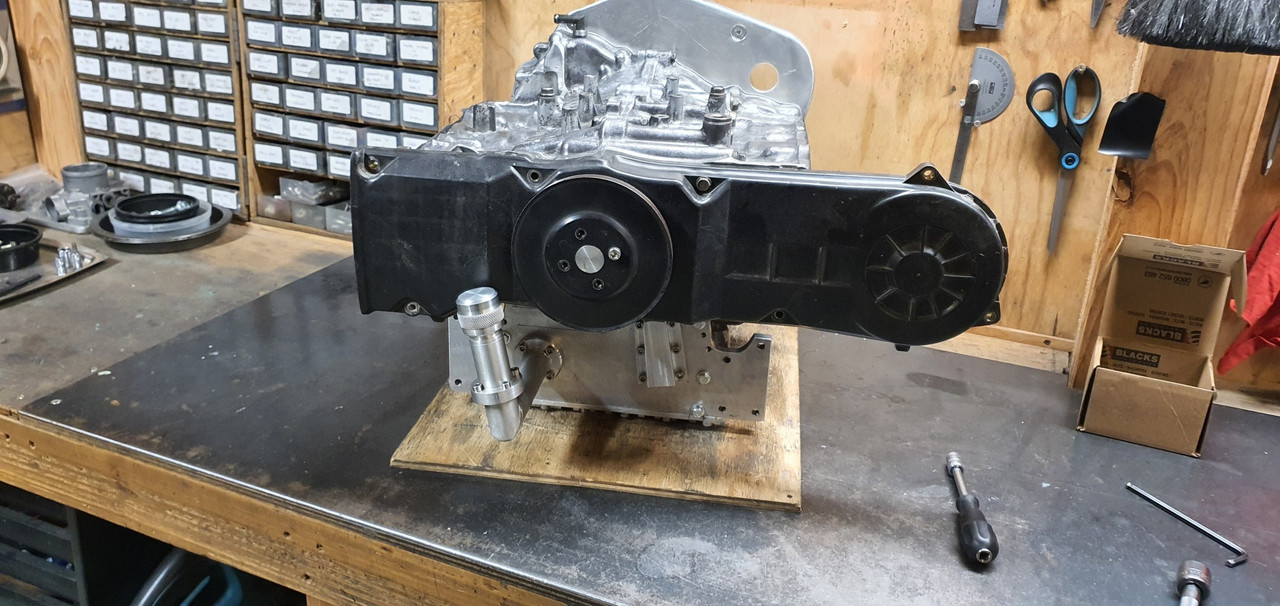
I've not done as much on this project as I'd hoped recently but still chipping away at it.
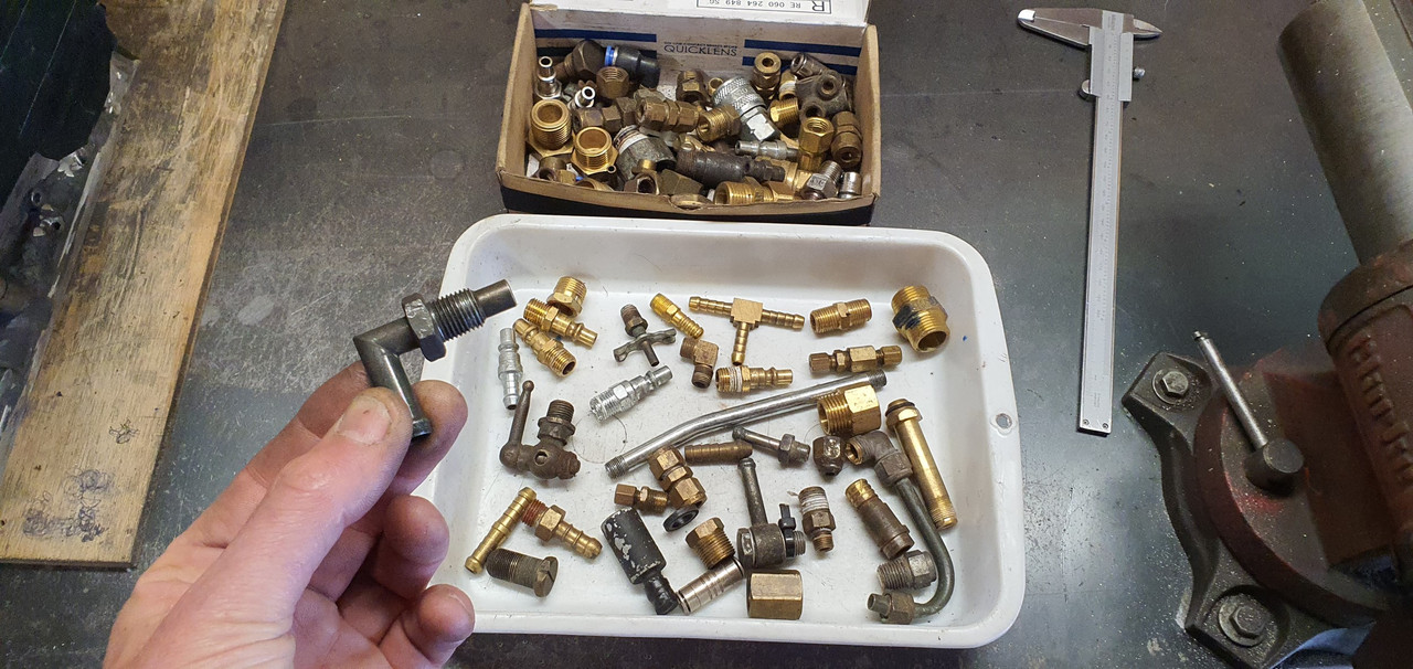
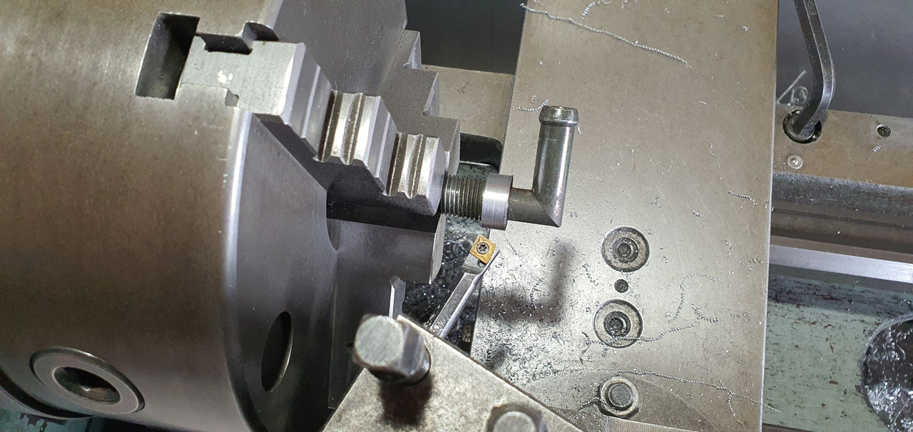
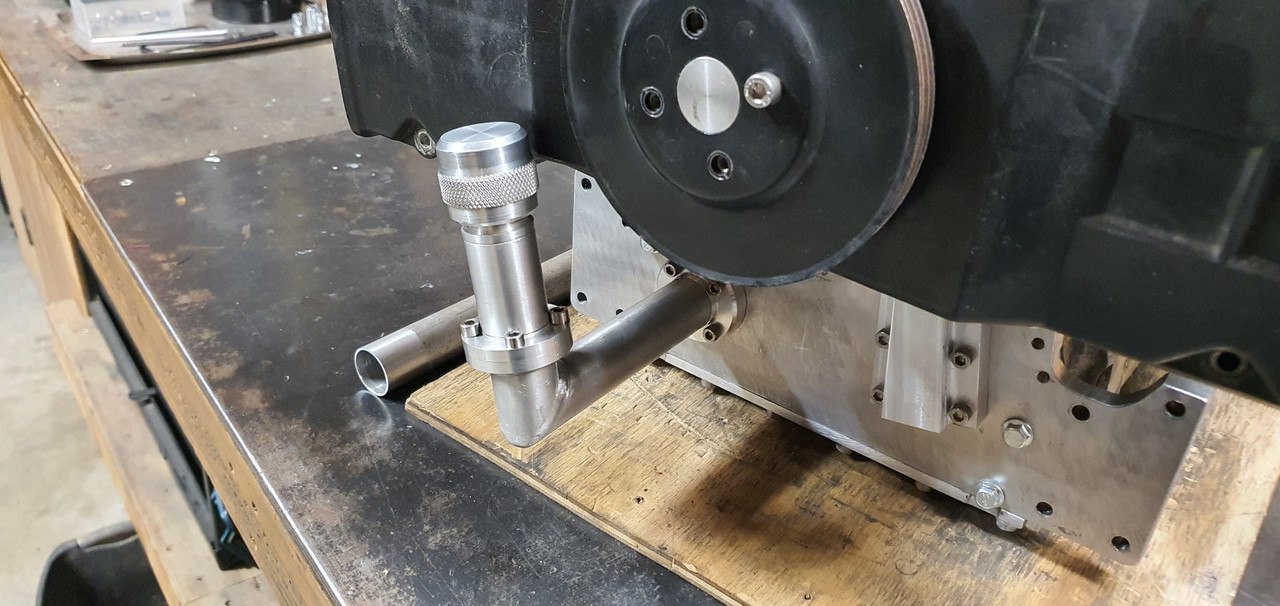
Crankcase ventilation is sorted. I had a rummage through my box of fittings and found a suitable vent pipe thingee...

Into the lathe and with a tiny boring bar I was able to reach in to machine the hub down to a neater size...
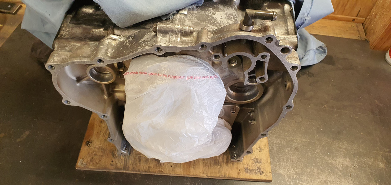
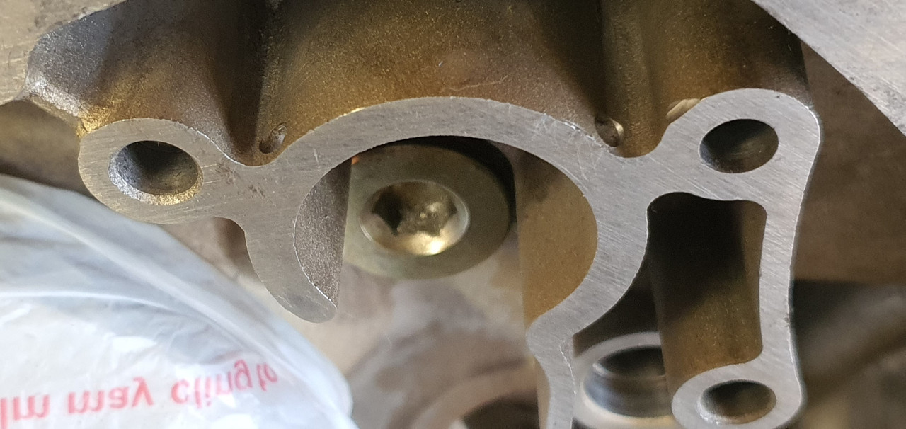
Covered the vital bits to avoid swarf getting in the works then drilled and tapped a hole to suit..
Drilled two drain holes to avoid any build up of of oil accumulating..
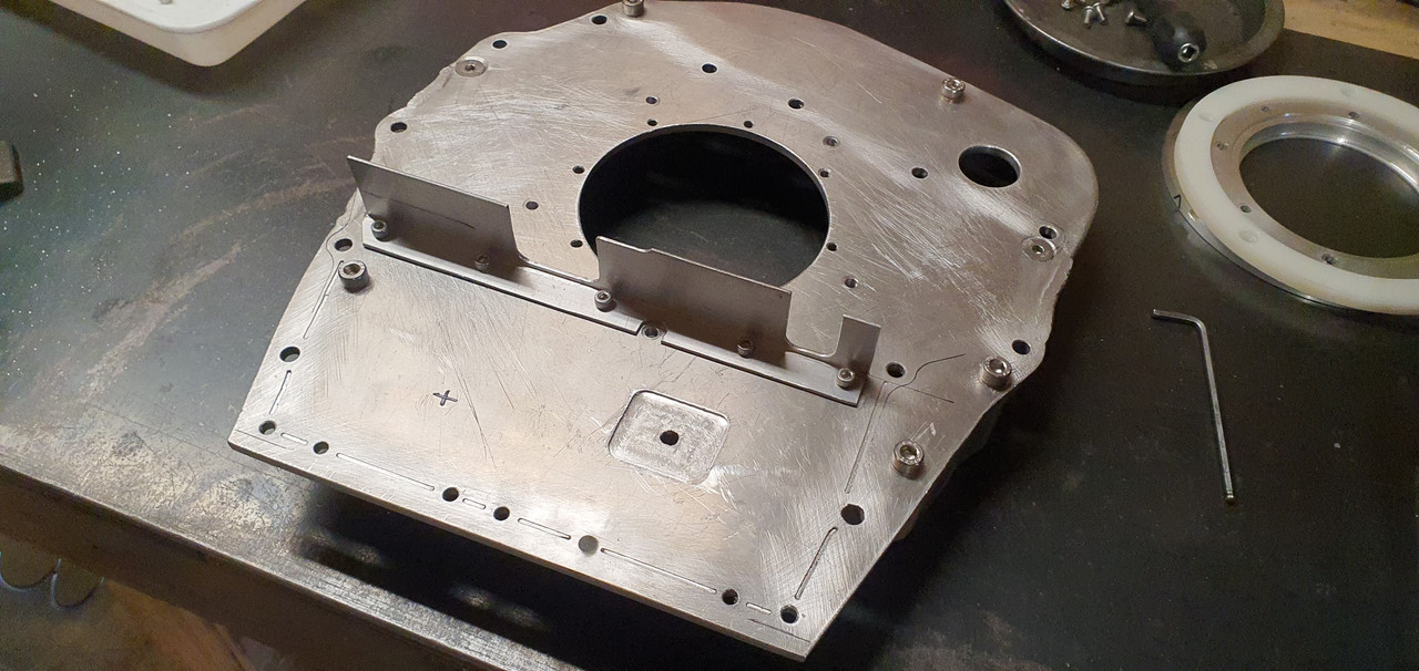
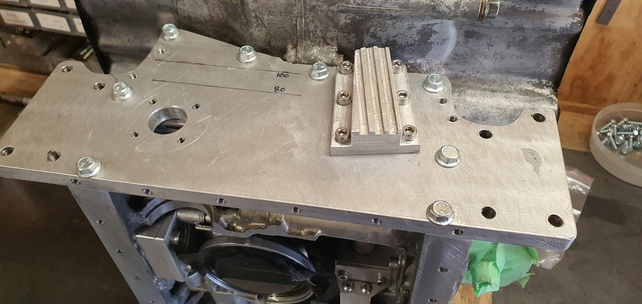
Next jobs in line were to add some extra baffles to help stop oil surge. Remember a while back I had put many bits through a Jenny Craig program in a bid to make them lighter. Well I realised I should have left this plate at its full fat weight and not added this big hole which will let oil surge too easily...
Silly me. Now I had to fill that hole and I was damned if I was going to disassemble all that lot to do it. So machined up a plug, as light as I could but still heavier than the material I had removed in the first place. Oh well..
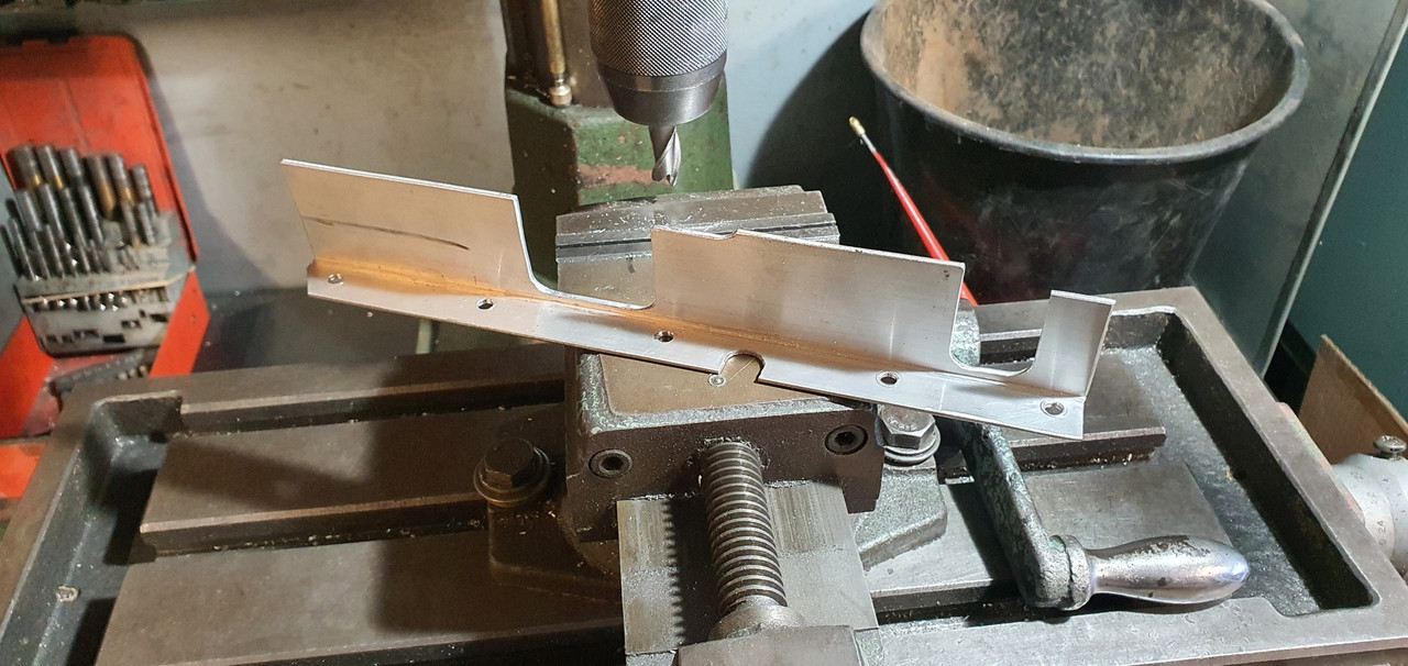
I also wanted to stop oil flowing out of this area under heavy braking so I made another flap. I now have two flaps.
I machined up a bit of alloy angle..
It was bolted here...
In a similar fashion to the 'oil door 3000' its purpose is to help stop oil wafting up the back of the bellhousing plate under heavy braking. Content with the sump baffling situation I could now start sealing and bolting the plates in place. I bolted the backup thrust bearing mount in place on the bell housing and then the bell housing was bolted up to the block..
The thrust bearing was bolted up..
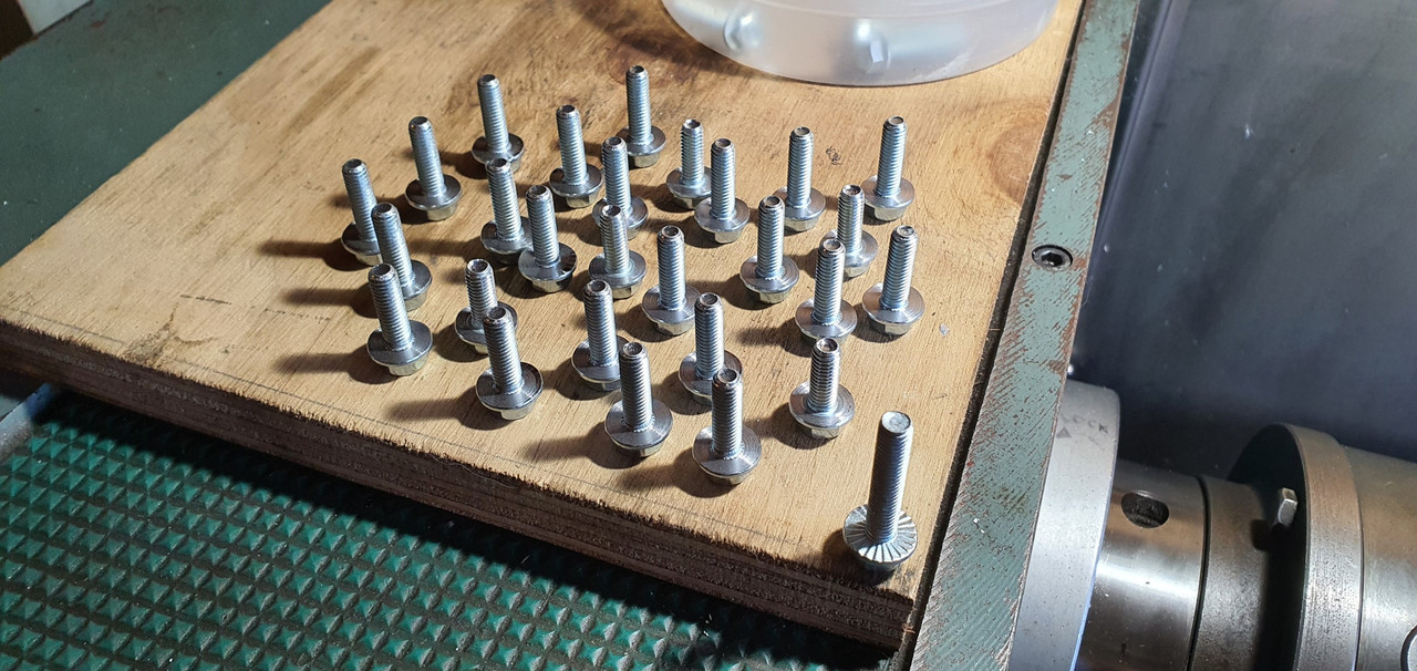
The engine mount plate was then bolted up. I had bought a load of flange bolts for this and the sump but they had serrations under the heads which I had to machine off first..
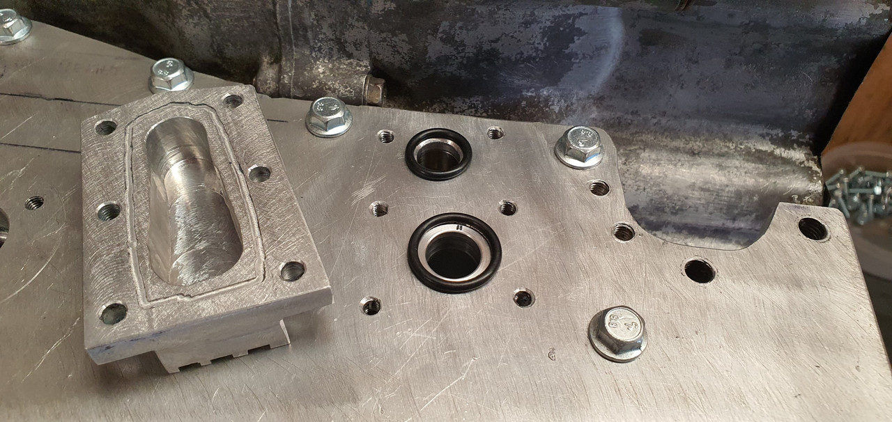
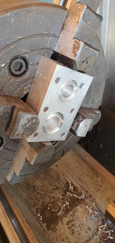
Plate bolted up well. Now to connect the last bit of pipework for the oil system. But I wasn't really happy with my transfer port block sealing arrangement. This thing here...
I had designed it to seal with sealant, held in place with a sealant groove.
But picturing the sealant being squished inwards towards the holes started the paranoid cogs in my brain turning. Yes it forms a nice neat bead and its pretty strong stuff but the thought of possibly having a tiny bit get dislodged in time and finding its way into the oil way to potentially block the crank feed did not impress me. So I decided on a change of design using O rings...
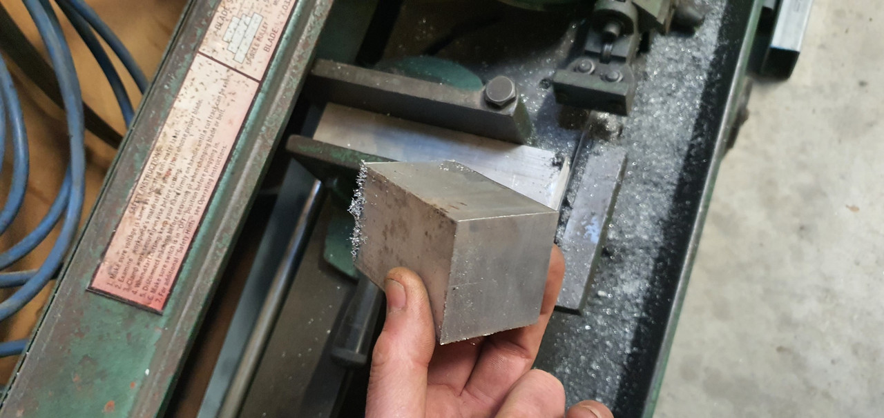
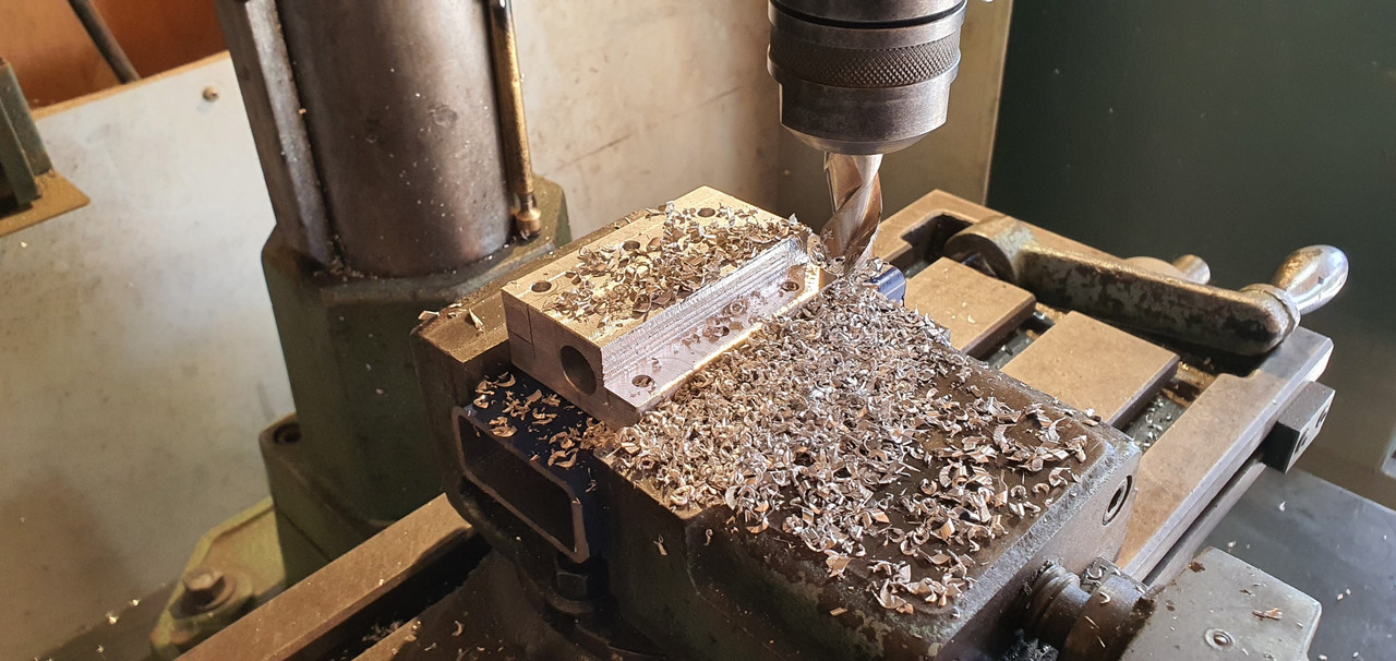
I cut a big lump of alloy off some stock...
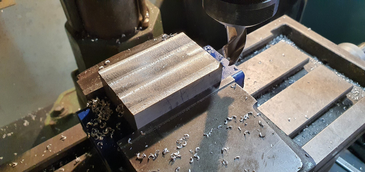
Cut that down and machined it..
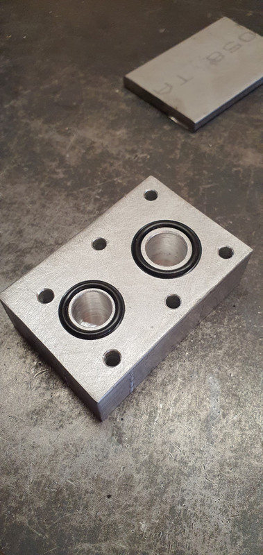
Did some very careful measuring, marking and setting it up in the four jaw chuck so I could machine some oil ways and O ring grooves..
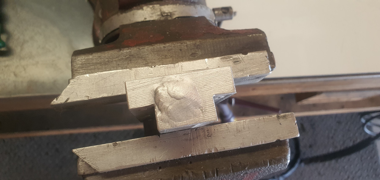
Sealed the end of the transfer port with a plug and welded it in..
Bolted it up and I'm now able to sleep again.
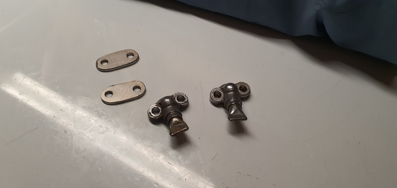
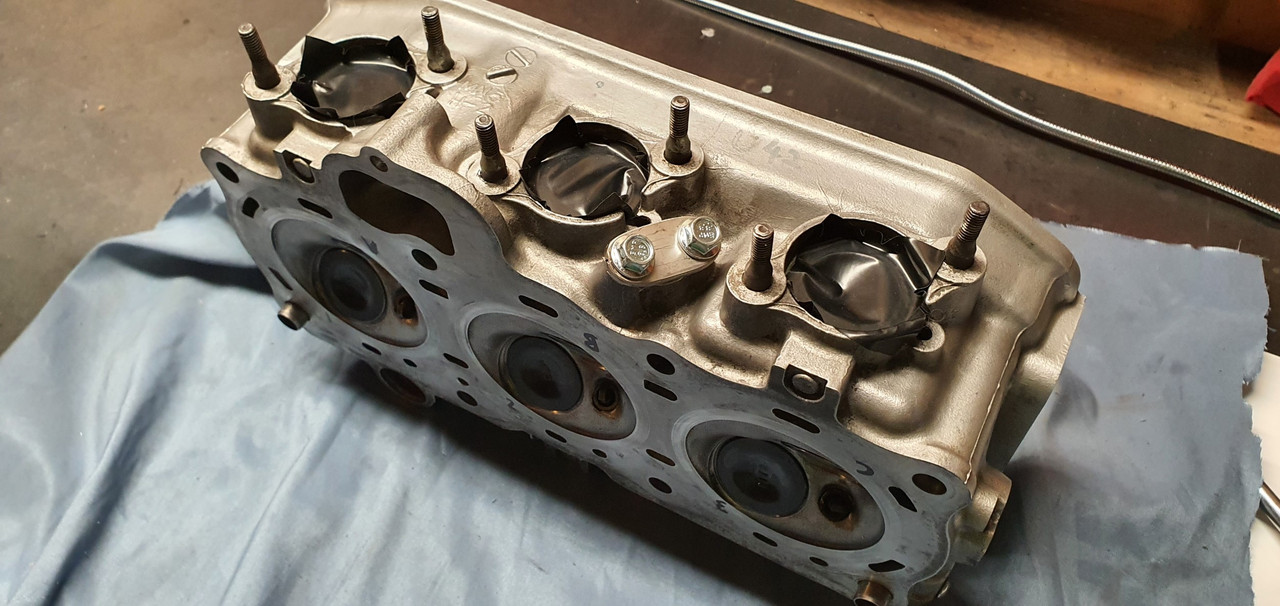
More holes to seal. There were two remaining air injection ports to seal up, one on each head and getting rid of these ugly lumps of metal. I cut and drilled some stainless plate to suit...
Much better.
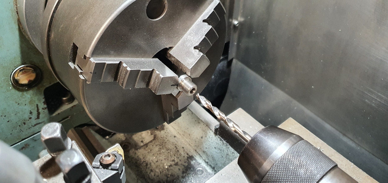
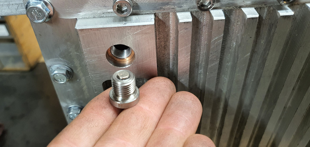
Another little job ticked off was the sump plug magnet. I drilled into the stainless plug just deep enough to fit a very powerful tiny magnet I'd found on a keyfob thing..
Epoxied in place..
Continuing on with all things oil I shortened the oil filler neck to a height I was happy with.
I'm now trying to decide on how best to possibly add a little sight window into the tube. The flange I had made to allow the filler neck to be removed so the cambelt cover can be removed easier is possibly not needed any more with the neck being so short. The planned oil level is also at or just above the flange join thereabouts. I'm going to have a think about this aspect a little more before I commit to final epoxying of the bits together. Luckily its all easily unbolted so I can be changed anytime in the future anyway.
-
51
-
 1
1
-
- Popular Post
- Popular Post
Nelson Arbath. Owner can be seen sitting in sun, having a beer and admiring his little car
")
-
17
-
A message I just got from hannahs brother in London village..
"I cycled past a k11 si yesterday, didn’t have phone on me so no pic sadly but I’ll describe it’s incredible beauty… dark slightly shiny/pearlescent green, 3 door, blacked out rear windows and boot, spoiler on roof at back, little spotlights either side at the front but low down, below the other lights. Very lovely! being driven extremely slowly by an old chap who looked about 90. Probably owned it from new. Dream car!"
-
3
-
3
-
-
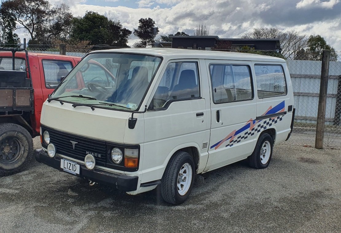
Crap pics I know but as slow as an XJS is I couldn't quite catch it in our mighty 50 series hiace..

-
7
-
1
-
-
^ facelift, lifted and on its face.
-
1
-
-
This van is looking so sweet!
I think you need to raise the back up, not lower the front..
")
-
2 hours ago, dmulally said:
Question: why was I even born
It was all going so simply when you just had the one imp with a plan in mind.
I'm happy to relieve you of the burden and take the van off your hands. I'm nice like that.
-
1
-
-
-
Thanks so much man. I'm hoping it all works out ok for your amusement and my sanity.
-
2
-
1
-
-
-
I
6 hours ago, TimShadboltfan27 said:Josh Coppins old MX van. one of my earliest core memories is that thing loaded with two RM125s in the late 90s at the Rat Track.
/ling
It's still his van. He's owned it for yonks. I think it's in for some work.
-
1
-
-
- Popular Post
- Popular Post
Very tidy 50 series. I want those round headlights and grill etc to match.
-
11
-
Ditto what he ^ said. It's looking amazing and you're continuing to do such a neat, well thought out resto. Congrats on first drive in 6 years. I bet that felt great!
-
1
-
-
8 hours ago, brocky41 said:
Dont know if posted but how cool would a wagon or 'Box' be? Surely a few imports have come in
A lot more useful. Its pretty tricky trying to get two bikes into a standard hatch.
But yeah - they ain't pretty.
-
@ajg193 here...
Its a two wire type (so always closed by a spring unless activated) which is like the type I used to good success in my Viva (a mazda type)
I was thinking of getting a 3 wire but for what I need to do, the two wire type are so simple and reliable.
Plug is a bosch (?) type one...
-
1
-
-
On 31/08/2023 at 21:15, Alfashark said:
S21 by the looks.
Fuck that sounds lush. What's the deal with the gearbox. Is it a pre-selector or does it have air operated 2 speed axles? He changes gear without touching the gearstick at times.
-
I personally think your induction system just needs more mandolorians.
-
3
-
2
-
-
Cough cough @ProZac don't be shy
-
2
-
-
- Popular Post
- Popular Post
On 02/09/2023 at 23:42, cletus said:
I was lucky enough to drool all over this, the sole road going version I think, at a rotary meet in the UK. It had been re-powered with a Mazda 12A iirc. I took one pic (my rx3 in the background)
-
9
-
2
-
- Popular Post
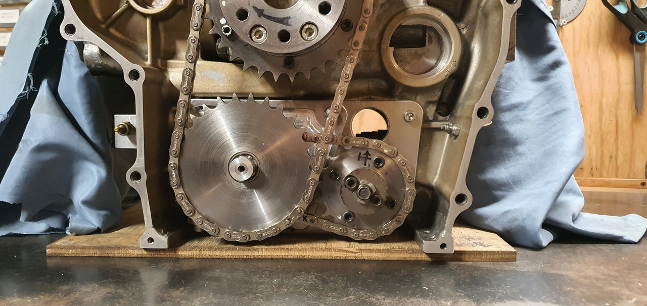
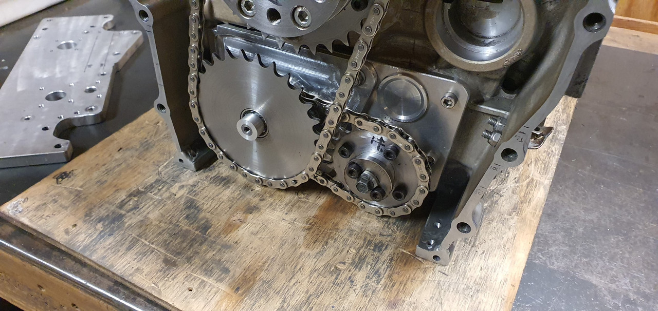
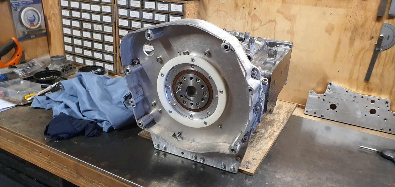
So last time I popped by I was talking about my ring piece. I machined it to suit the location around the rear main seal holder, then cut out another ring piece from the engineering plastic. Harder to cut with the jigsaw than I expected. Put it in the lathe, machined it to the same size as the alloy ring. Machines really nicely. Makes lots of fine mess, much like a very not so tasty candy floss.
I then drilled and tapped the alloy ring concentric to the main seal holder on the bell housing backplate. Then drilled the plastic ring, spot facing the holes and bolted it to the alloy ring. I now had an easily replaceable large thrust bearing.
Next was the tricky bit. The crank has about .007" lineal movement on the crank. I wanted to set the thickness of the ring just so there's a smidge less because it will bed in. First I had to get close enough I could start accurately measuring it but I couldn't get in between the backplate and the flywheel to measure in any accurate way. So I used some plastigauge between the flywheel and its hub. Id fit it in place carefully and because the plastic was slightly too thick the plastigauge would show me how much I needed to remove from the thrust face before there was no lineal movement at all when the flywheel bolts were cinched up.
Once I was at that point I could take a skim off the plastic and I ended up with about 5-6 thou movement. Perfect.
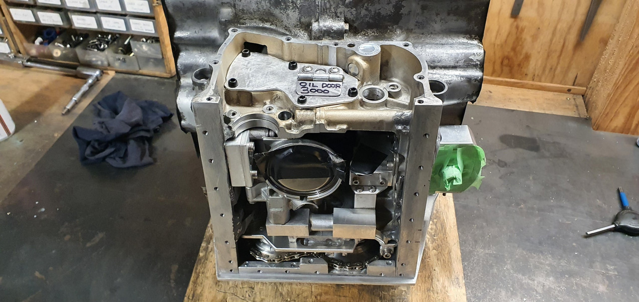
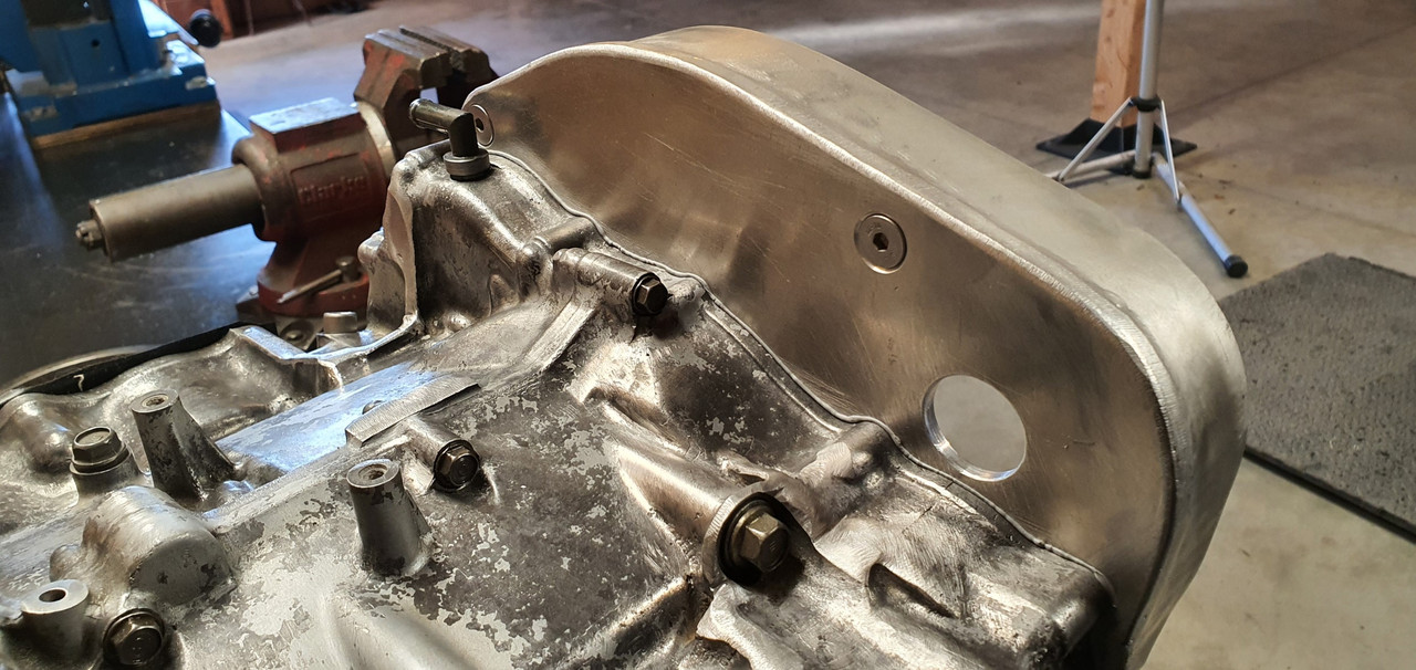
Because its an English car, irrespective of what engine is fitted it'll no doubt leak. So in order to help it drip oil properly I added a tiny drain hole below the rear main seal..
...and a hole in the bottom of the bellhousing. Always horrible having a build up of oil in a bellhousing, flicking all over the clutch etc. Now it can leak gracefully onto a drip tray
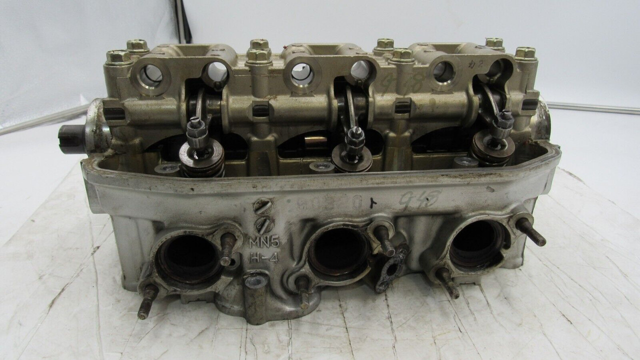
I put the dust sheet over the block and pulled the cylinder heads out from under the bench. Gave them both a clean as best I could with the valves in place. A nice job to relax into in the afternoon sun...
Heads much cleaner I put one aside and set up shop on the bench to remove the valves and clean them up. I was going to put the bits in an egg tray but it wasn't really ideal so instead a plastic tray with moveable partitions. Very careful not to mix any bits..
The seats and valves were all really good. A bit of carbon build up behind the heads on the exhaust valves but they all cleaned up mint in the lathe with a wire brush. The stems had barely any sign of wear and were jiggle free in the guides. More signs that this engine really is a low mileage, well maintained unit.
I made a basic wooden jig to hold the heads at the valve angle so making for an easy time to accurately lap the valve seats clean. They came up sweet with minimal lapping.
Happy that the valves and seats were good I decided to give the ports a little clean up. Nothing too flash but there's a few casting ridges etc that I could remove...
I was going to use the air grinder but the Dremel seemed a lot more suitable, especially when I remembered I had the flexible extension I've never used before. Wow!! Its perfect for the job.
Just a tickle..
Into the sunshine and swapped over to some tiny sanding drums to smooth things up.
I wanted a nice clean but 'rough' finish on the inlet ports. Certainly not polished. The exhaust ports were smoothed off a lot more but not polished either, a waste of time for very minimal gains on one of these mildly tuned engines I think. If this engine swap works out well, without grenading the transmission etc then another set of heads will be a fun thing to play with. More on this later..
once the port clean up was completed I fastidiously cleaned the heads and blew away any signs of anything that might cause harm if it were to get into a bearing surface. Brake cleaner and the airline was perfect for this.
Next I sealed up the ports and fitted the plugs back in place..
Brand new stem seals, the ones I'd ordered from Norway of all places and they had taken bloody ages to get here, but here they are..
Refitted the valves and called it done. Rise and repeat for the other head. Then I had two nice clean heads ready for service..
Next job was the cam follower assemblies. Again, like the heads, not too dirty, no real signs of oil staining etc but certainly in need of a clean anyway.
The underside showing the rockers..
Plastic tray compartments cleaned and shuffled about to suit their new role. One assembly at a time.
The rockers, followers and rocker shafts show next to no wear. The lack of needle roller bearings between the rocker and the eccentric lash adjuster cam thing dates this engine to something around early 90s. If I'm correct I think they added needle bearings around 1993.
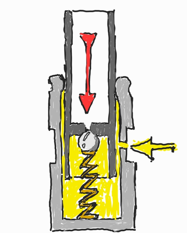
Here's a pic to show how the hydraulic lash adjuster moves the cam and so take up the slack in the rocker..
These adjusters are like many you might find in car engines. To make things easier to explain here is an exceptionally accurate, highly detail and finely drawn technical drawing I just did on my phone...
Oil is contained with the the unit and held under pressure by the engines oil system, fed to each adjuster by oilways within the cam follower cradle. The piston part, uppermost, is a very fine fit into the base and held in place by crimping. In order for them to work properly the air must be removed from the adjusters and that's what the spring loaded steel ball is for. Push that in (red arrow) and air is expelled. If they were to be left on their side or upside down the oil within will eventually drain out and air introduced.
From what I can work out they don't self bled and the oil within is not constantly renewed. So over time the oil will break down and become dirty just from the minute amount of metal on metal wear within. Mine certainly showed as much as I cleaned them out and they took a good bit of working before they stopped showing any wisps of dirty oil. There is a special Honda tool that is used to push the ball valve in. I machined one up in aluminium with a bit of tig rod set in the middle but in use it wasn't as good as just using a neatly shaped bit of 1.6mm tig rod. Using this I was really able to see what was coming out each time I purged them after draining.
As per the manuals I used kerosene. I had three little vessels filled. Then, after they had been left upside down to drain any residue left over I re-bled them using Penrite fully synthetic full zinc bike oil. I figure that since the oil in these adjusters might never get changed out it makes sense to have some decent oil with good anti wear additives... plus I happened to have a container of it because I use it in our Honda big red quad bike
The adjusters were now all clean, lubed and showing no movement when pressed, which is what is required when bled. I then cleaned the rest of the parts and reassembled. I mounted them on the wall facing up - ready for when I need to fit them to the heads.
Interestingly whilst doing some googling on these units I discovered that the Honda Valkyrie 1500, a sort of sportier cruiser version of the touring goldwings, has apparently got slightly hotter cams. I have not found any definitive info on exactly what the difference is. More lift or duration etc.
But more interesting is that they also ditch the hydraulic lash adjusters and instead use simple screw and nut type adjusters on the rockers as per many other Honda bikes. See here...
So my future plan if this engine setup works out ok would be to locate a pair of Valkyrie heads/cams/followers and have a play with them. At the same time I could setup these BMW itbs that hannah so kindly brought back from the UK ...
They'll need the tabs lengthening so to space them apart a touch further to suit..
Other parts, this time delivered by the postman...
Bosch style (but not price) Idle air control valve, various sensor plugs and some shiny new exhaust gasket rings and nuts.
So the heads are ready to go back on but before I do I wanted to sort some other little jobs out while the engine is compact and easy to move on the bench. This morning I made this...
It's designed to stop oil surging back up the filler tube. It really is probably not needed actually bu I see no harm it being there as a belt and braces add on. I'e still yet to decide on the final height and extension of the filler..
Oil height and volume is going to be more than sufficient I think. I'm not sure what the height was in the original configuration and I seem to have foolishly thrown away the original dipstick so I cant check that. Dipstick went in here..
I'd like to have the oil height maybe an inch below the crank throw. I'll have a think about this. Anyway - lots of room for oil. I think about 4 litres at least.
I also need to add a vent to the crankcase. Most likely it will be here, right below where the little owl is sitting...
Because there is a useful casting that would shield the vent hole from oil splash..
-
47
-
1

.jpg.6dfb2ede42654da7eef39b5ee3acf04f.jpg)


.jpg)
.jpg)
.jpg)
.jpg)
.jpg)
.jpg)
.jpg)
.jpg)
.jpg)
.jpg)
.jpg)
.jpg)
.jpg)
.jpg)
.jpg)
.jpg)
.jpg)
.jpg)
.jpg)
.jpg)
.jpg)
.jpg)
.jpg)
.jpg)
.jpg)
.jpg)
.jpg)
.jpg)
.jpg)
.jpg)
.jpg)
.jpg)
.jpg)
.jpg)
.jpg)
.jpg)
.jpg)
1/24 kitset models
in Other Projects
Posted
@Indiana_Jones how much did you score the tamiya spray setup for? I'm keen on one, not just for models but also little jobs in workshop. I figure there's possibly clones available on aliexpress but not yet looked.