Themi
-
Posts
73 -
Joined
-
Last visited
Everything posted by Themi
-

Random slightly cool stuff you built but not worth its own thread, thread
Themi replied to h4nd's topic in Other Projects
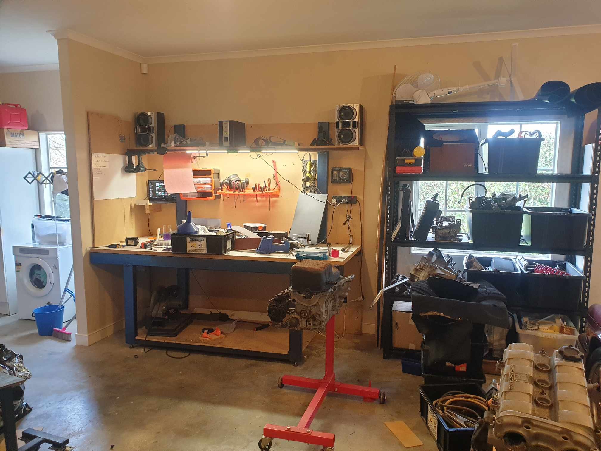
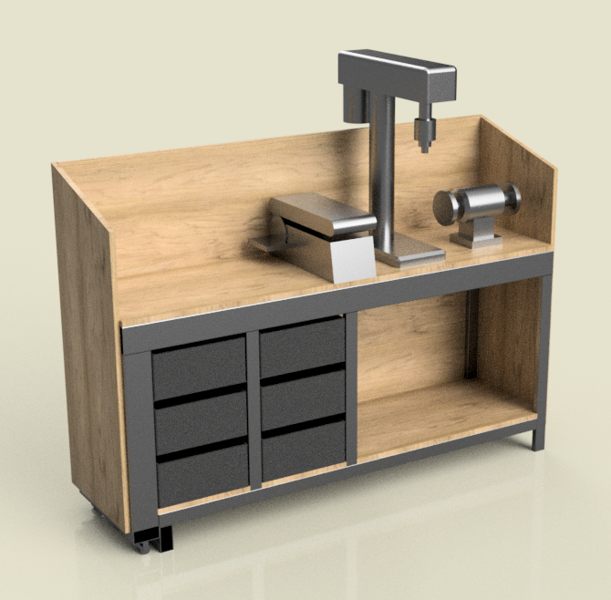
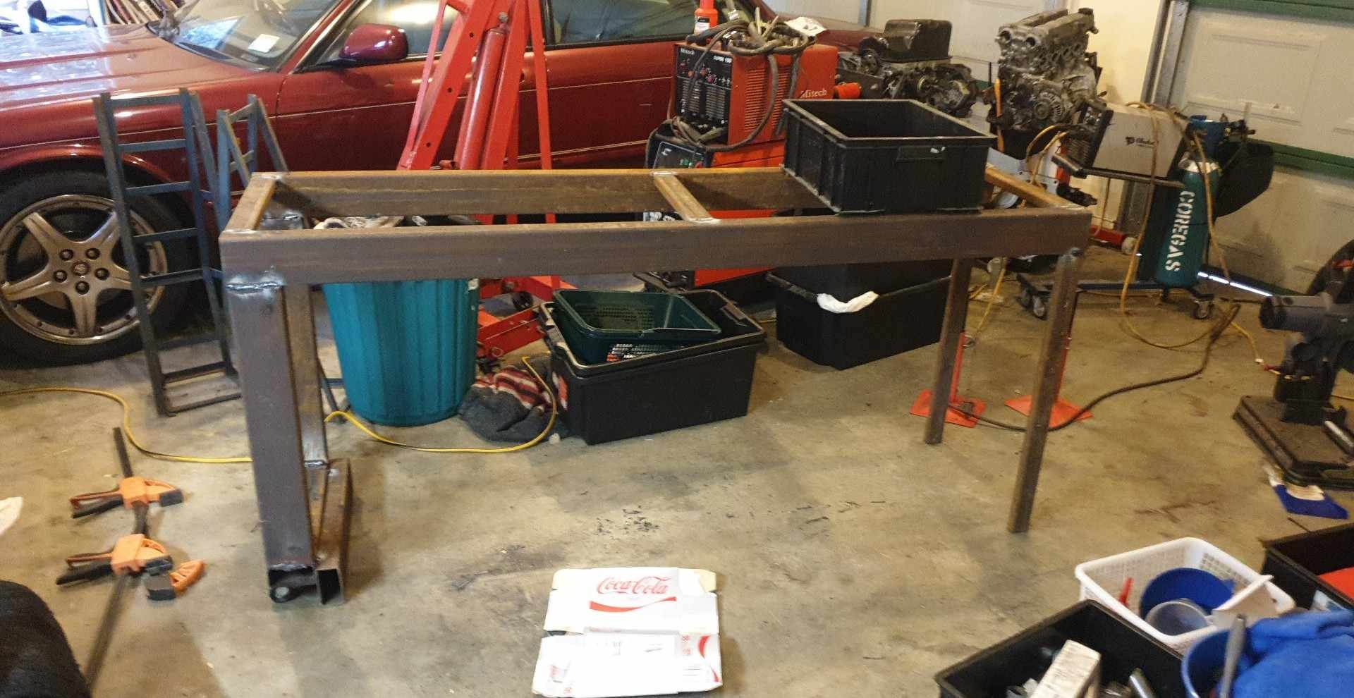
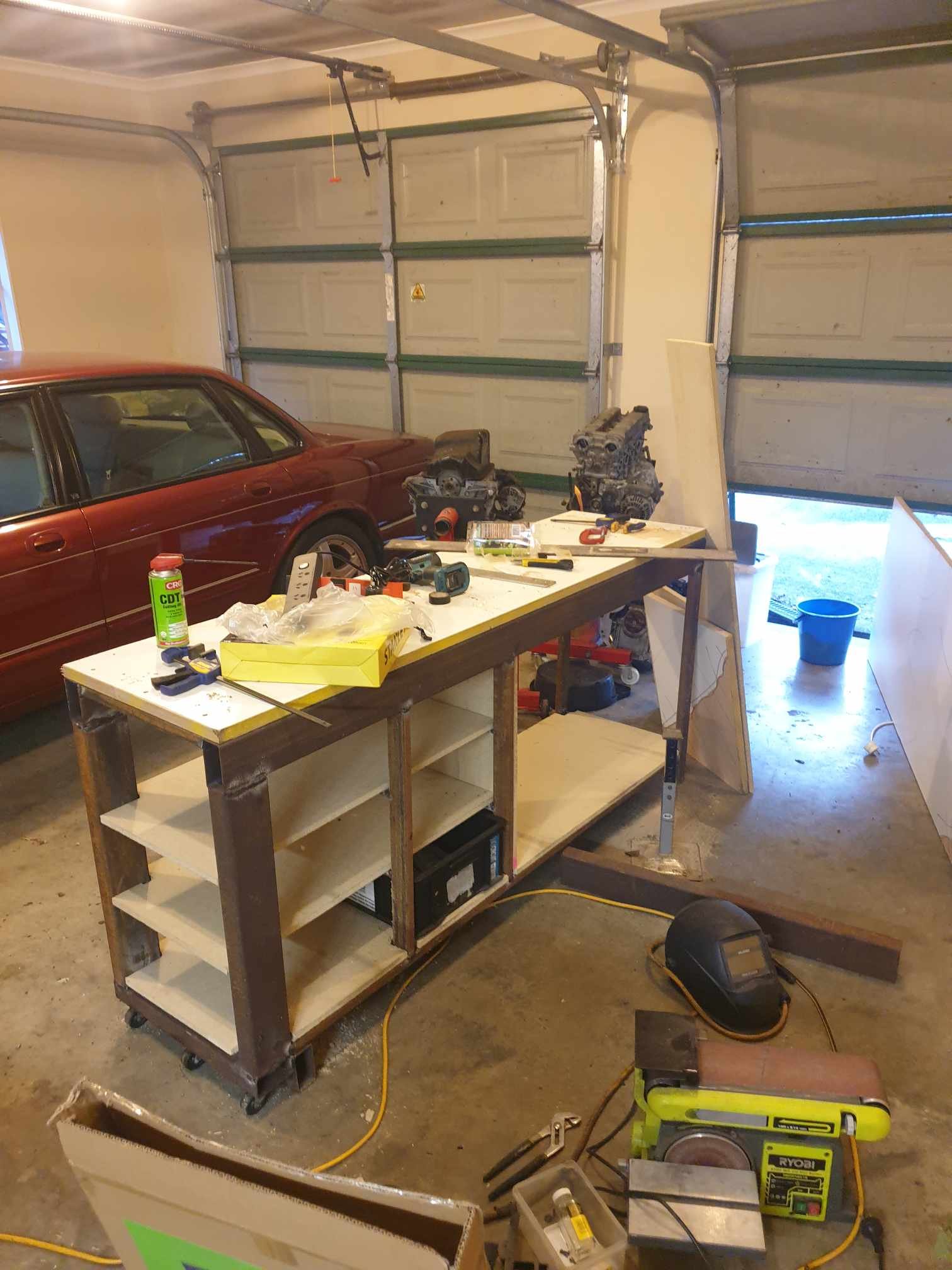
Background: I built my first workbench a few years ago, mostly 100x50x3mm box section, quite a bit of surface rust (was cheap as chips) and used MDF for backing and some melamine coated MDF for the bench itself (total 36mm). It has been good, but it can be hard to do everything on one bench. This was just when I moved it to its current home, before it got swamped in all of the things behind me when I took this picture... I was sick of not being able to use grinders/sanders until I had tidied the clean stuff off the bench, and I was sick of my "clean" project stuff becoming "dirty" project stuff when I inevitably used grinders and sanders without tidying up the bench first. So I needed a new bench. Goals: House drill press, bench grinder, bench sander, air compressor and the vice. "Shelves" for some smaller plastic trays I had lying around. Materials I either have or can get easily Wheels on one side so I can raise it with the jack and move it out of the way. (added later) A small "lid" that stops die grinder swarf and bench grinder dust from covering the other car in the garage. Build: It starts with a plan, so I measured everything I wanted to have fit and made some loose 3d models to see how it would all come together. I won't swamp the post with fusion renders, so heres one showing approximately what I was going for. On the bottom left you can see I had cooked something up using some box section steel as a "foot", with some wheels just on the outside of the foot. The bench normally sits on the solid foot, but when you barely lift the right hand side, the bench comes up entirely on fixed wheels. Started with a rough frame (very rough welding... stick isn't my forte and I'm not wasting a bunch of time cleaning the rust off! Added the rest of the structure, shelves notched with a skilsaw and a hammer... Benchtop is 25mm ply with melamine coating, heavy stuff! Result is a pretty decent attempt at a dedicated grinding bench! Discussion: This bench remains covered in dust and swarf, but the primary bench can have long-term electrical or welding projects hang out without getting completely filthy. This bench also can be moved by one person lifting up the right side (kind of heavy with all of the tools+air compressor), but the low profile jack can get under it and lift it too, making it quite maneuverable. If I had to do it again, I would: Not buy the cheapest possible ($5/sheet) non-structural MDF cover for the shelves and backing, it really is crap to work with, and I'm certain I'll have to re-do most of it as soon as someone even sweats near it. Measure twice, weld once. Quite a bit of the structure isn't perfectly square, which is mostly fine for a workbench but its kind of problematic for the shelves, backing and sides to all line up. Make it full height with a proper lid, and provisions for lighting. For now I've jerry rigged a portable worklight as the main lamp, but the shadows are too harsh. Provision some sort of handle on the "picking up" side. It has no good way to grab it, so the jack is the primary way of moving it. Goals achieved, thanks for reading!
-
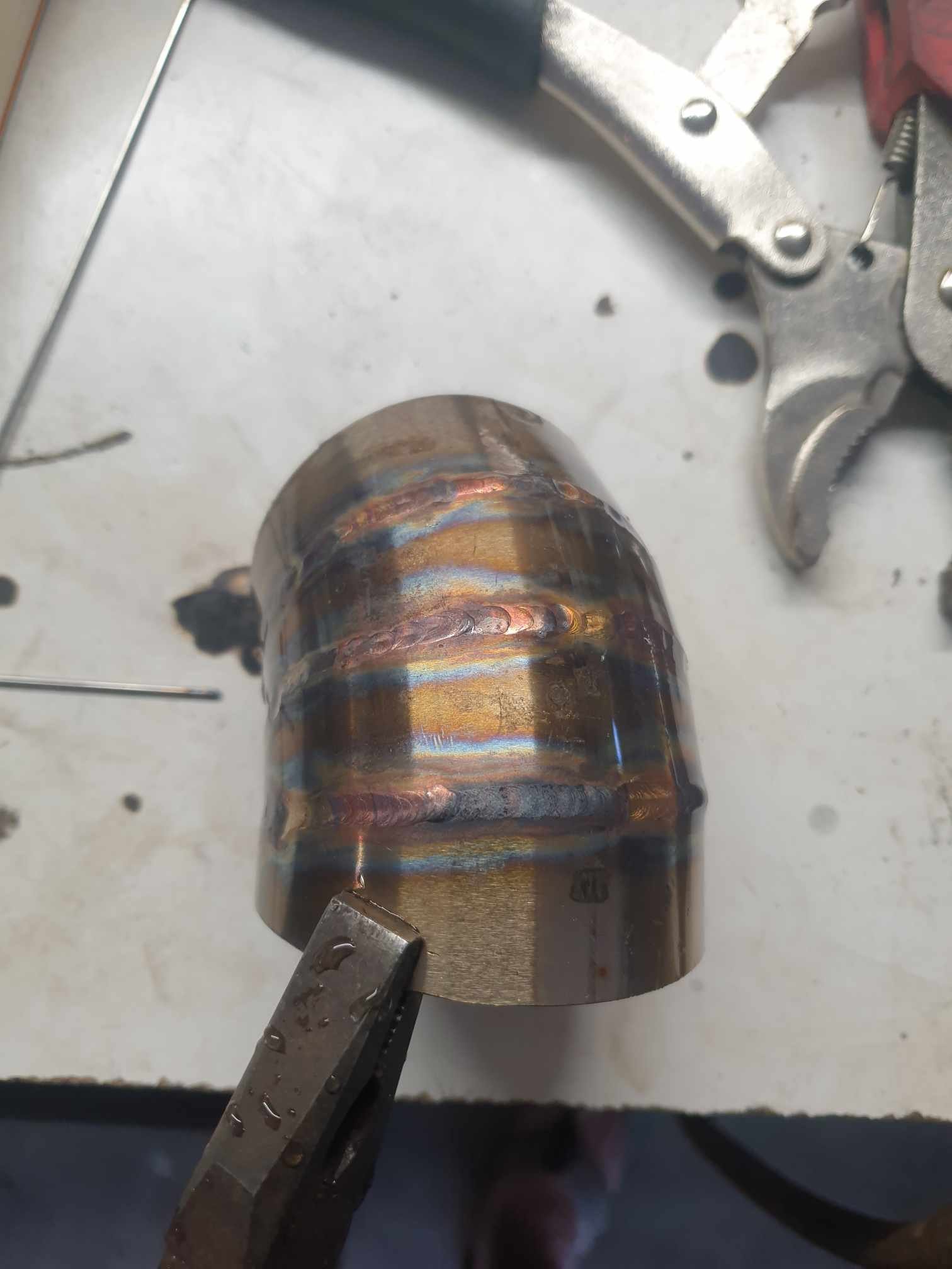
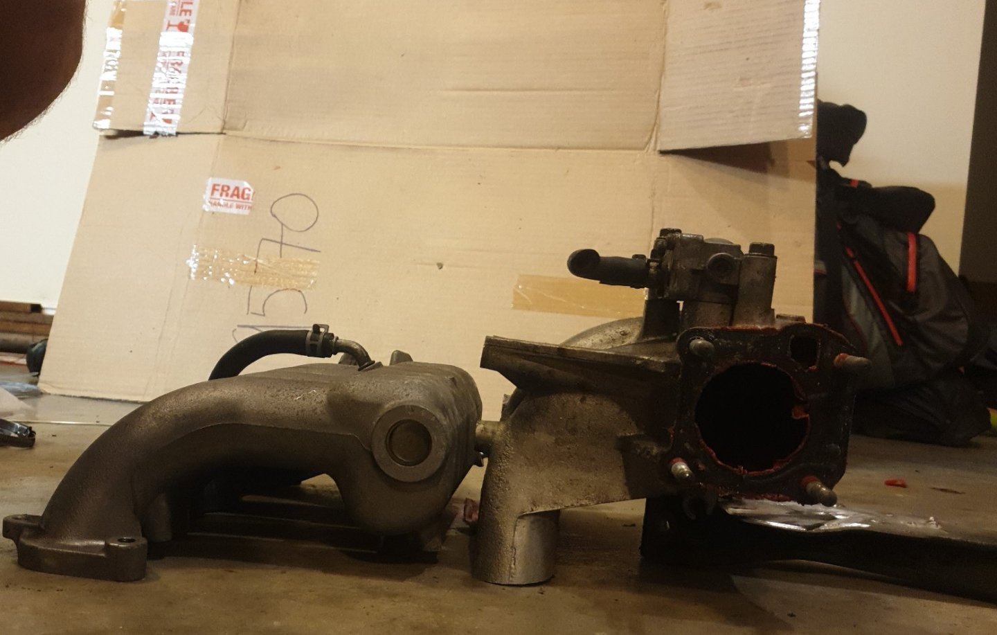
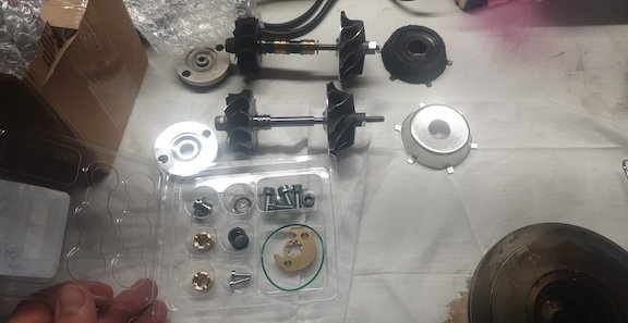
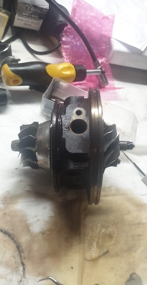
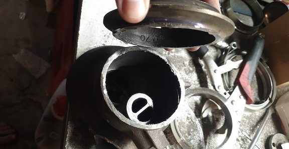
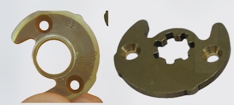
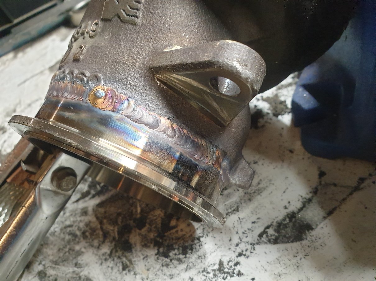
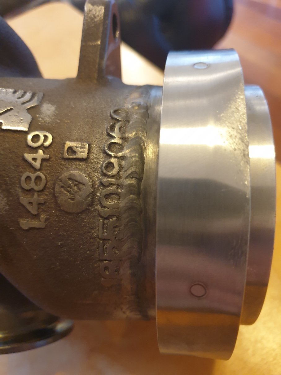
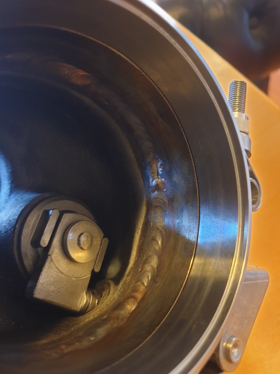
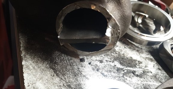
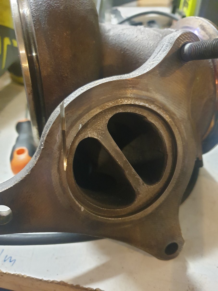
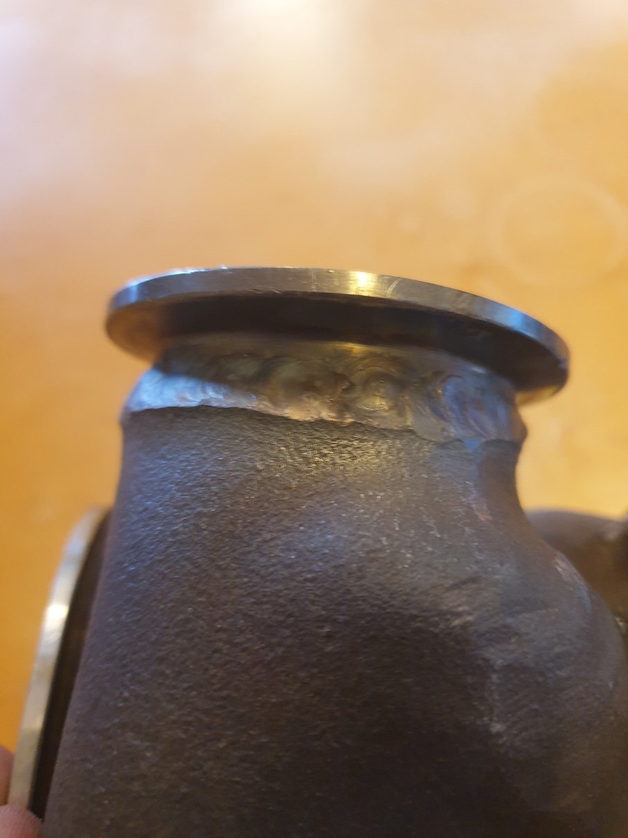
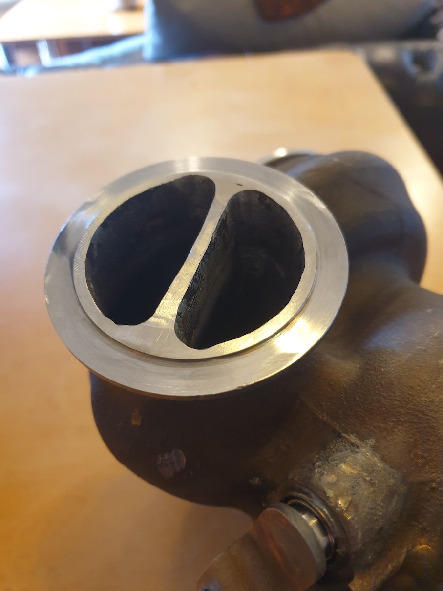
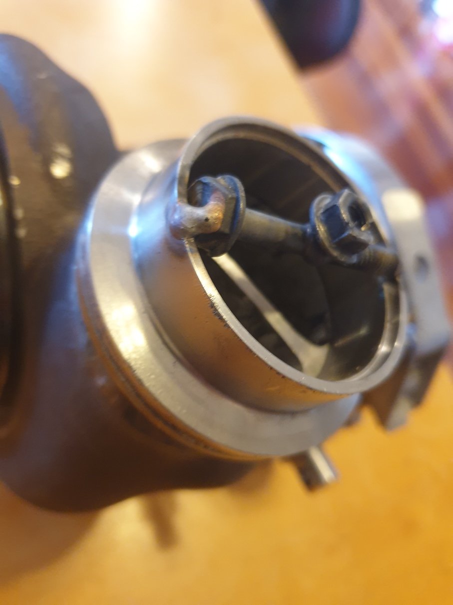
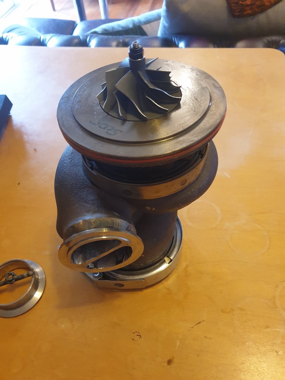
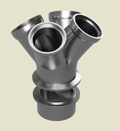
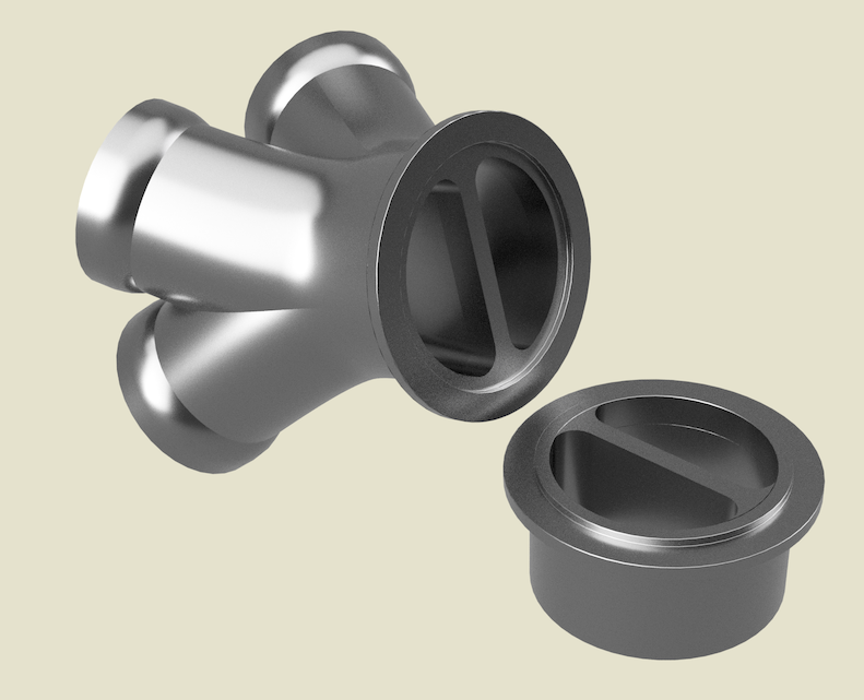
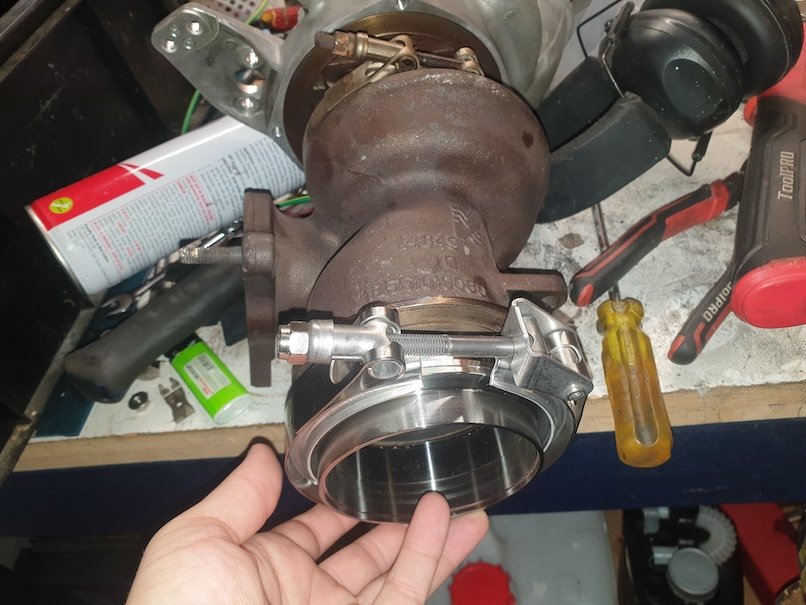
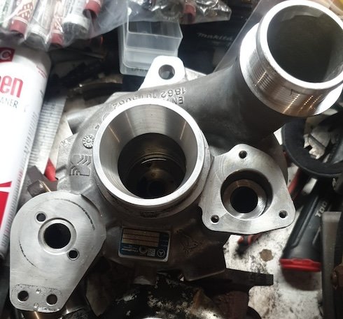
So I did a bit of work to the turbo in preparation of getting it mocked up relative to the cylinder head. Sorry for the photo spam! To recap, the things I needed to do: Rebuild core Weld V-band intake flange, retaining twin-scroll inlet Weld V-band outlet flange Re-install wastegate flapper Figure out twin scroll collector So rebuilding the core was actually fine. I cleaned everything very well, cleaned my workspace (for once lol) and assembled everything very well lubricated. If you pay careful attention in the first picture where everything is laid out, you can see how much of the "extended tip" was damaged on the old compressor wheel. Old turbine wheel was equally flogged. Also comparison of the mangled thrust washer that originally decommissioned the turbo (old on left, the webs are completely gone): Ok so next is cutting off the old flanges and welding the V-bands... The big one wasn't so bad, because the wall thickness wasn't terrible and there was ample room to get the torch inside. The little one was an absolute pain in the ass. The flange was immensely thick so was painful to cut off, welding the inside (including scroll divider) of the flange was near impossible, and then when it was all done the flange was about as flat as a crinkle-cut chip! To resolve the shit welds, I used the die grinder and carved the inside out so it at least will flow semi-well and not get any hot spots (maybe?). To flatten out the flange, I used a combination of the air-file and a jig using the mating side of the V-band which I glued some sandpaper to, and spun around on the drill for about 15 minutes. It came out just fine? Pic of the workhorse of a tool, and how it looks all cleaned up... Removing the old wastegate sleeve was a PAIN. I ground down the flanged face and used a hammer to punch it right through to the inside. To install the new one I basically did the same, except was very careful to not damage it during install. It came out right. Pictures are sort of attached above^. Anyway, heres a pic of it all together (still need to tighten compressor nut and exhaust v-band). Next is to swap the gas bottle over to the AC tig welder and weld the HD clamp to the compressor outlet, then the turbo will be all done. Now for the twin-scroll collector. Reading Roman's Carina posts about his 3d-printed collector really (and him providing very helpful advice) got me thinking "I should just 3d print the matching V-band and collector in stainless". This isn't what it will end up being, but I did a quick model in fusion to see what it would cost. And the answer (for this piece) is about $200USD shipped to NZ! That's practically unreal, as I'm sure if you asked a random fab shop for something similar to this, you would be met with an eye watering quote. So the plan is to mock the turbo relative to the engine, figure out where I want the runners to be, and re-model this collector to have each outlet exactly in the right spot for the manifold. Try to do as little fab work as possible! Then I'll just make the rest of the manifold out of some sch.10 stainless elbows. Thats it for now (hit the 4MB image size limit lol), hopefully I'll make more progress soon!
- 3 replies
-
- 21
-

-

-
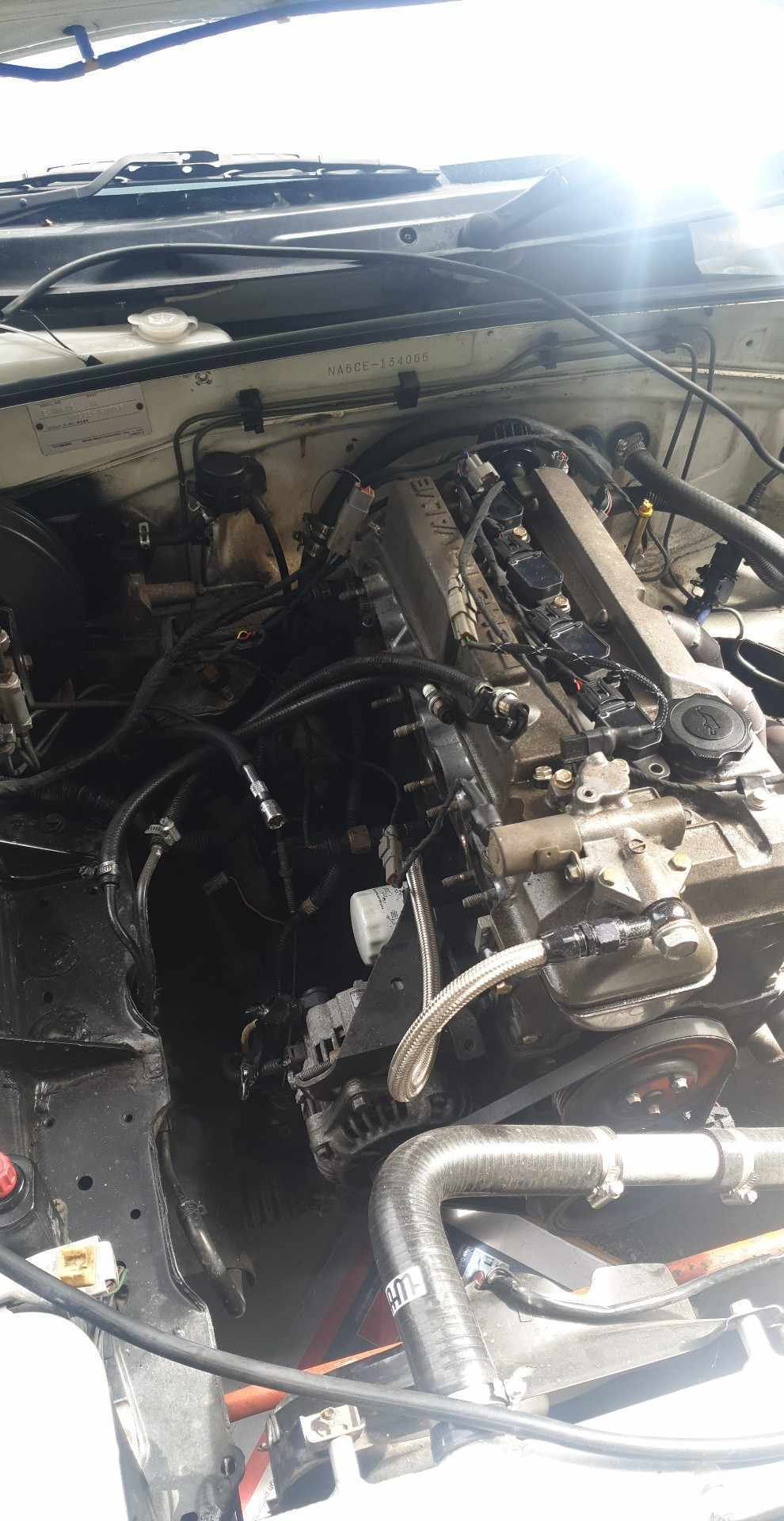
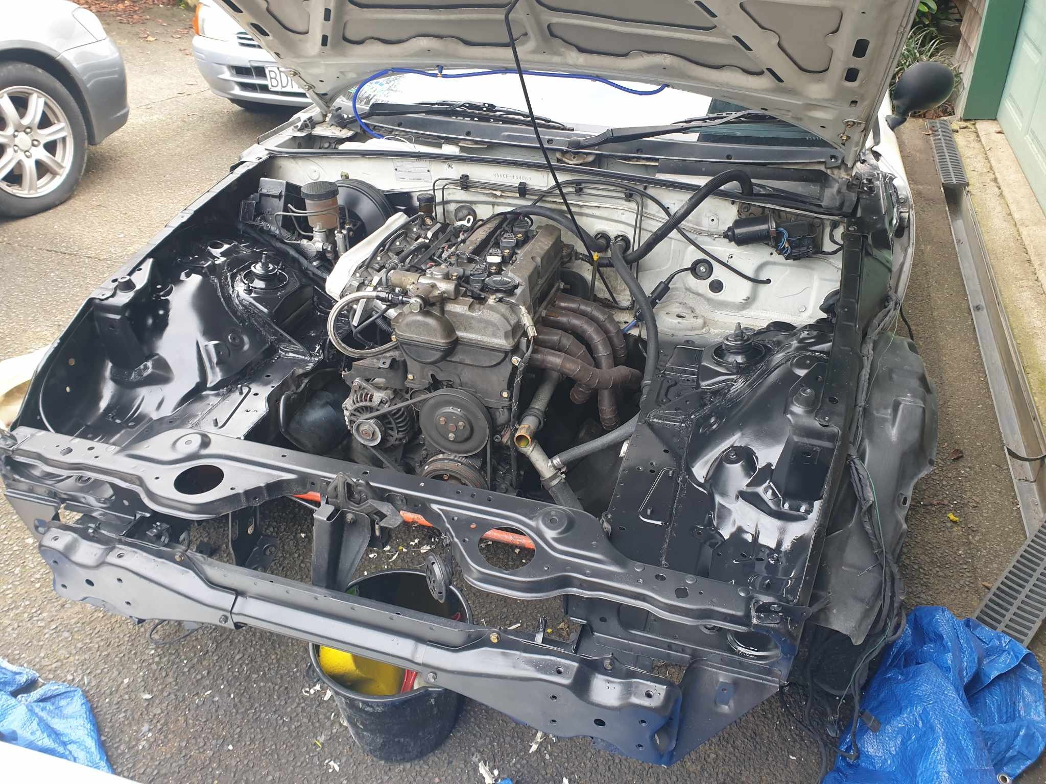
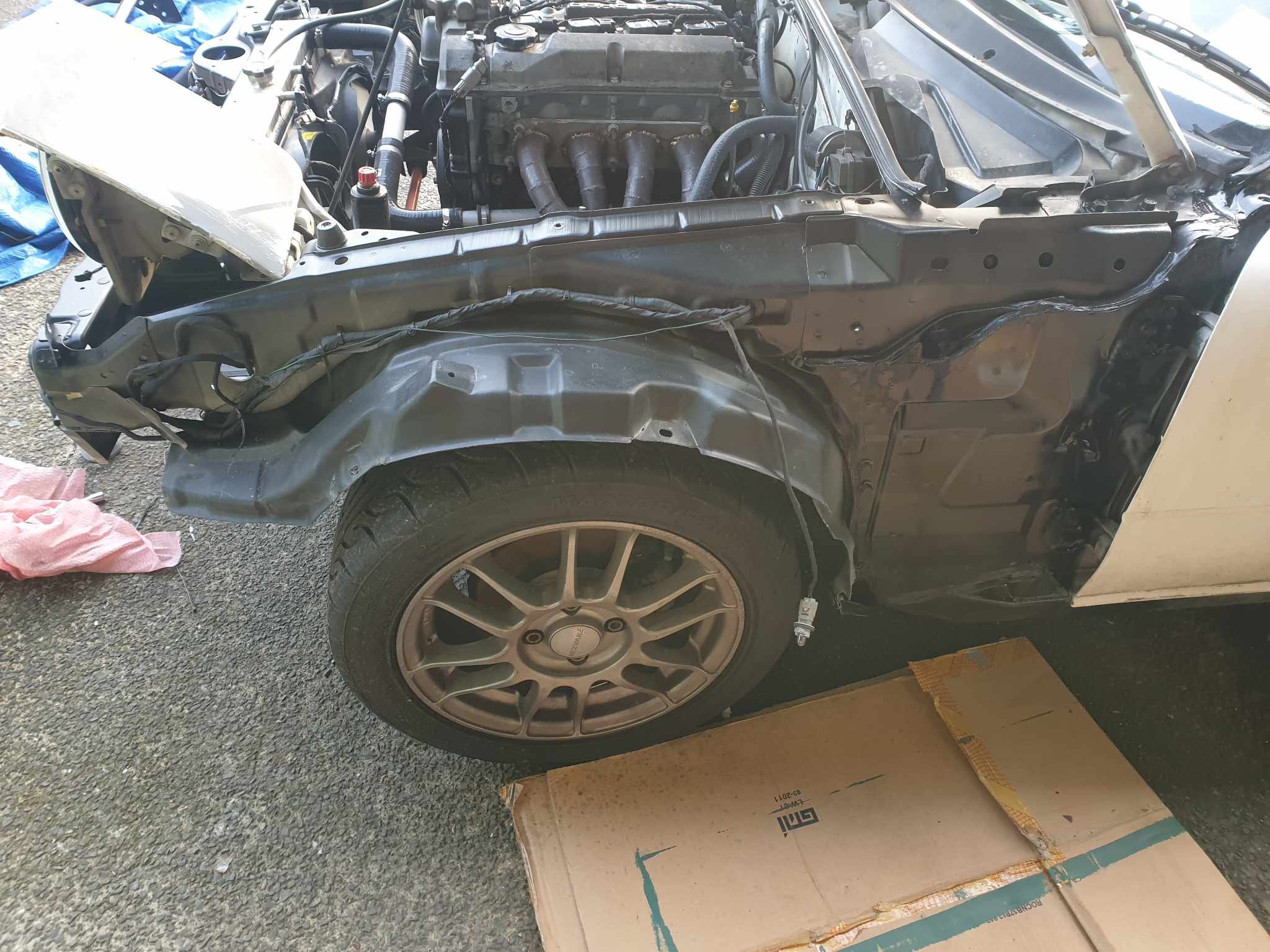
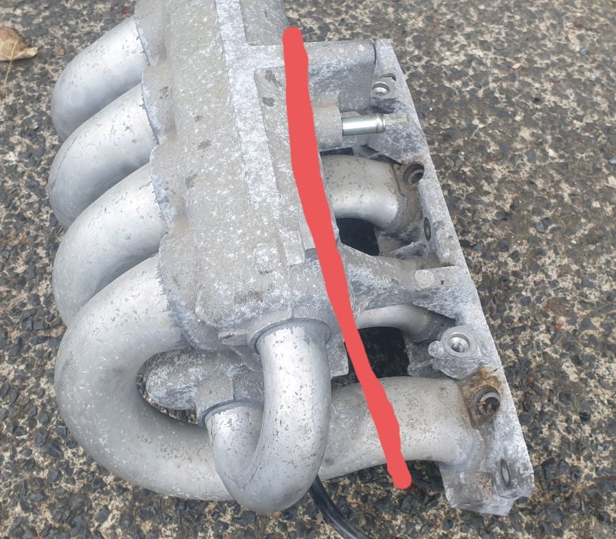
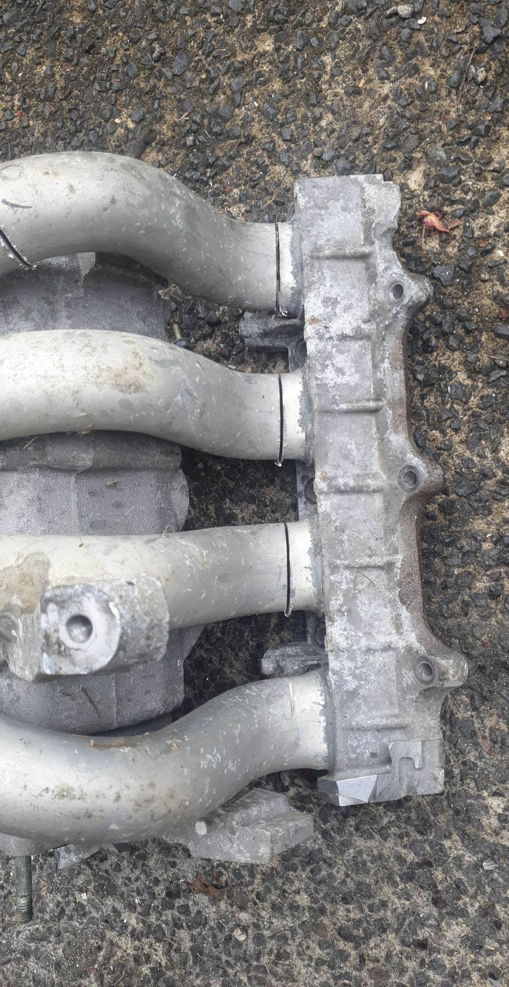
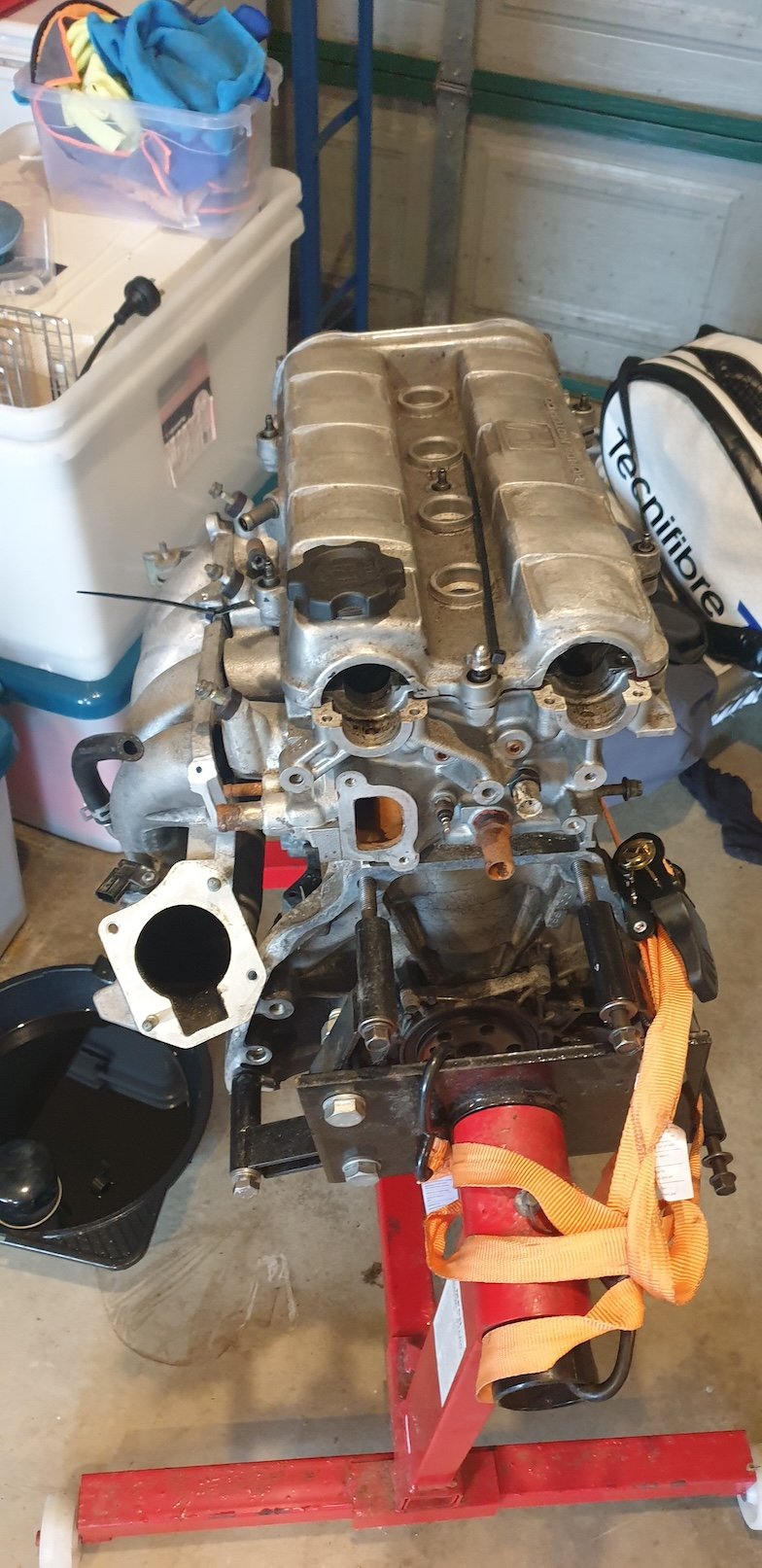
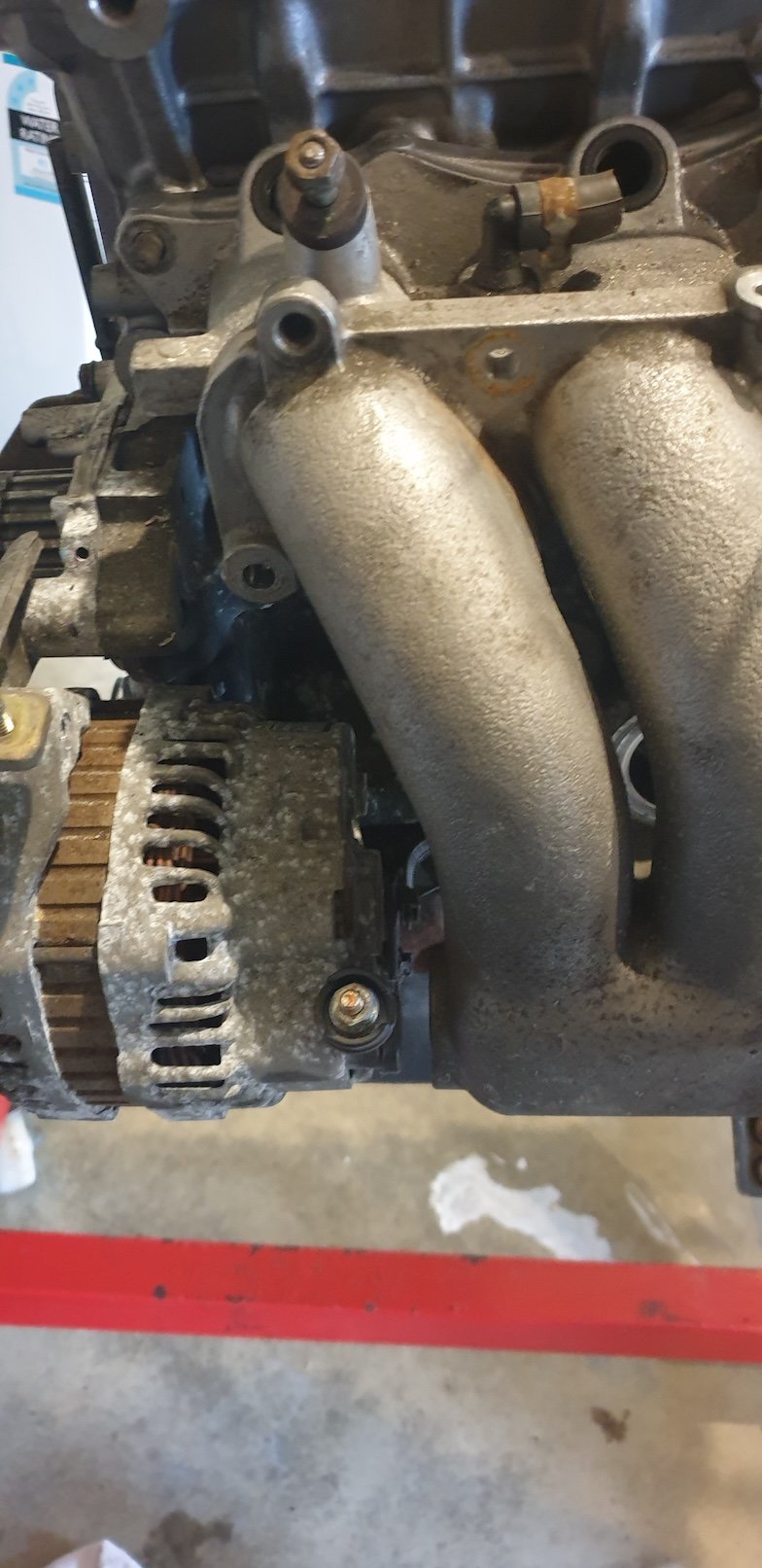
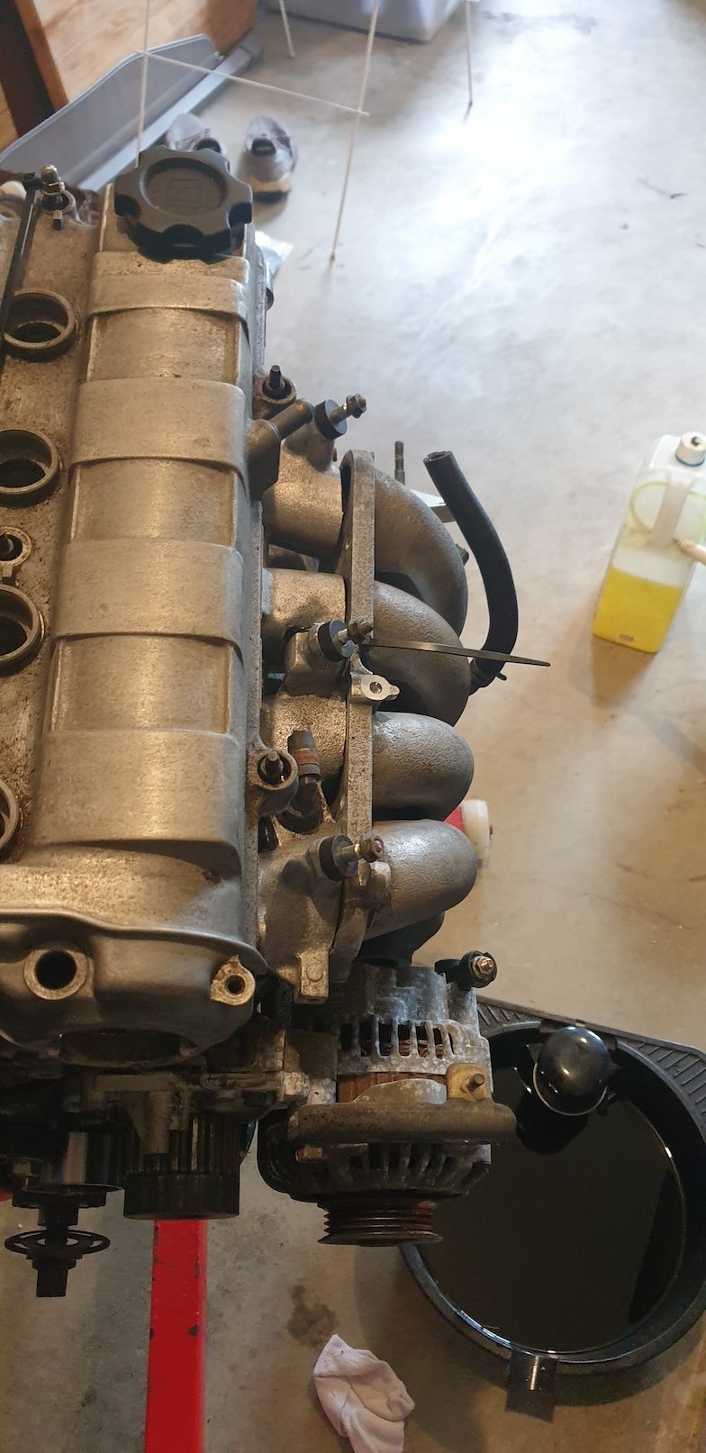
So now that a year has passed I think I can post a broad update here, more a "shopping haul" than anything because I haven't really done anything specific to either the car or engine. I've made the *highlights* bold because this will be a lengthy info-dump. Forced Induction: Borg Warner B03G turbo from a CLA45 AMG (2.0T). It was cheap enough to outweigh the downside of being too large. Not sure if I will stick with it. Part number: 18559700002 Comp wheel: 6+6 blade, 47.6mm inducer, 62mm exducer (extended tip 65.8mm). Turbine wheel: 12 blade, 55.2mm inducer, 49mm exducer. Twin scroll turbine housing, 0.71A/R (I think, it has .71 stamped inside the turbine housing so this is a guess?). The turbo is a bit too big, it specs out somewhere near a BW EFR6258 just with a slightly smaller turbine wheel, and twin scroll. I'm hoping the honda manages fine with this, people run some pretty stupidly big turbos on sohc d-series. If it ends up being too big down the track, I'll happily downsize and use this for a future project. Using the v-band (mentioned below) I should be able to change turbos easily by just welding a flange to the new turbine inlet. Flange for an electronic diverter valve built in, even though the pre-facelift M133 motor didn't have the diverter valve on the compressor housing. I can use the GFB VTA9488 from the facelift m133 which GFB confirmed should bolt right up. Will move to some OEM electronic wastegate actuator, rather than the factory vacuum-closing actuator as it seems painful to work with. Water-cooled core, which is kind of annoying because it means more hoses. Journal bushing not ball bearing, which is fine I guess, saves on cost. Ideally ball bearing would be better, but $$$ for new ones and hard to find used BB turbos for cheap, as OEM's don't really seem to use them? It was pretty trashed The thrust washer was completely worn through, the compressor wheel had been rubbing on the compressor housing. The housing is not very worn, but the compressor wheel itself was destroyed. I've ordered a rebuild kit (incl. backing plate, comp wheel and turbine/shaft) from Turbocentras in lithuania of all places. I'll need to find a way of getting the wheels/shaft balanced as a set. Also ordered a replacement wastegate flapper+bushing. This had the typical euro IWG failure where the bushing completely eats the shaft, resulting in a bad rattle and exhaust leak, plus slow spool due to lack of wastegate seal. The oem flanges are annoying Turbine outlet was some OEM v-band style with an expanded/spun mating surface, which is impossible to find and couldn't be bothered doing myself. I will replace this with a 3.5" stainless v-band. Turbine inlet is some OEM twin scroll 3-bolt flange, which I will have to do a bit of wizardry to replace with a 2" v-band and keep twin scroll, but I think I have the solution in the works. Compressor outlet was a 2" hose barb, which is technically fine but I like the idea of having all o-ringed aluminium couplers, HD clamp style. But i'm forever broke so cheap chinese knockoff HD-clamps will surely work. Compressor Inlet/filter I don't really have to care about it for a long time, as it has to be running to ingest shit. Intercooler I will be using the smallest water-2-air intercooler I can find (or make). One reason is this car doesn't really have a good spot for an a2a intercooler that wouldn't be hanging in front of the front bumper, but also because they seem to be quite efficient (in terms of both cooling and space), especially for low power applications. It will probably add a bit of complexity with having an additional heat exchanger, but the packaging benefits (and easier intercooler routing) make it worthwhile, I think. Smaller intercooler piping should mean less volume to pressurise when coming on to boost, and less volume for the engine to consume when the diverter valve opens. I'm not a turbo guy so I did the research and found that for my target airflow numbers (maybe around 420cfm peak, to be generous), 2" IC piping is plenty to keep air speed below mach 0.3, less than the commonly quoted mach 0.4 where inefficiencies creep up. I'll put the intercooler right above the gearbox, with the IC inlet coming straight from the turbo's compressor outlet, and then feeding directly into the 2.5" DBW throttle (flared from 2-2.5" as close to the throttle body as possible). I'll be designing the intercooler piping and intercooler itself to minimise any hard bends, and try to use gentle radii wherever possible. Reducing hard bends in the system and reducing overall cold-side length should help with overall efficiency. Turbo pictured below after removing the old turbine/compressor wheels, and also with the v-band, just to make the post more fun. I should really tidy up my bench... Intake I was given a K24 RBB (k24 vtec) intake manifold, and had already acquired that RAA (non-vtec) manifold that I had earlier. RBB is larger volume, not sure by how much but its pretty obvious from looking at it that its just larger. RAA smaller volume, could end up being better for responsiveness on the 1.6? This is something I'd need advice on. Also was given an oem K24 DBW throttle body, which I will weld a 2.5" aluminium clamp to for the intercooler piping. I haven't really made more progress getting the intake manifold welded as I was waiting on that throttle body before welding to make sure I left enough room. Pics below what the intake manifold looked like just barely hung on the intake manifold. It just clears the alternator, and is suuper compact against the side of the block. That is the RAA manifold, where RBB is a touch larger but still very small overall. Chassis I haven't taken any more pictures nor moved the car yet, but based on the last time I saw it, the car has a bit more surface rust on the paint than was in the original photos, I will be stripping back whatever I need to, using deoxidine to treat the bare metal and then epotec primer. Will worry about proper paint waaaay down the track, for now thats just to stop the rot from spreading. I've put some thought into what will happen regarding the moving components of the chassis: In the interest of sanity, keeping as much stock as possible would be good. BC Gold coilovers are still made for the 1g civic, so this will probably be a go. Although that will be after the car is at least running. I'll need to replace all of the brakes, to match the power, but using oem stuff is a no-go. The civic is 4x120 from factory, with discs up front and drums at the rear. This is annoying for wheel size and replacement brake parts. I've found that based on the bearing sizes, I can probably get oem driveshafts that work with my gearbox and pick up matching hub centers for those axles, as long as they are 38mm pilot size. I can then use a 38mm ID, 72mm OD, 40mm deep wheel bearing (reasonably common) to replace the factory bearing, which had a slightly smaller ID and less depth. This way I'll be running 4x100 disc fronts, and make up some caliper adapters to run more modern front calipers. Driveshaft length will be interesting, I haven't really looked too far into what driveshafts I will need but there is a small chance I'll need to have some made with a shorter shaft to match the narrow track width, and engine being slightly shifted back compared to most D-series swaps. Rear brakes are undecided. I was looking at finding a rear subframe and just swapping the entirety of the rear suspension/brakes, but this seems not worth doing. The older guides use wagon knuckles to do disc brake conversion. I found someone saying you can use '88-91 EF civic hubs bored out for the 1st gen rear bearing, and use 92-95 EG rotors, calipers, handbrake cables. The engine bay will need some modification to fit the engine still, mostly around the snout of the gearbox. Everyone who does a D-swap in these chassis modifies three main areas: firewall, drivers side chassis rail and passenger side chassis rail. Firewall I've resolved by changing the intake manifold as mentioned previously. Drivers side (gearbox side) chassis rail is a huge modification to clear the snout at the end of the gearbox. I'm not sure it needs to be quite as big as some people make it, but it definitely needs a good cut taken out of it. Overall, I'm hoping to lower the engine a small amount also by modifying the sump to be shorter, with wings and baffles. This should still let me keep enough oil volume but have the engine low enough to reduce the amount of modifying of the driver side chassis rail. Passenger side (timing belt side) chassis rail is often trimmed to fit all of the accessories. I'm only running an alternator so I'm planning on either facing down or buying an aftermarket single-belt crank pulley to reduce the cut required on this side. Ideally I'd make no chassis modifications, but I won't know how bad the interference is until I actually get the engine in the car. Pictured below is someone else's chassis modifications to show what I mean about notching each side, all credit to their post on honda-tech.com. ECU uaEFI ecu, with an adapter board made to run a better automotive connector. I'm still cheap, but this time speeduino doesn't have the features I want. Ideally I want to order three, one for the mazda, one for a future project and one for this, but I might get 5x made by JLCPCB as the price really decreases with quantity. The ecu has the hardware to support 2x DBW controllers, one will be used for the throttle and other will be used for electronic wastegate. It has enough other I/O for pretty much everything else I want to do. rusEFI firmware has quite a bit more complexity and features than speeduino so there will be a learning curve, but that's where the fun is right? Engine Literally haven't touched the ZC bottom end besides spraying it with a waxy water displacement coating a few times to prevent rust on bores/bottom end parts. Still need to notch the bottom of the cylinders and girdle for the rods, then assemble with new gaskets. I did get given a d13 block, which is almost identical to the ZC block except (from what I can tell) 7mm less deck height. So with a 7mm spacer I can use this block for mockup purposes in the chassis with the ZC head, while I wait on money to continue with the engine itself. I plan on not really doing much to the head except source cheap-ish HD valve springs and get the cams reground for a bit more lift/duration. The head is otherwise in very good condition and has brand new valves/guides so it will stay as-is. Anyway, back to another year of doing mostly mazda stuff before posting some inconsequential update!
- 3 replies
-
- 12
-
-
-
I think my friend had similar if not identical issues to what you're facing re the TPS and fuel pump. If you want to PM me about it I can put you two in touch. The adapter boards went through a few revisions and did need some work to get every feature going as expected. While you're in there you should do the ULN proto board stuff for the tacho, saves from having to "do it tomorrow" for years... Not that I'd know about that? https://speedyefi.com/ulns-and-pullups-and-launch-oh-my/
-
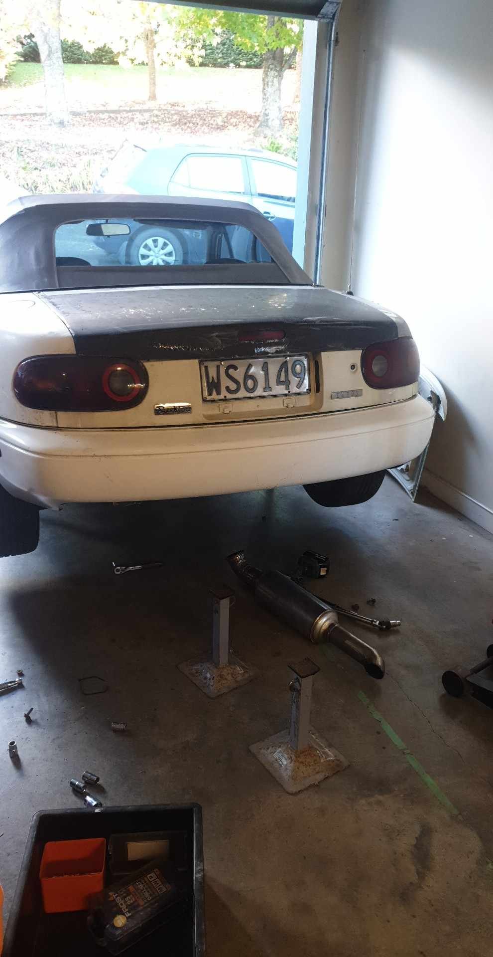
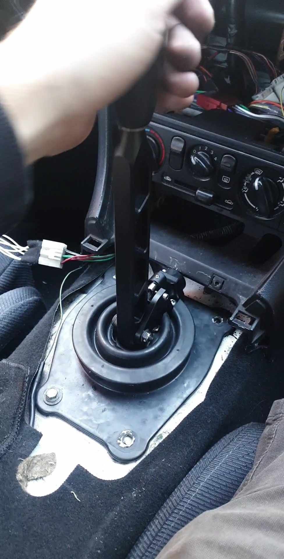
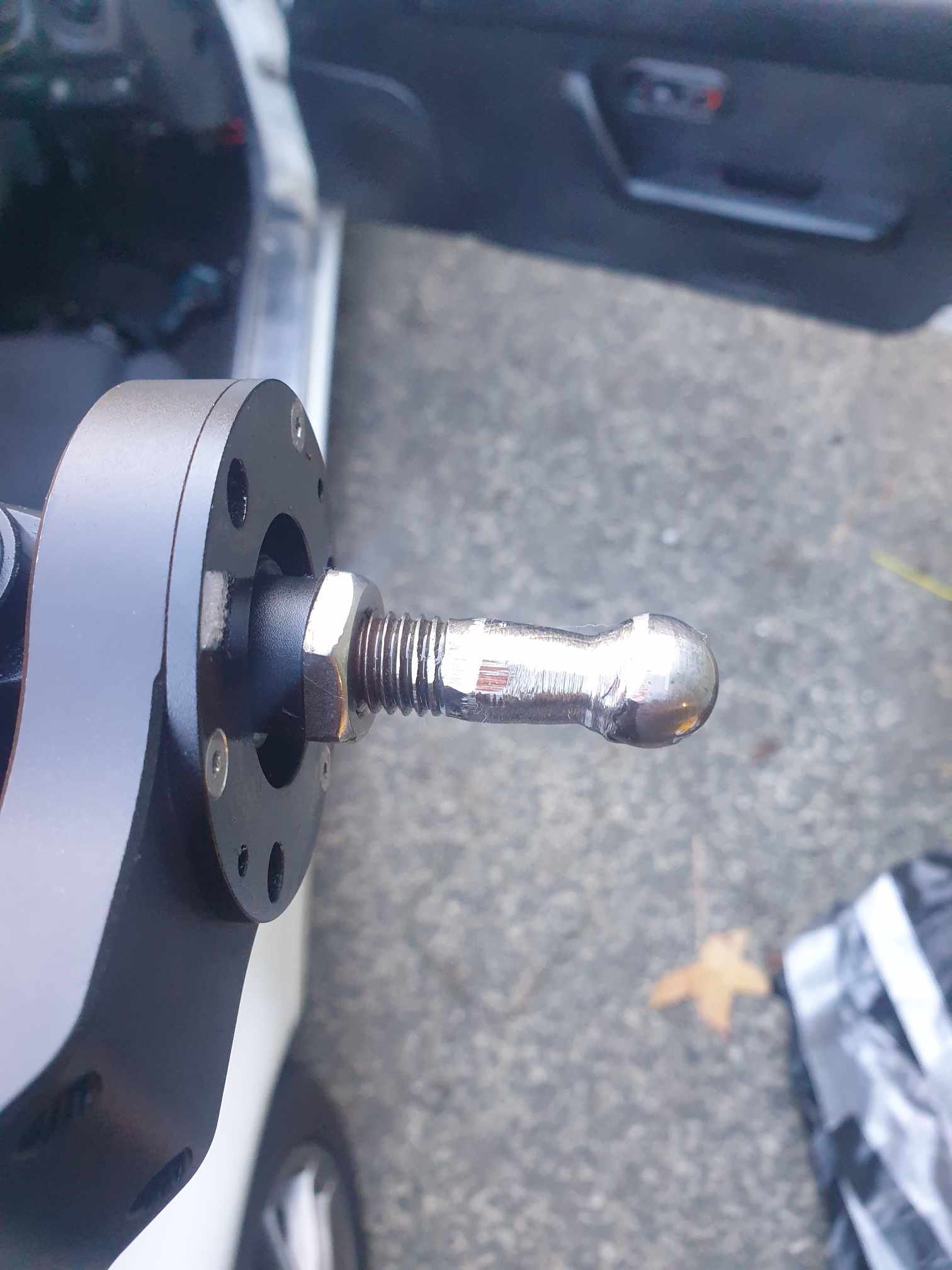
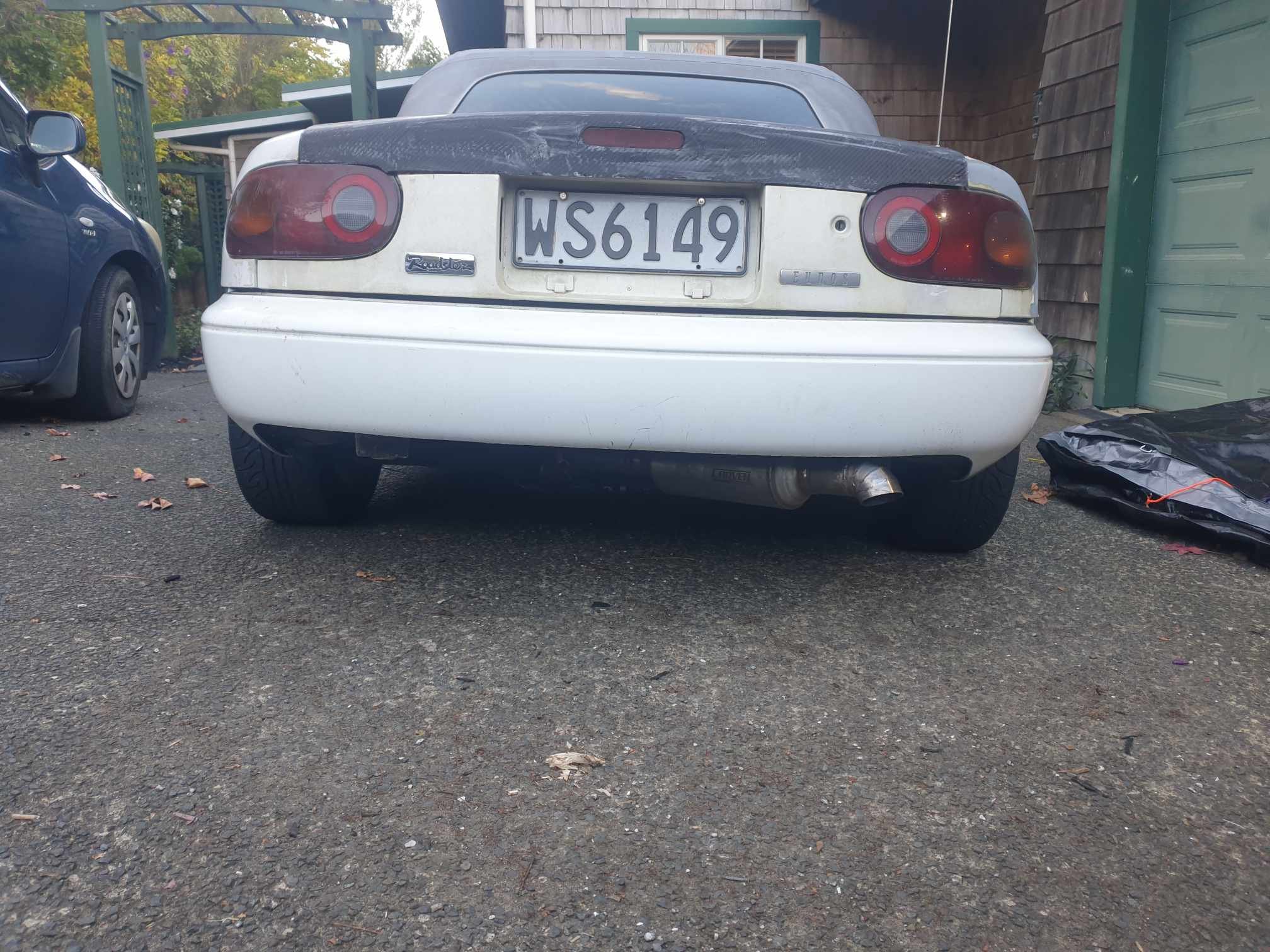
Free, inconsequential update time. I "acquired" a clone of the irp-style short shifters a while ago, one of a batch that had some issues and was essentially worthless. The issue is it didn't come with the lower ball, so I had to make one. 304SS 15mm ball bearing welded to a cut down M12 bolt, and this problem is solved. The shifter is really nice, its super notchy with the brass bushing (unsure how long it will last) but I do plan on cutting the shifter and welding it in a "Z" shape to bring the shift knob closer to the steering wheel a little bit. Something like the offset shifters you see as an option on quaife(?) gearboxes. Next free thing was yet another exhaust change. I'm about to move from those trade'n'go argon bottles at bunnings to one of those fancy F3VIPR bottles, so I need to refill gas less, and it costs me significantly less in the long run too. I need to use up the last of the argon so I decided to move my exhaust tip to the other side, mainly as tig practice but also to provide one more bend for the exhaust gasses to travel around. This also let me use more exhaust hangers (not pictured). Also the towbar is gone I decided it was time to say goodbye to my dream of towing boats, car trailers and campervans with the mx5 and decided the 20kg or so was not worth it (lol). Also pictured is the CF bootlid my friend made before selling his car. It still needs a final trim, sand and 2k clear but it looks kind of neat. Not sure if I'll end up sticking with it or going back to the white painted boot but for now it's on there
-
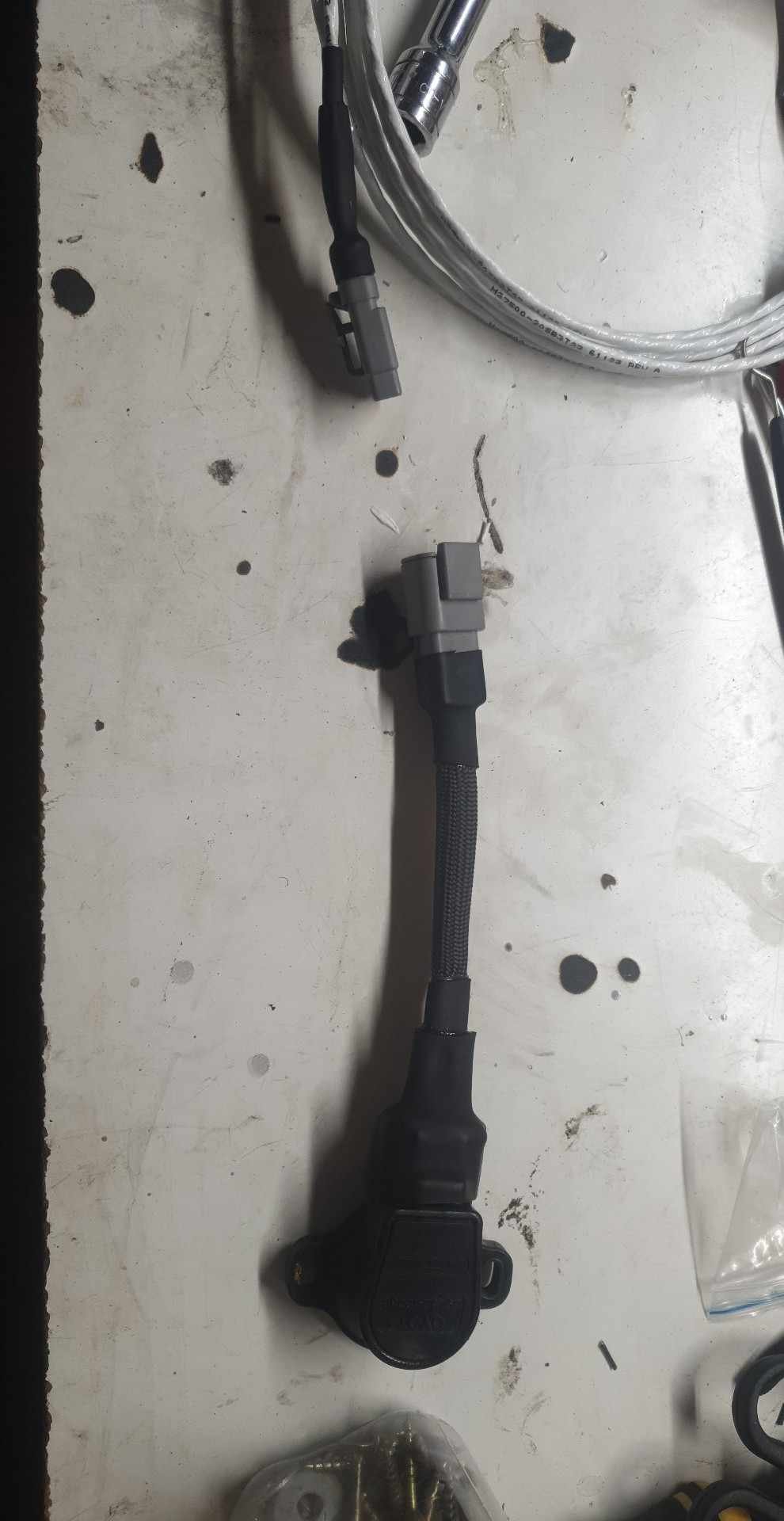
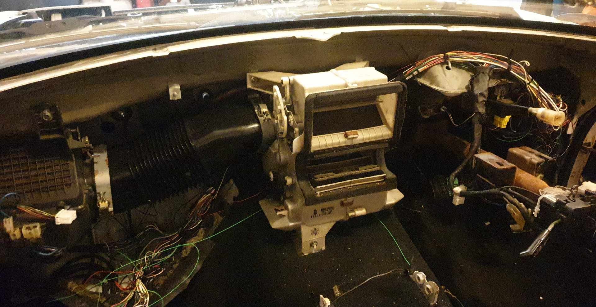
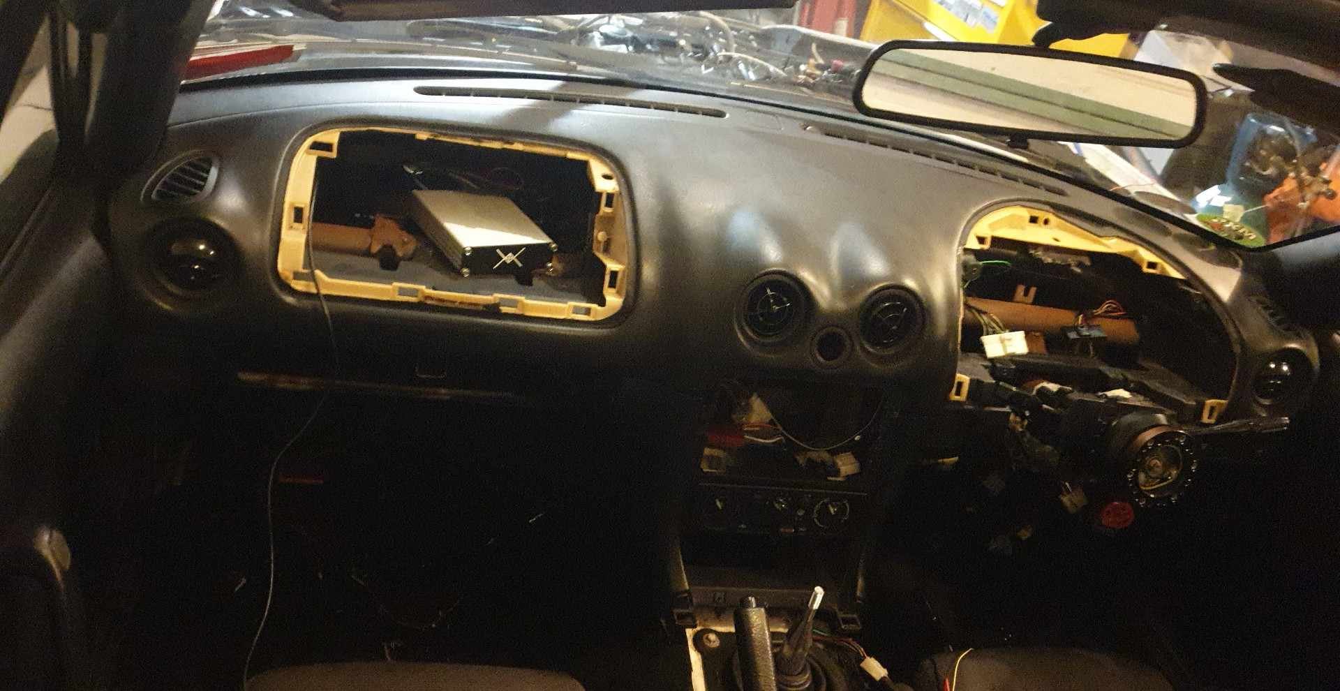
Another SCCNZ motorkhana on Sunday 5th, so of course I decided to do a full re-wire on saturday. Okay not a full re-wire, but I re-pinned everything on the ECU side, replaced the TPS wire and connector with 3 core+shield, and ran new wires for IAT and CLT. This photo was at about midnight on Saturday night, pulling the dash is a REAL pain but boy I'm glad I have a convertible. You can see the old bodged birds nest of wires in the passenger footwell. The motivation for these changes was that every analog sensor seemed to change a few percent based on RPM. So at 0RPM the sensor read "normal", but for example CLT increased 10* linearly with RPM, which is not how engines should behave so is not what we want. The other oddity was that my TPS signal had about 1-2* of noise, and that noise was hitting acceleration enrichment at cruise, resulting in weird rich conditions. Additionally I moved every single splice on a 5v or sensor ground out of the engine bay/loom and put them all into "bussed" connectors right at the ecu. Basically some cheap fake deutsch 4 or 8 way connectors with one side all bussed together. That way I can add or remove or replace ground or 5v wires if necessary without having to replace open barrel crimps in some awkward position under the dash or in the loom. The twin 4-ways are 5v, and the 8-way is GND. I did this so I could never accidentally plug them in to the wrong one. Also to solve some space requirements I potted the TPS connector and ran it to a 3-way deutsch connector in the engine bay. At about 2.30am I got the dash back in, and test fired it. You can see the ECU's new home in the dash, preventing passengers feet from strain testing my crimps. I was fully expecting nothing to work, but weirdly enough the car actually started up fine and ran. Unfortunately I made a mistake somewhere (?) and both CLT and IAT read strange, but they have 5v so I suspect I just swapped which ecu pin I put each to. I went to bed. The next morning I got the car "properly" running, assembled the rest of the dash and headed off to the motorkhana. I also changed the tune from hybrid SD/alpha-N to pure alpha-N and turned down the acceleration enrichment. It helped a lot. One of the issues I had with the blended system was that my acceleration enrichment curve meant I needed heaps of fuel for large ΔTPS at low load (SD, map-based load), but as load increased and it swapped to alpha-N, the amount of required fuel was less. My understanding is that this is because TPS updates almost instantaneously, but MAP can delay a small amount (in the hundreds of ms) so you use ΔTPS as a stopgap to throw in a bit of extra fuel until the map sensor catches up. Unfortunately if the ΔTPS means you are now using TPS based load, then the required fuel causes a rich condition. More tuning is required, but mostly I do acceleration enrichment by "feel" not what the AFR says. If it feels peppy, it's probably good. I'll post another update soon if I can eventually find any photos of my car from Sunday's motorkhana.
-
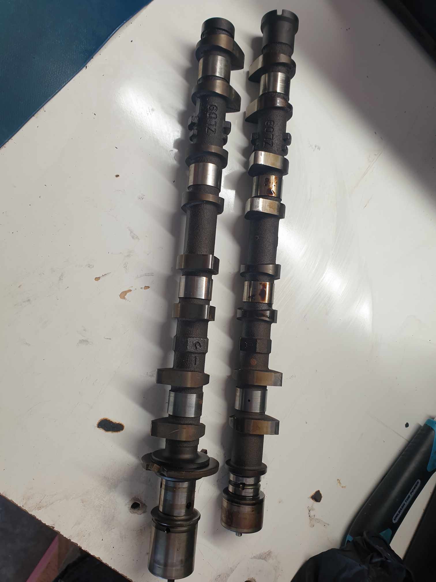
Yep! 226/233, less lift. Same with the ZM-DE (I've had a friend measure the ZM-DE cams and theyre actual trash). Also yes, unfortunately. Its the only VVT motor Mazda made with this cylinder spacing so I'm almost certain its the only cam thatll fit. Thanks for the suggestions though, I wish I could grab some off-the-zebra (RIP you will be missed) cams for this but I think getting regrinds is the only way, given the fancy oiling they had I don't even think brand new cams from a billet would be cost effective. On these cams, the intake cam has all of the oiling setup for the VVT system so I'm not so certain anything will drop in. The cam journals are all oil fed from the head. On the exhaust cam, the cams self-lubricate from a single feed on the frontmost cam journal, which is distributed throughout the cam through tiny wee oiling holes on the rest of the journals. The exhaust cam has more lift and duration than a B6 intake cam I think, so it could maybe end up being a cheap drop-in exhintake cam for NA 1.6 mx5s? To be looked at further, by someone other than myself. Another point of interest is that the backs of the lobes (in the base circle) taper really narrow, does anyone know if this is an issue with re-profiling cams?
-
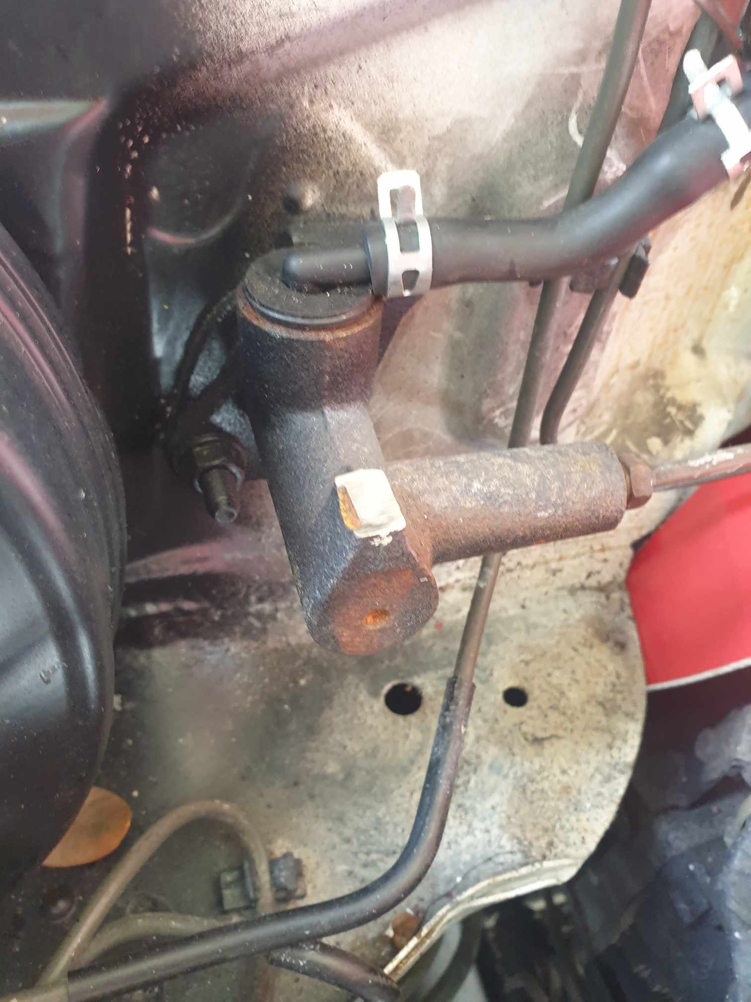
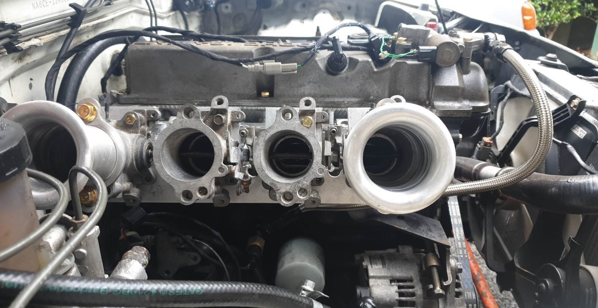
Woah 2 updates in less than a year? I must've had too much caffeine. The plan is: Remove the intake manifold. Grind down the clutch master where it touches the TPS. Less sketchy than it sounds, its just a mounting tab for the old reservoir. I kept the master wet to cool it while cutting. Remove the throttles. Tidy up the mating surface between the intake and throttles. Drill out the threaded mounting holes for the throttles. The tapped aluminium was always a bit sketch, I never had the confidence to really tighten down the mounting bolts for the throttles. Grey RTV the mating surface, longer bolts with nylon locknuts on the back. Re-install the things. Hoon. So, intake off: Clutch master cut down: I did the things I needed to on the manifold, I also trimmed down the flange a bit to be less intrusive (compare with older photos): Back together: Aaand in the car: Results: Started first pop, was running like shit and my exhaust spat out more fuel than the last 15 seconds of a prepaid BP pump (not hard). Turns out you need your MAP hose connected (seen by my washer bottle/chassis tag in the previous photo... lol). I guess the vacuum gave enough fuel for it to run super rich, basically WOT fueling. On the first drive the car was fine. The cyl4 vac leak was gone as expected and I'd spent more time grinding out the inside of the intake manifold, so some of the weird whistles I used to get seem to have gone. Datalogs looked expectedly poor. I had some help from a very knowledgeable friend about some oddities in some analog sensor readings and we have determined I should probably both chase my grounds and make sure everything looks fine, and also change back from a hybrid SD/alpha-N tune to pure alpha-N, with a bit of analog smoothing on the TPS signal. This will help resolve the very difficult to tune accel-enrichment values and hopefully result in a better driving experience. Future: I think besides all of the constant fixing of past-me's neglectful corner-cutting, I need to really look into longer duration cams. I believe the 230/240 8.5/8.9mm values really aren't enough for the kinda tomfoolery I would like. As the ZL-VE cylinder head has really never done much more than haul groceries, nobody makes cams for it. Regrinds are in order and I will try to take as much inspiration from the NB VVT engines as I can. Maybe 270/270 9.5/9.5mm which purport to be fine for shim-over-bucket lifters. Realistically, moving to shim-under-bucket will cost more than the cams. I think my engine will become interference with the cams I'm wanting, mostly because the stock b6 pistons have the valve notches for the wider cam spacing (obtuse valve angle) and the valves being closer to the piston when at rest in the ZL head. Oh well, it'll be fun while it lasts!
-
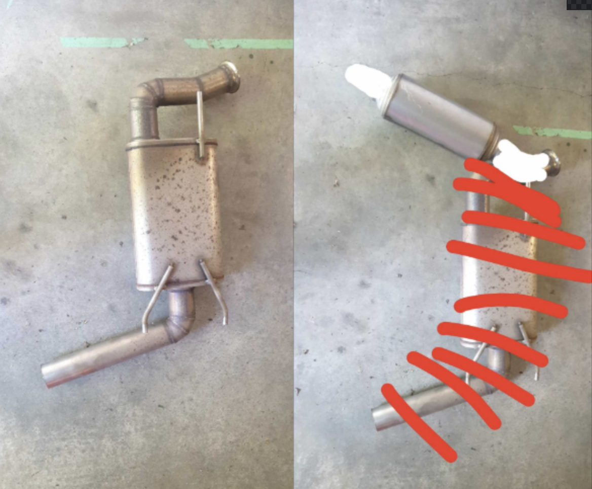
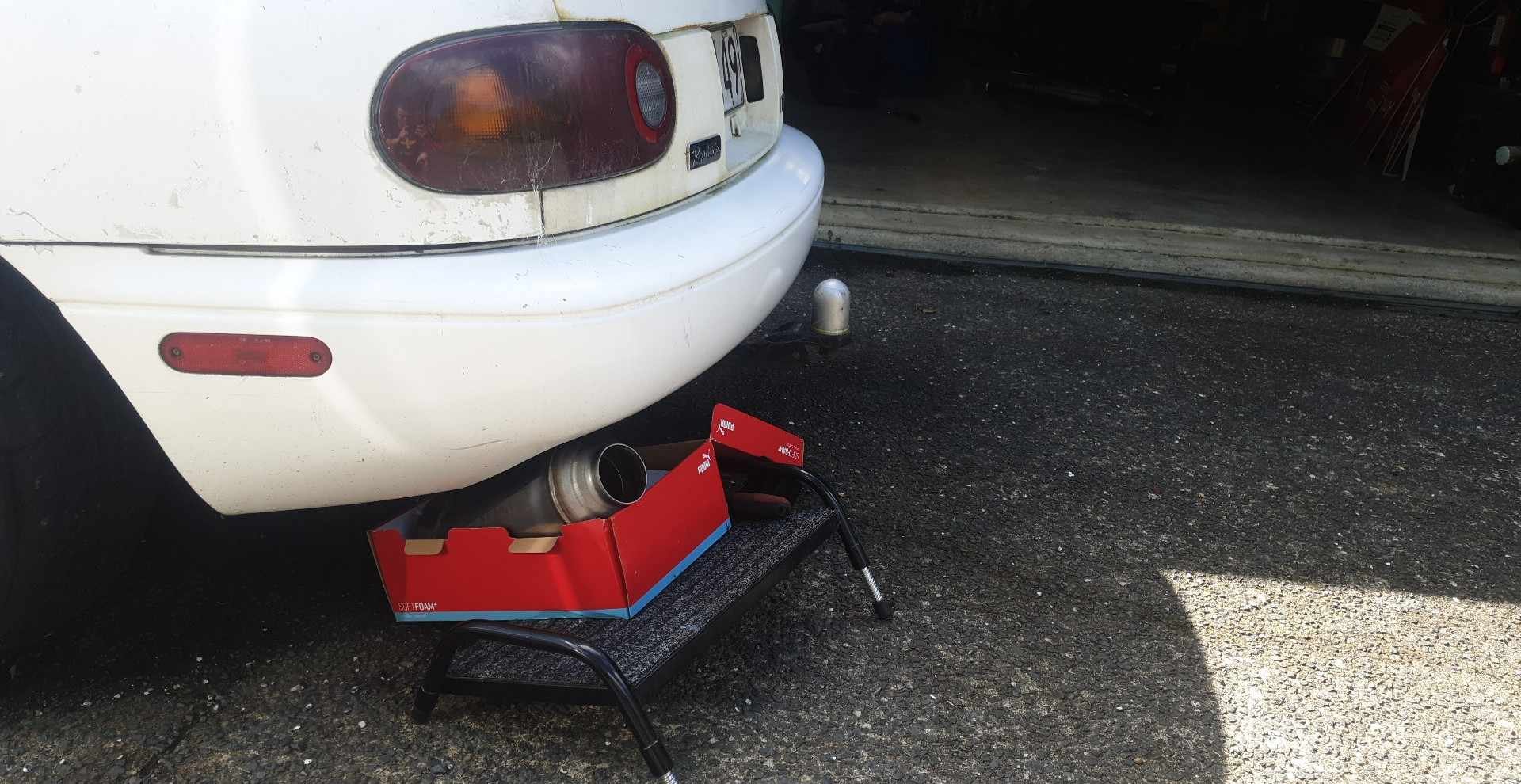
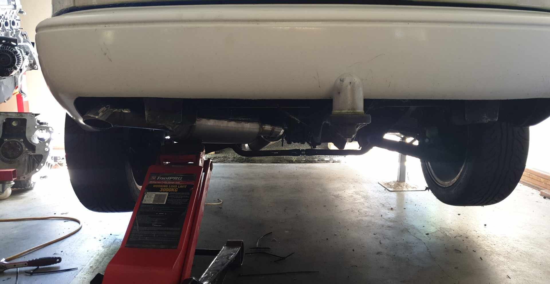
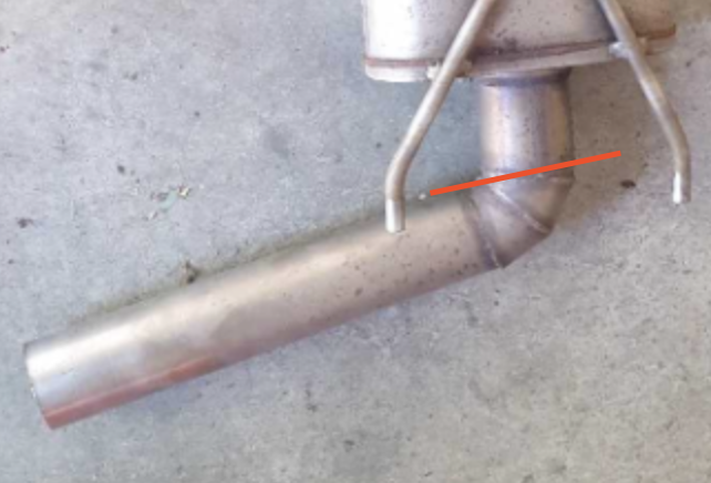
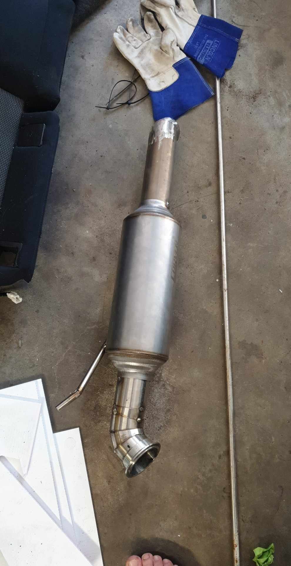
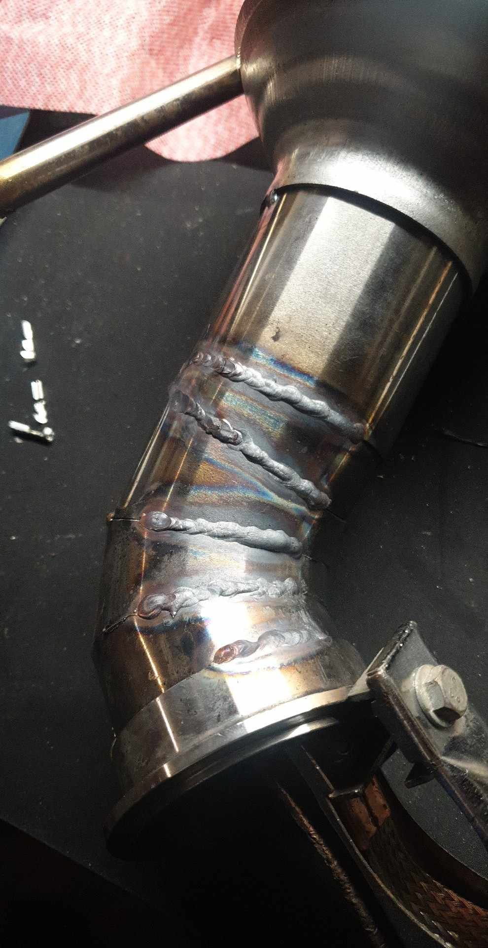
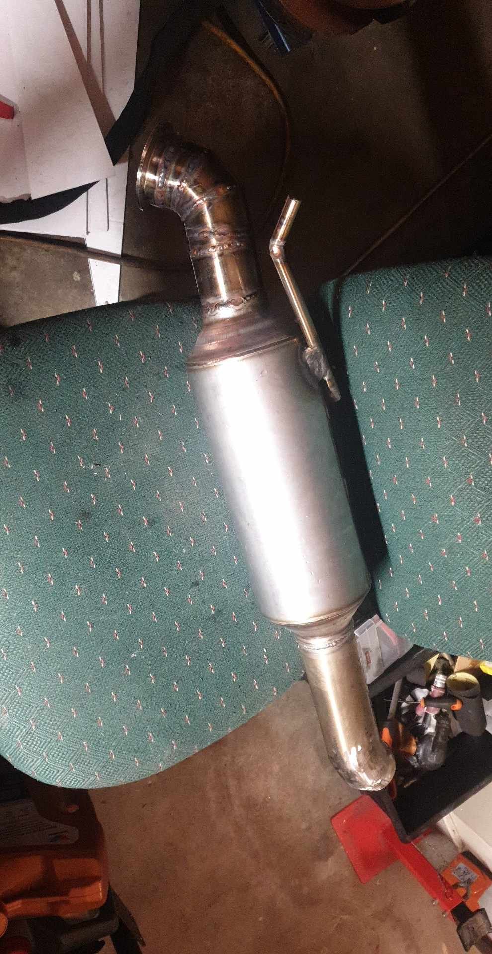
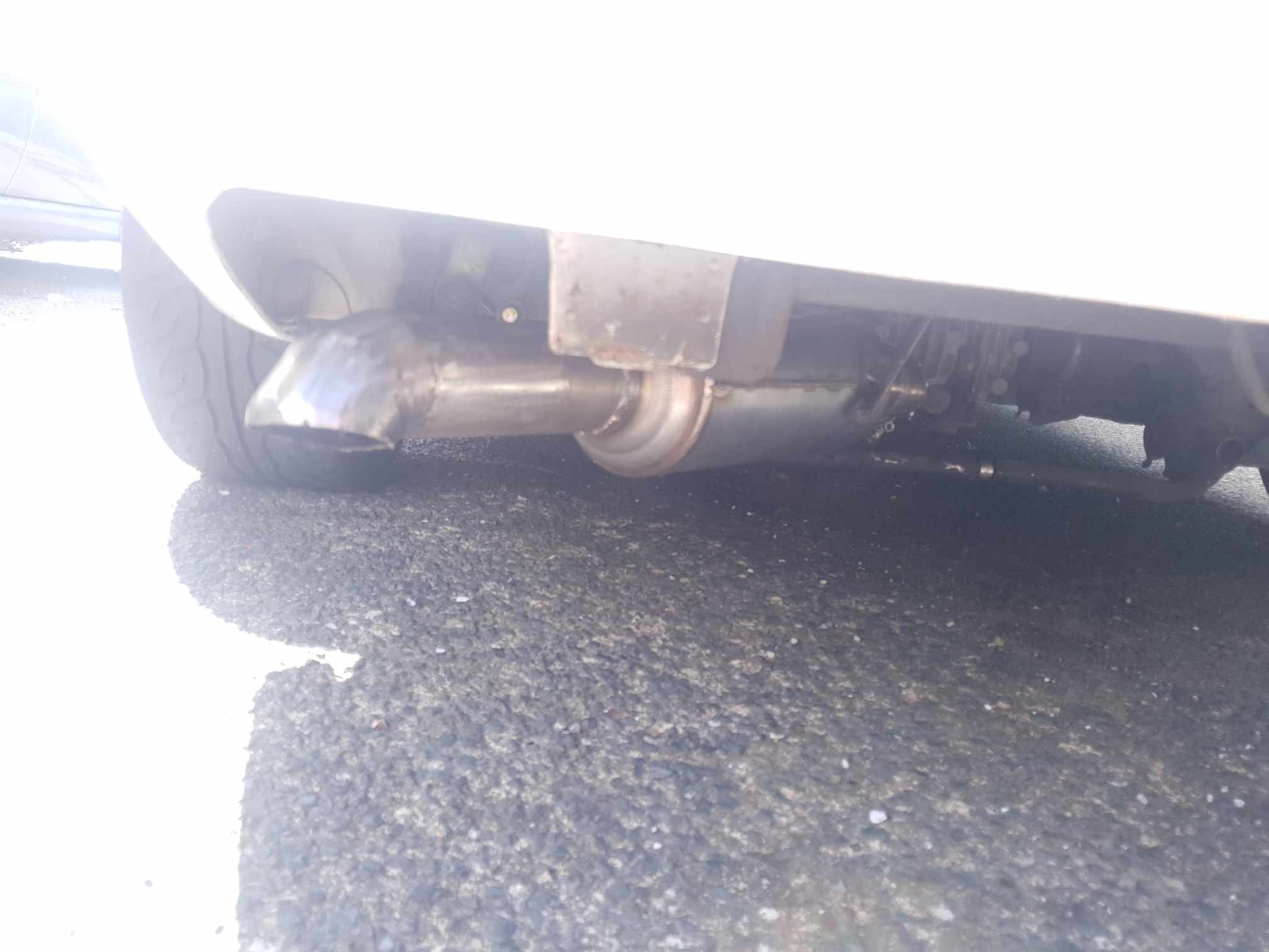
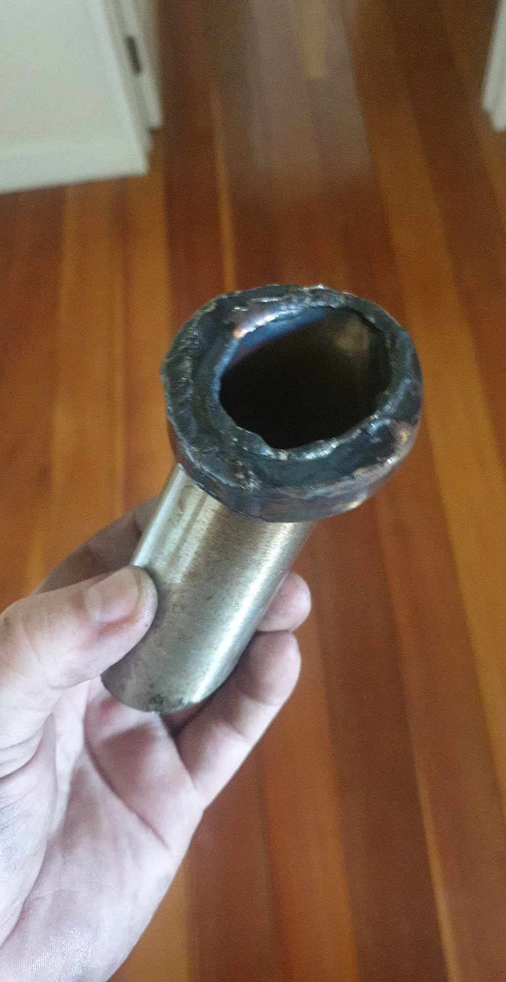
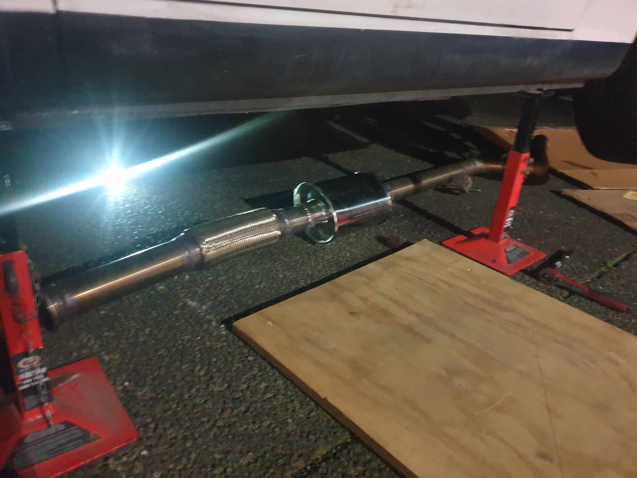
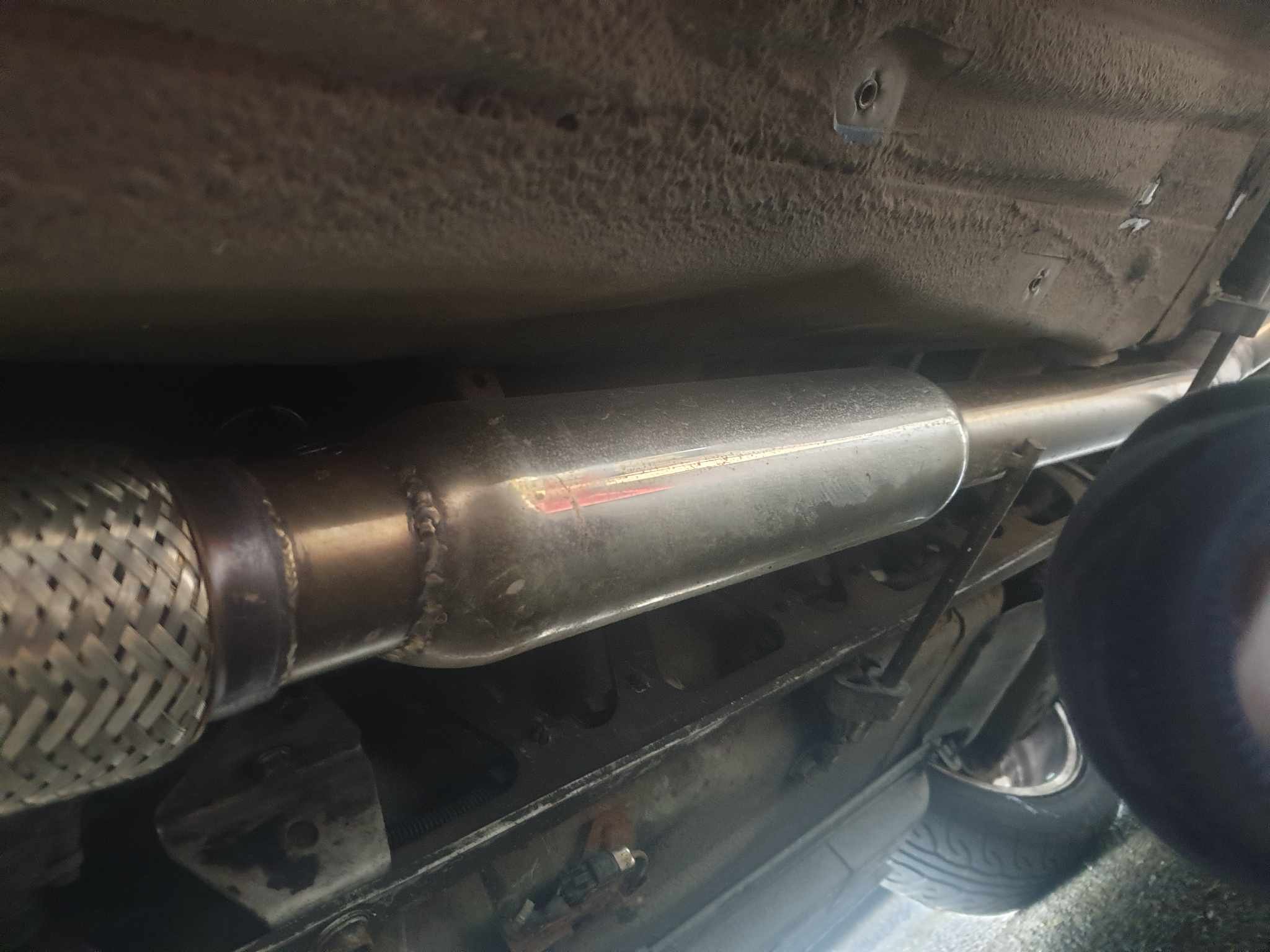
Another few months of nothing and then I decide to sign up for another sccnz motorkhana. At this point it is 10am saturday, and the motorkhana is 10am sunday. Last time I checked, my TPS is falling off, throttle #4 has a vacuum leak from being yanked about when the tps was knocked, and there is maybe a slight misfire. Instead of even opening the engine bay, I decide the exhaust needs more work and I have a muffler just lying about SOOO a plan is formulated... I'm also critically out of stainless filler and argon, but that won't stop me Contemplating new muffler position, was tempted to have it riight out the bumper but I don't hate myself that much. Instead, we tuck the muffler right up underneath the car and do a downturned exhaust tip. At this point I was chopping up the old muffler to save argon. Here is where the downturn tip came from: After procrastinating a fair amount, I get the muffler all tacked and have completely exhausted my argon bottle. Nice, its about 3pm and I'm making dinner for some friends before a comedy show. Make a lasagne then quick trip to bunnings at 5.30 for an argon swap, comedy show and start "welding" again at about 11.30pm. Do I need more gas coverage? Sure. Are my "welds" shit and rushed? You know it. Do they work? To be decided. Midnight:30, job done. Car lost some rasp, gained a LOT of bass. Right at 90Hz at motorway speed, heaps of it. So much bass I was getting a headache, and that was not fun. I figured its about time to actually make the car quiet, so I make a (suss) slip in silencer after the motorkhana. It had to be short and on an angle to be able to get up the downturn exhaust tip, but it does the job. Bass is gone, rasp is gone, car sounds pretty reasonable for once!
-
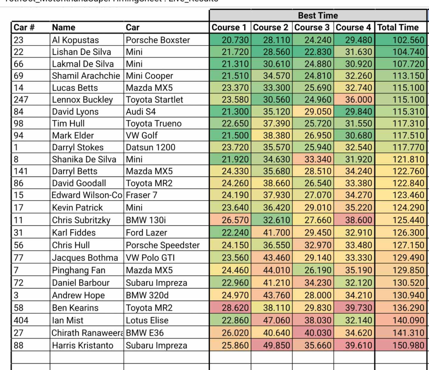
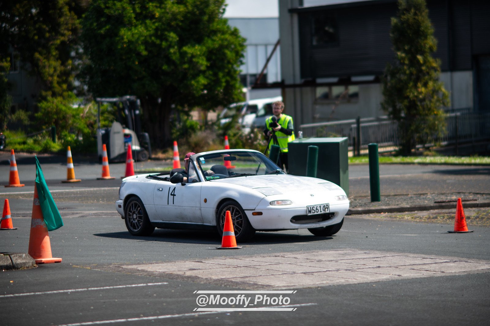
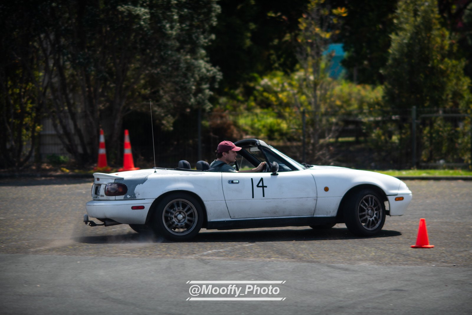
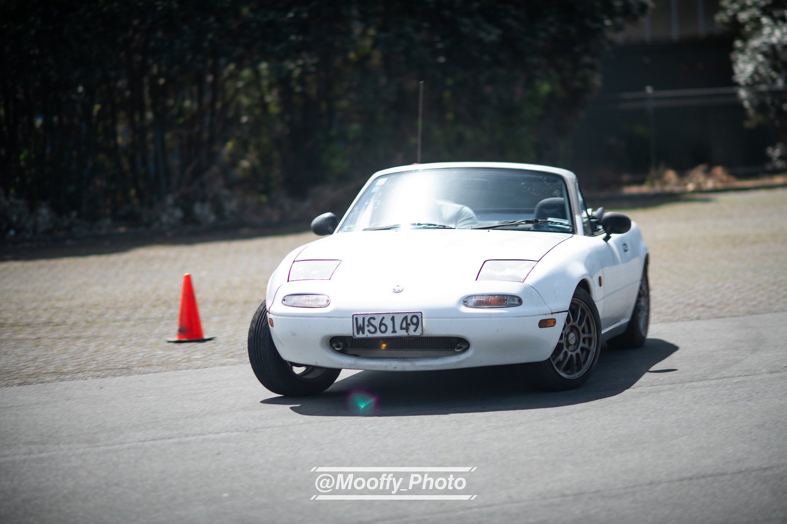
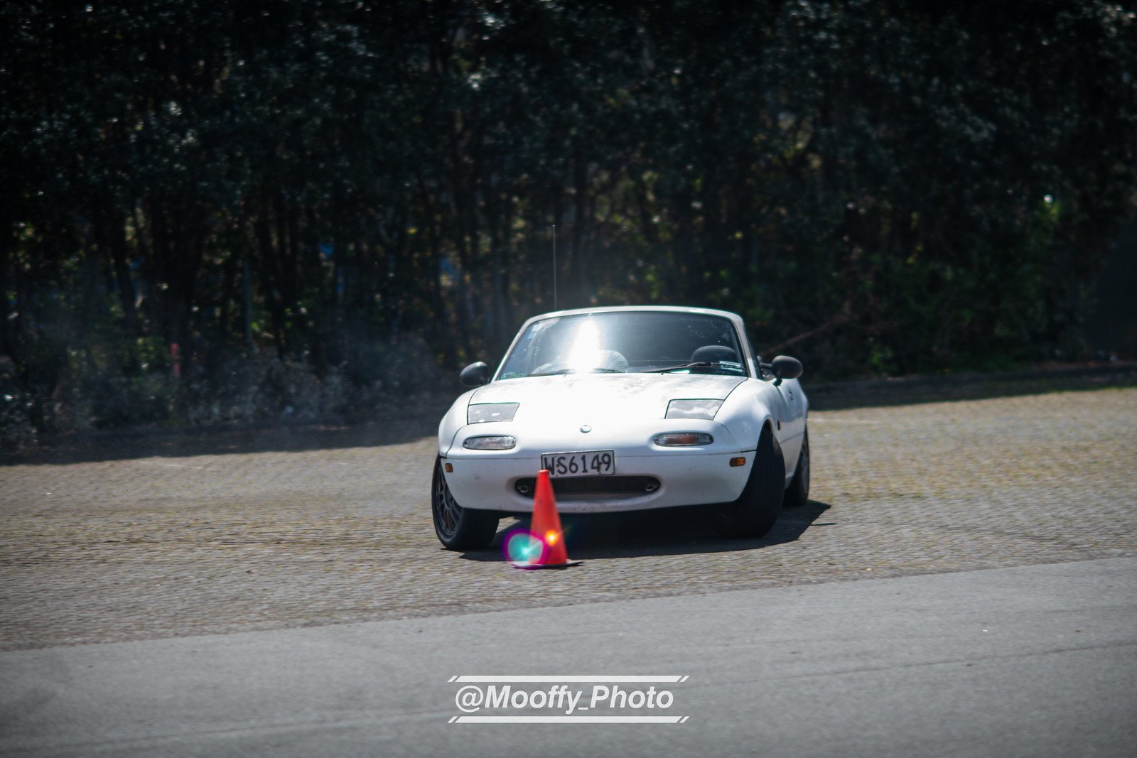
Okay so the handbrake is still NFG but the brakes themselves are awesome. It's probably just having fresh fluid and non glazed pads but the brakes feel far more linear to lockup, whereas before they didn't do much until the fronts just completely locked up. (I didn't hit that cone, somehow) I did a sccnz motorkhana yesterday (Sunday), placing 5th overall which I'm stoked about! I think the bigger cars struggled on some of the tight courses and I'm sure it would be a different story in an autocross. My dad also drove my car earning a very respectable 12th place in what might have been his very first time trying to drive a car with more than 20% throttle! Someone also took a video of my slower run of the fourth course: https://drive.google.com/file/d/1aCg9DYelcsQd_GZSELs4I_Cb2tV9oiOn/view?usp=drivesdk Still need $$ for further car improvements. Up "next" are new equal length headers and probably replace the muffler as I am now pretty sure the combination of my crap unequal-length headers and a cheap muffler are causing the last of the tinnyness in the exhaust note. Then I'll need to replace my suspension, the car still behaves very soft even with the dampers set as firm as they will go. Photo from @mooffy_photo (@mooffy_photov2 on insta)
-
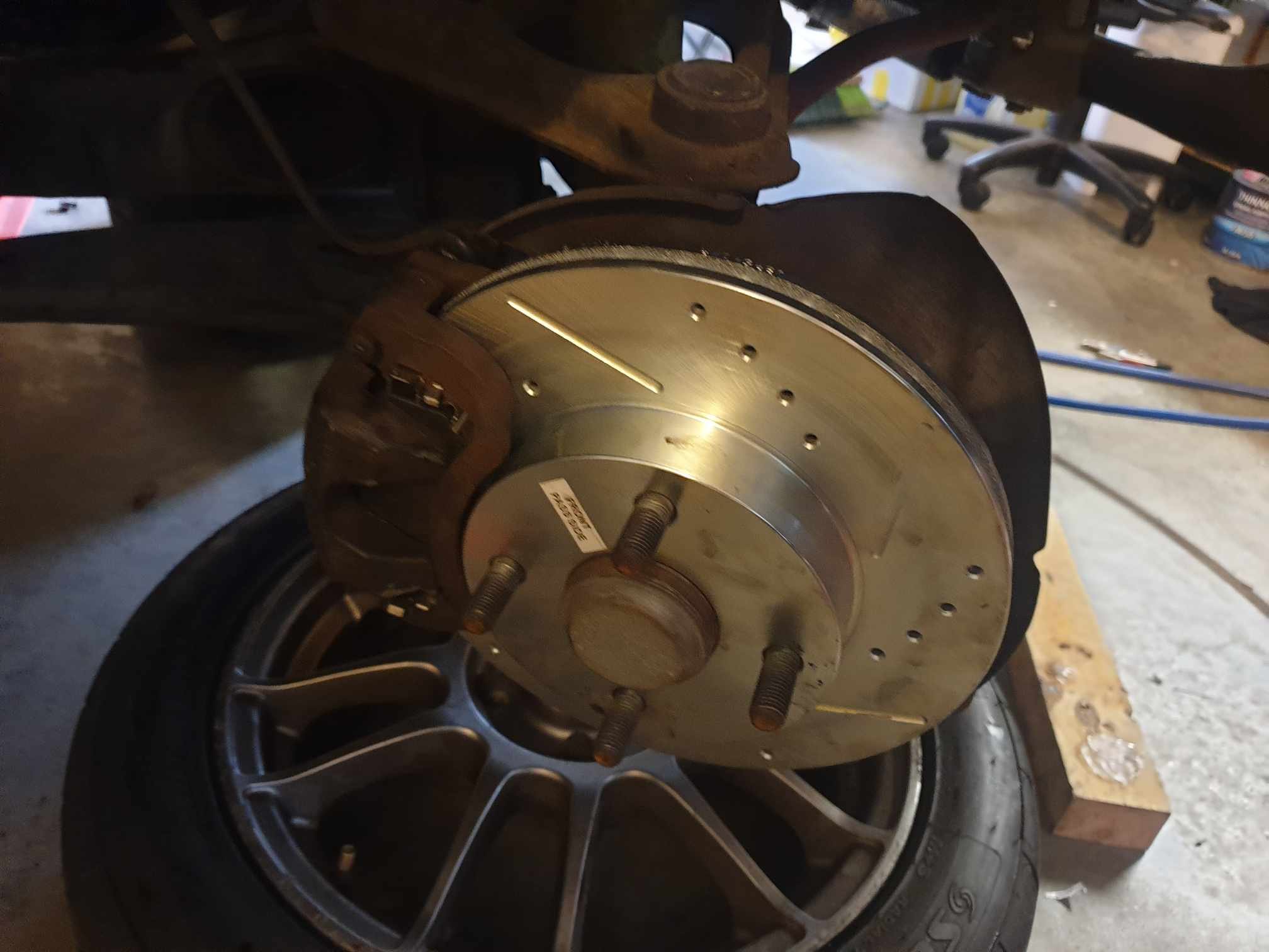
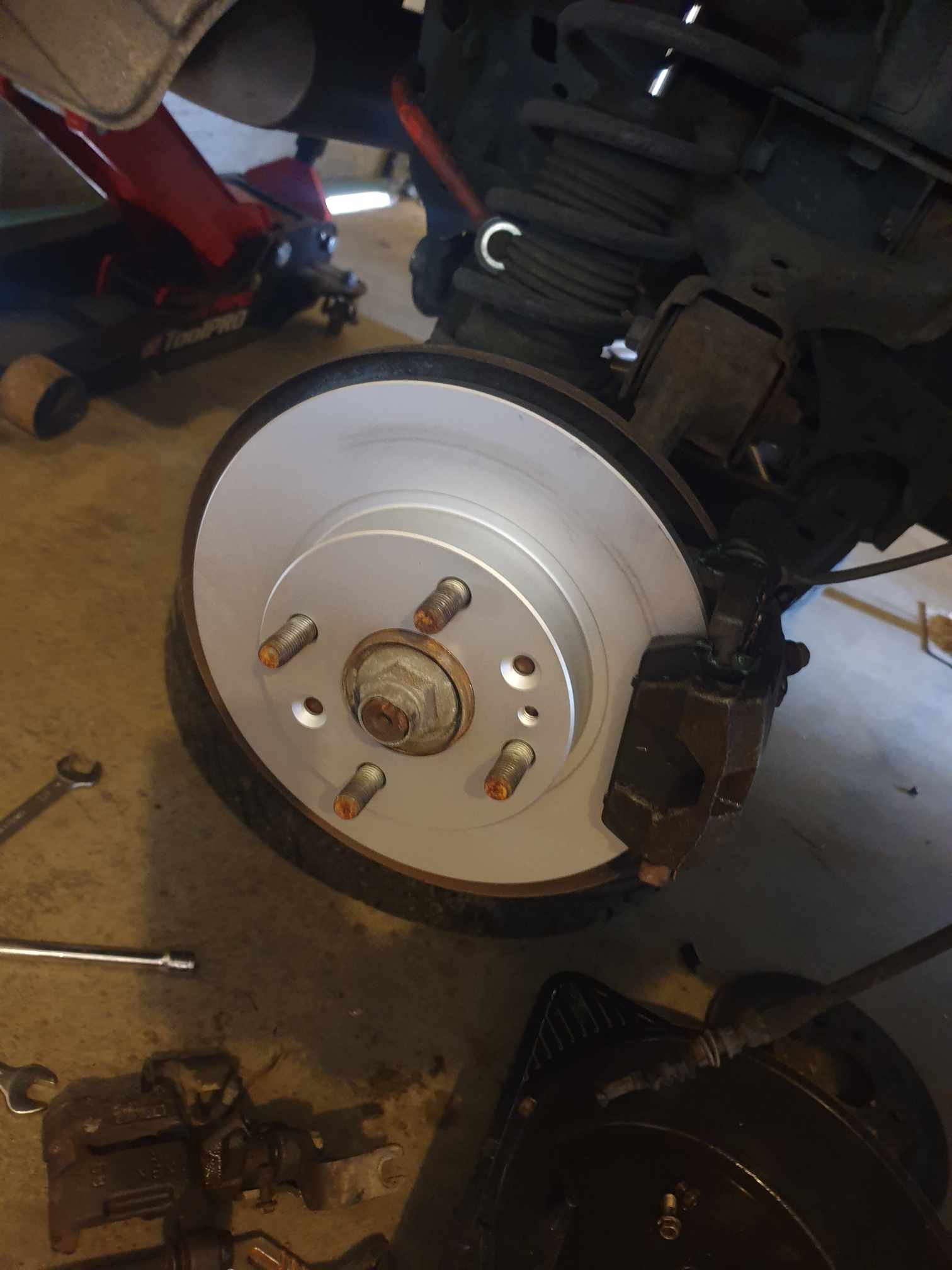
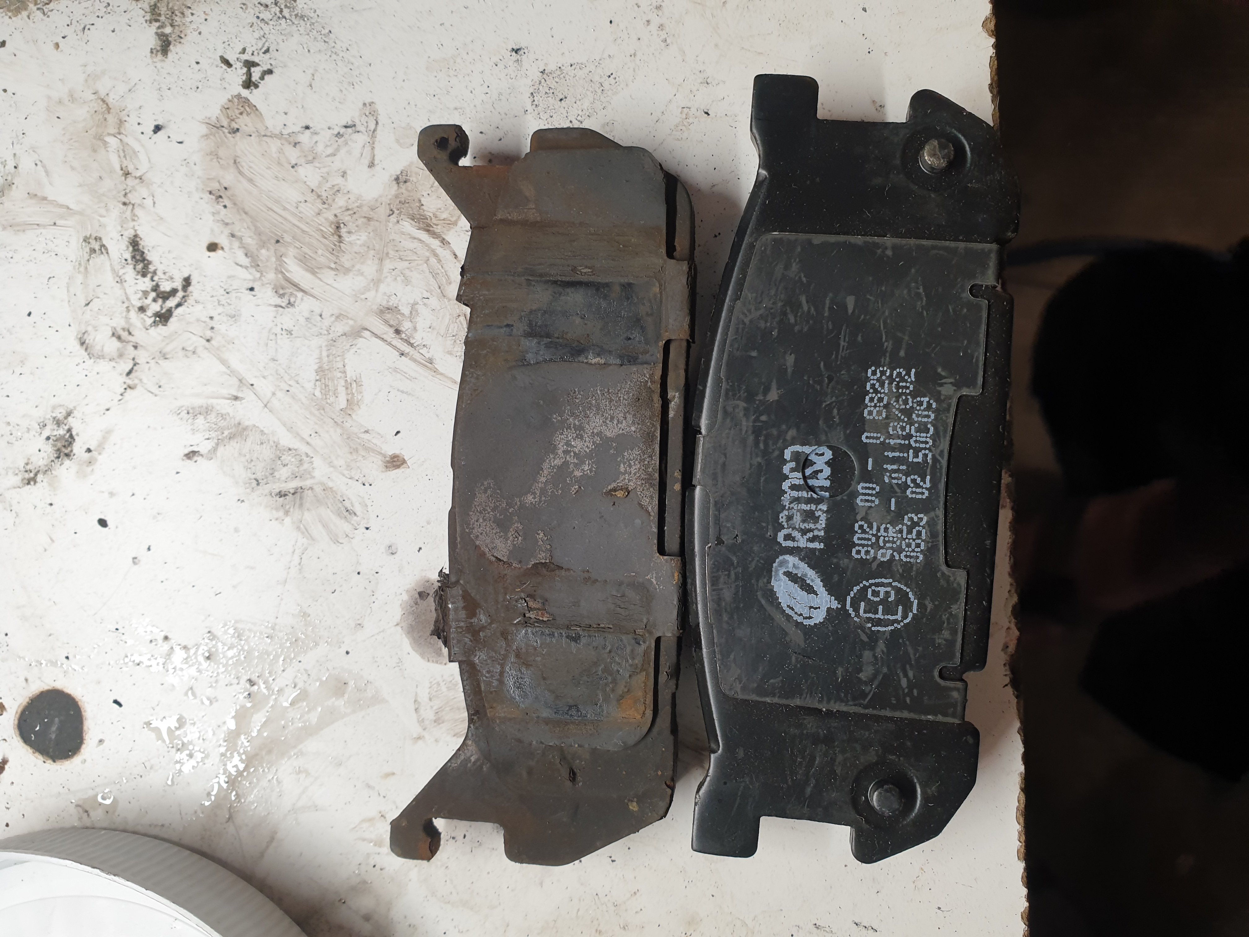
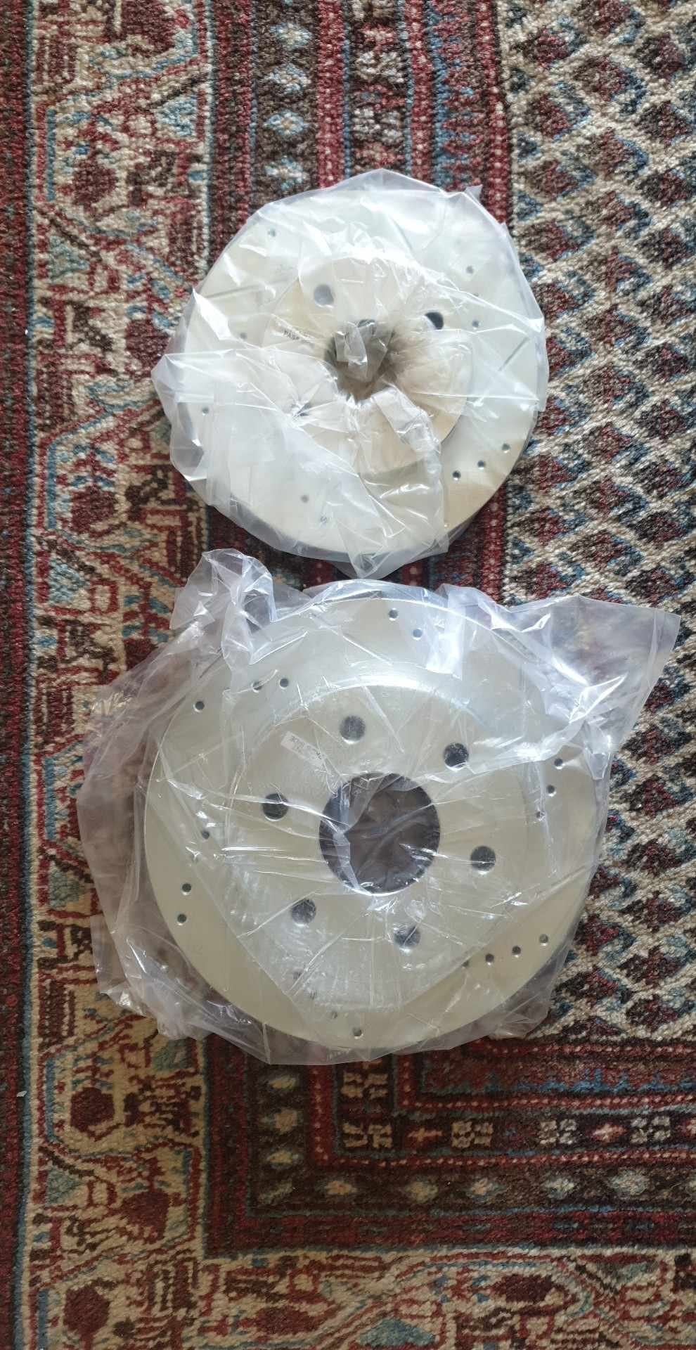
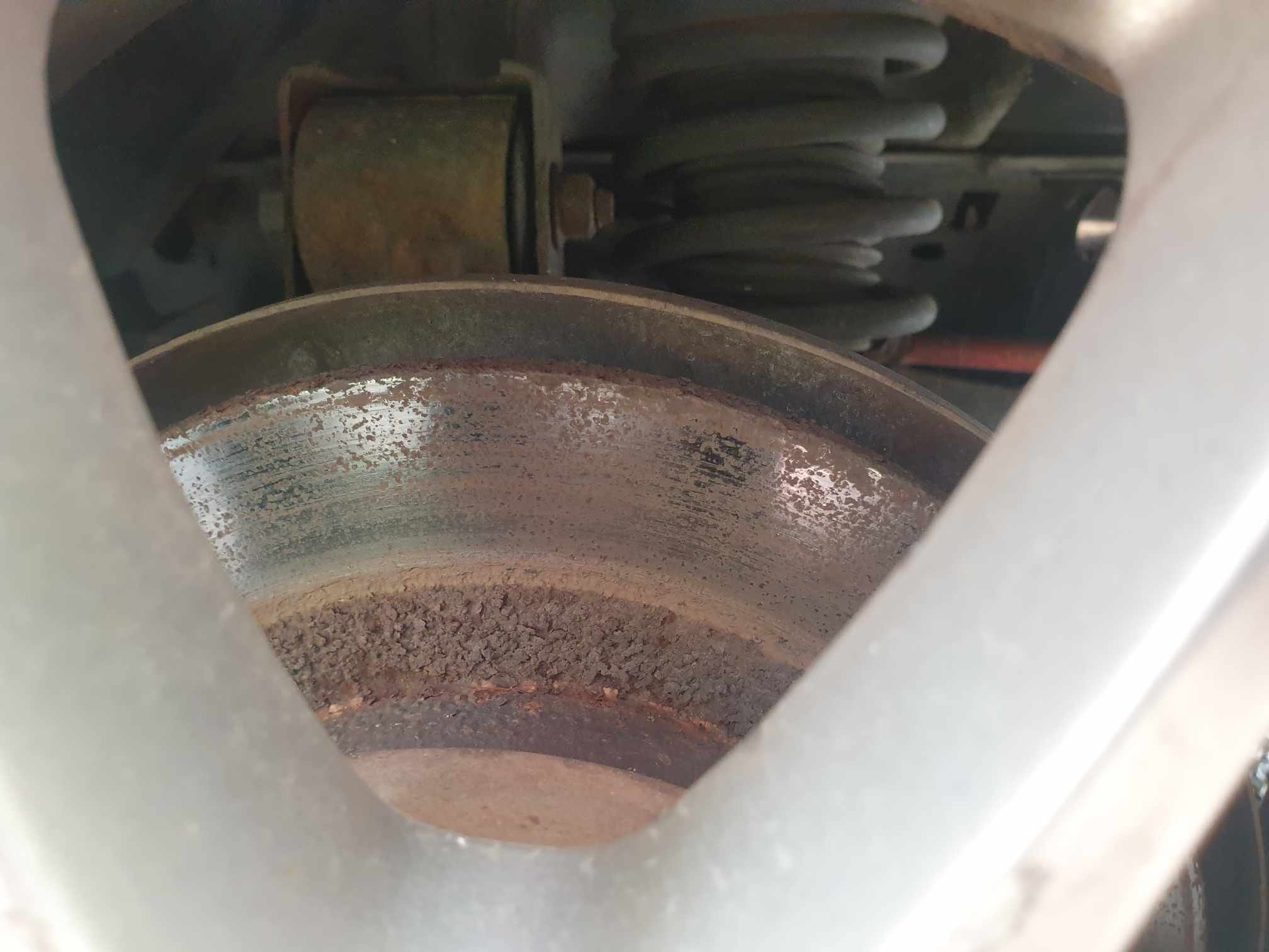
My mx5 is not 6lug nor does does it have a big brake kit, so the arrival of GMC sierra/Chevy avalanche/Cadillac Escalade front rotors for the rear of my mx5 was a bit of a shock. Rockauto was good about the refund and I guess I now own some shiny wall ornaments. The fronts and front pads arrived just fine, but rear pads were gifts from a friend but are also incorrect (nb). I want a refund on those too... Anyway NZbrakeco sorted out some rear rotors overnight and BNT had some nice pads for the rear so now the brakes are all pretty much done. Just need to mess with the handbrake adjustment points and check everything is okay (cable isn't stretching or frayed etc). And yeah drilled/slotted aren't necessary for me nor are they as "good" as plane Jane vented rotors, but I think they look cool and they were on special, so cost about the same as any other coated vented rotors. Edit to point out the crustiness of my old rears, and the reason I wanted to replace them:
-
My hopes were up Nah I was pretty convinced that it wouldn't help my handbrake, but I know my fluid is bad and I'm sure my adjusters are unhappy, so this is a good thing. I'll probably try get new discs all around and new pads too. Actually thinking back I believe at the last wof I can remember that was at a place with a brake machine, my rear balance was out of wack anyway... oops
-
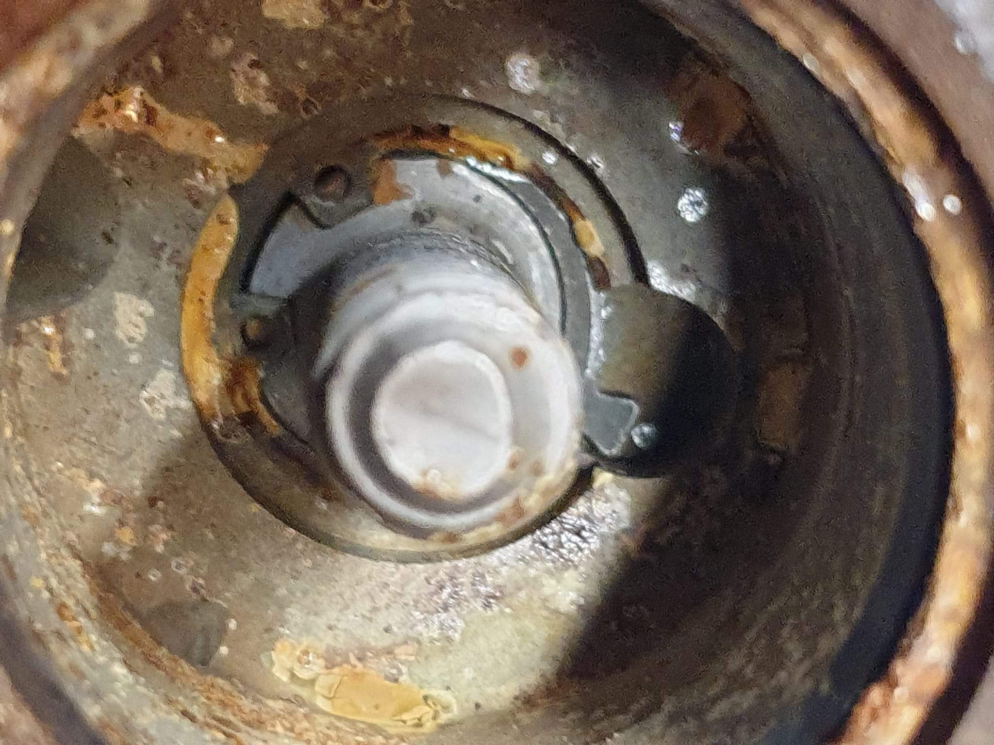
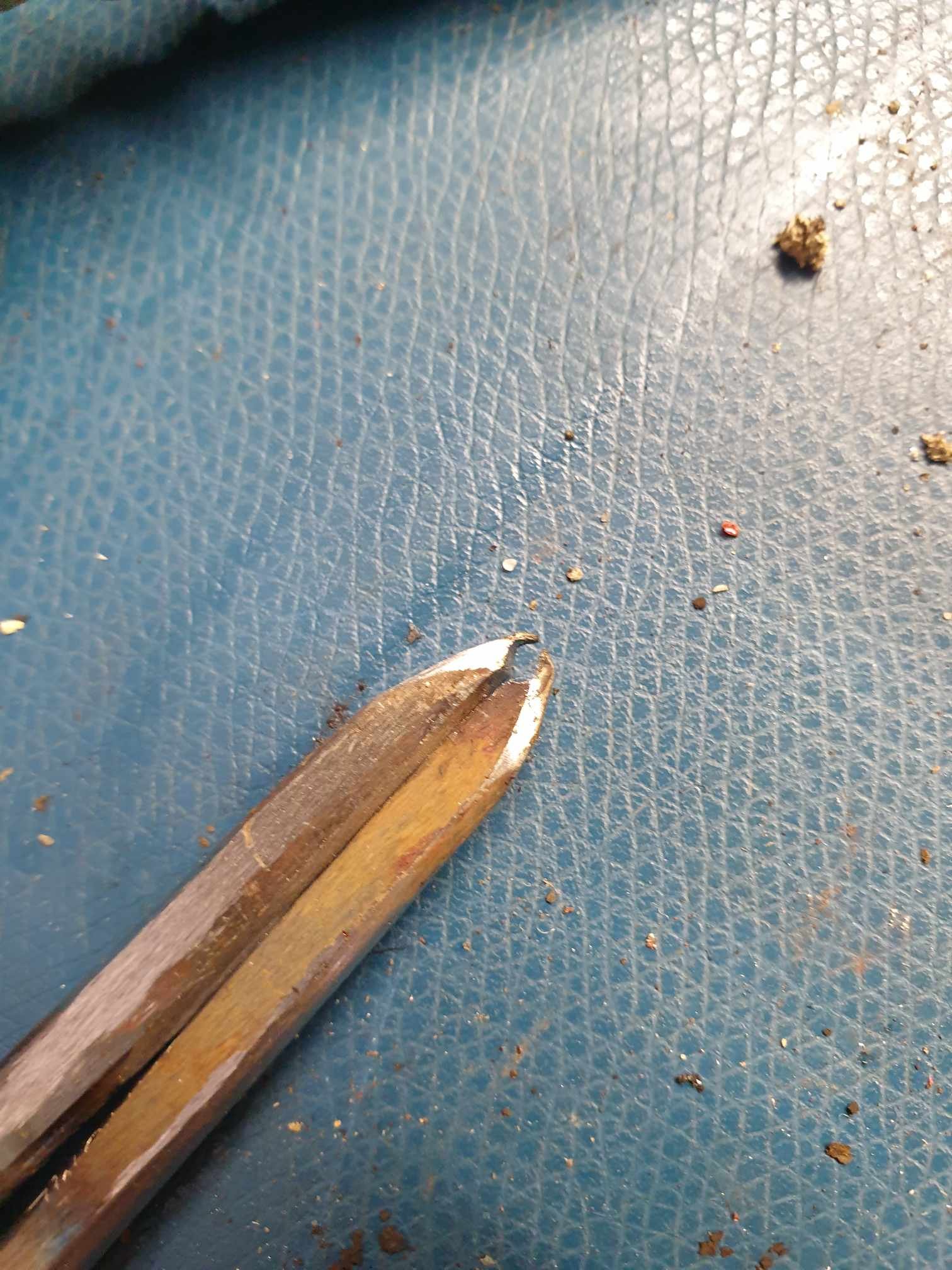
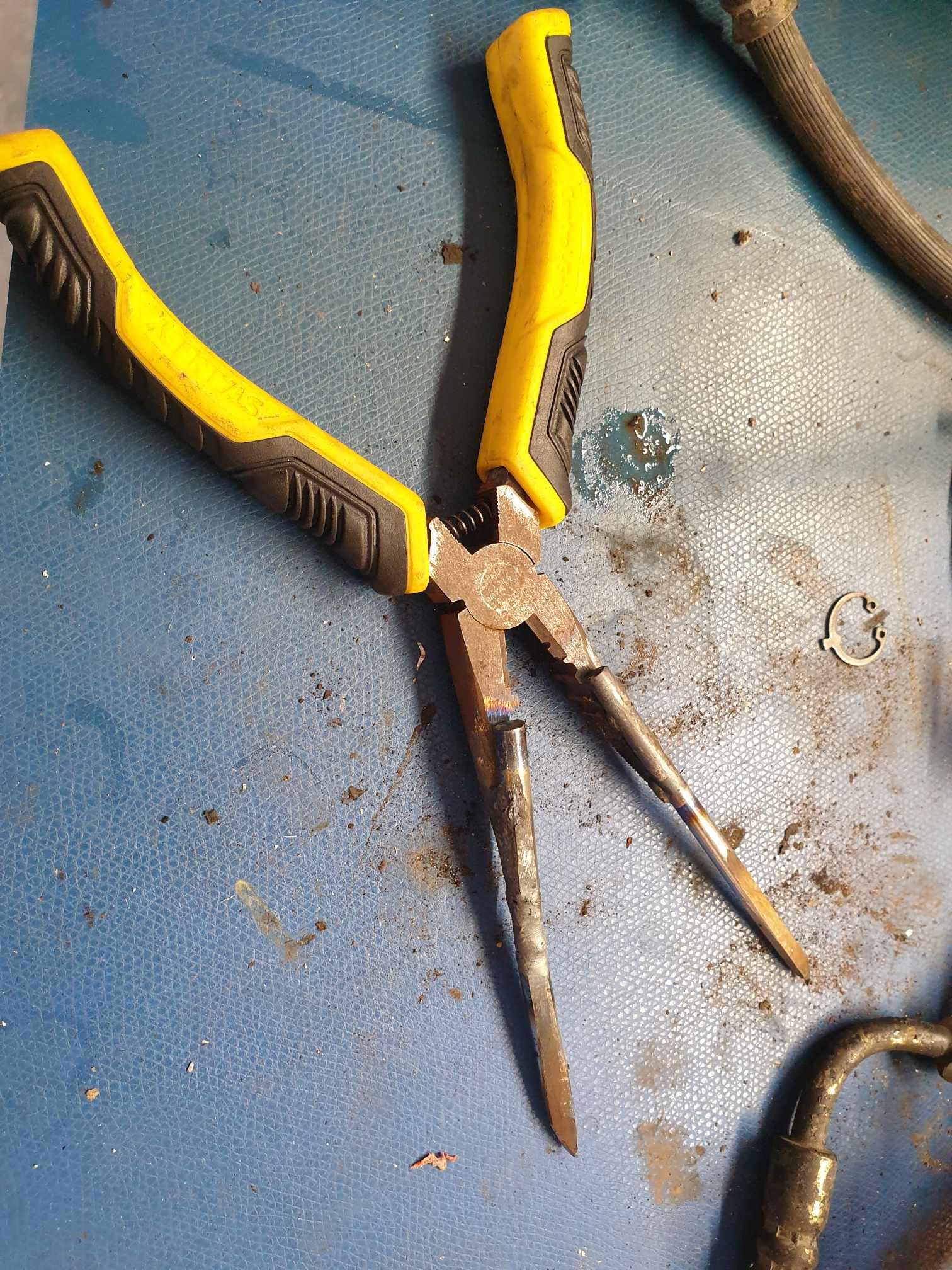
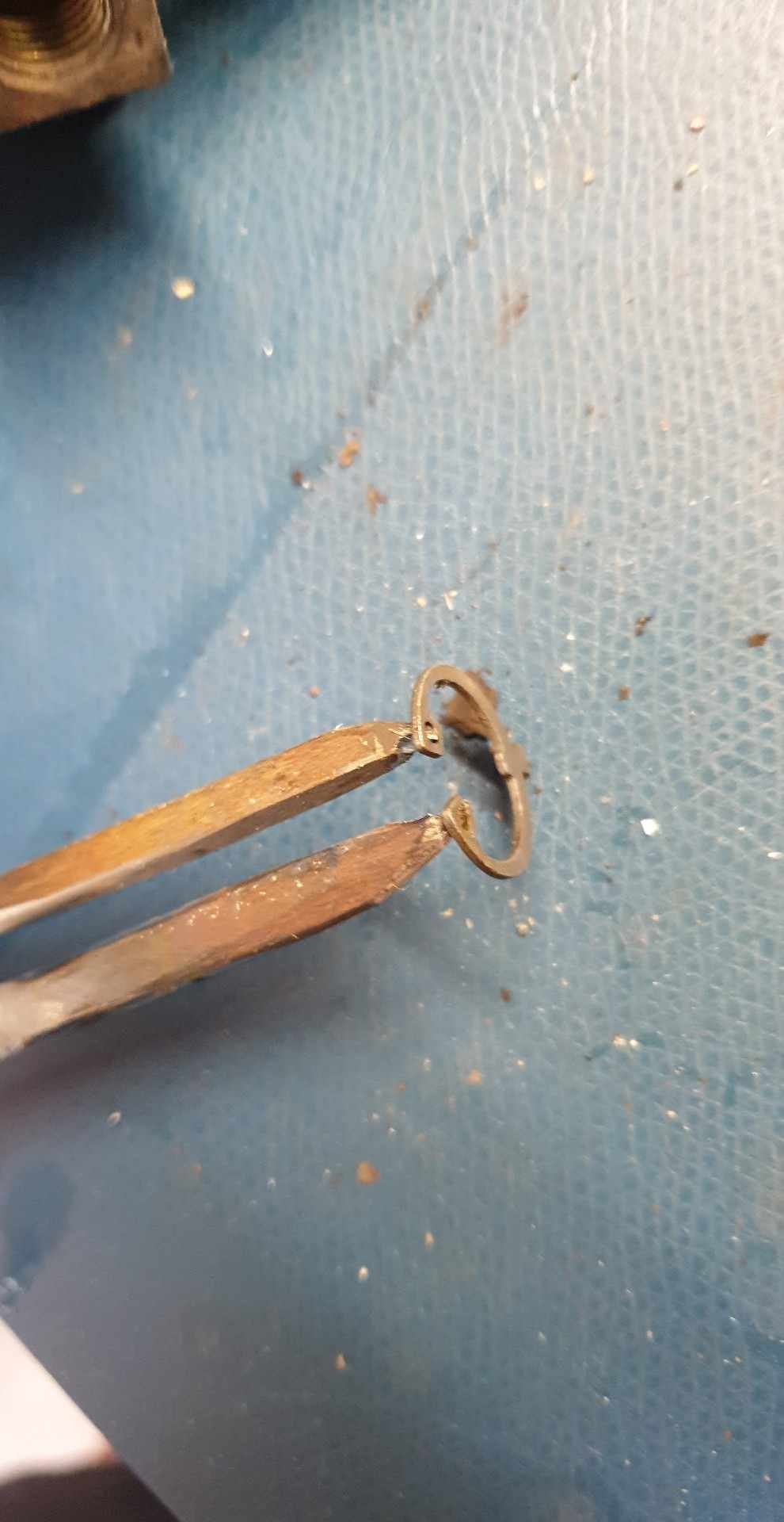
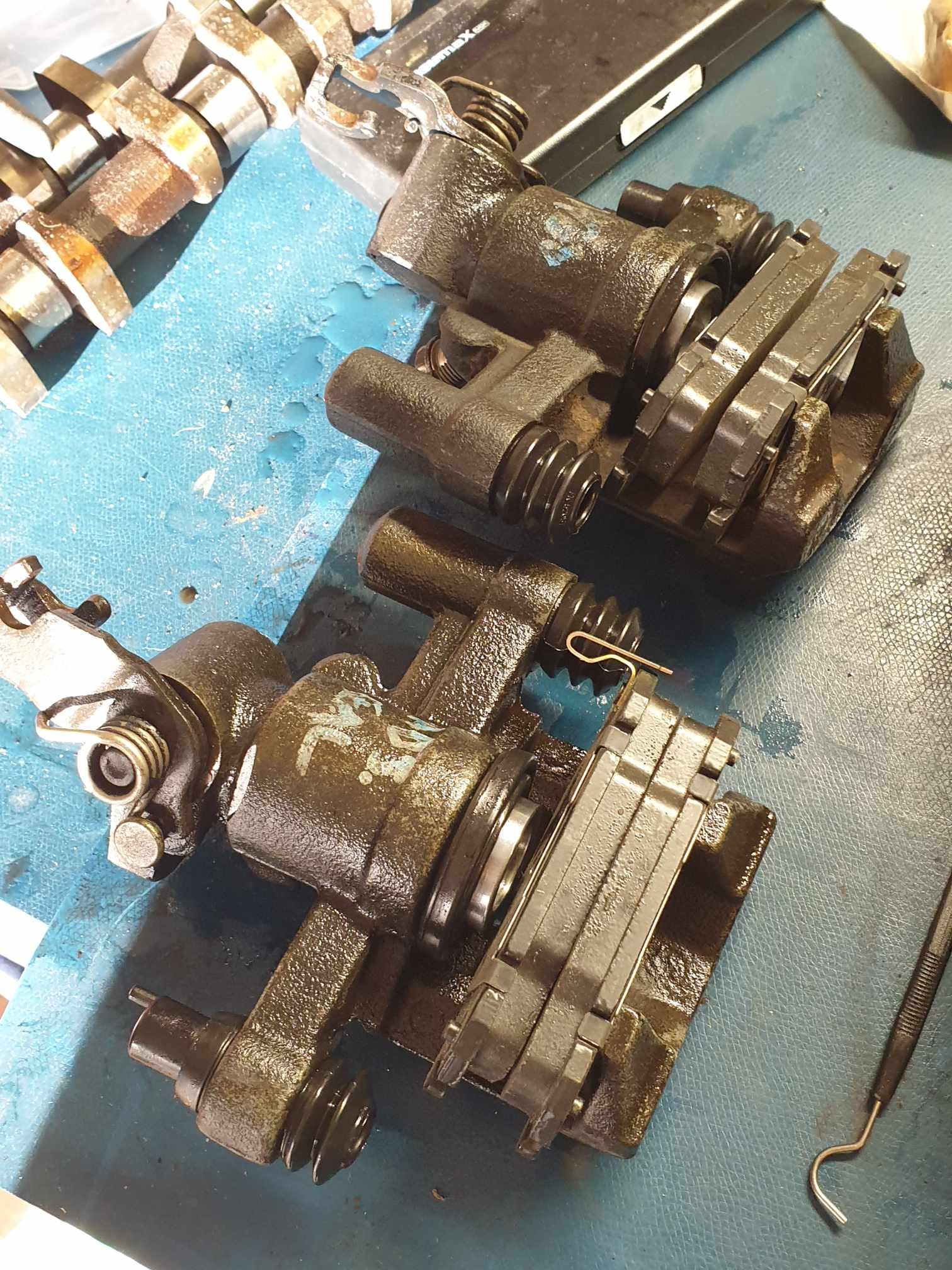
Completely unrelated to any important task at hand, but I've found a box of calipers that "we" gave up on a few years ago, and started working on them again. The fronts were already reassembled, rears have a painful circlip around the piston adjuster mechanism. They're down the back of the bore and really difficult to get at, so I had to make some ultra long circlip pliers. I don't think this ranks in the top-50 on the list of sketchiest things I've done. It did however get the job done, so now I have some rebuilt rear and front calipers to go on my car. I'm hoping this will help with my non-existant handbrake before the next motorkhana in mid October. Also my car is probably far overdue for new brake fluid and I can now kill 2 birds with 1 stone.
-
I'll get to the "current" exhaust video one day - however these are before videos of the old setup (bad intake, shit resonator) at a motorkhana held by SCCNZ in march. Not the tidiest I don't think this course was meant to have a loop Cue excuses: no handbrake, no power steering, no abs, bad driver The reason I have few/no "current" videos is that I have this annoying "chirp" at mid throttle: it sounds like the intakes are whistling? I believe I need to take my intake off and really smooth down all intake surfaces so there are no lips/edges for air to flow over and make noise, because it is super frustrating to drive like that. It also makes cruising super frustrating because most gentle inclines cause the chirping noise again. I'm also going to get a new rear muffler, I think my current one is fine but I want something that reduces the total exhaust volume significantly, as it is a bit loud at motorway speeds, reducing the top-down comfort I'm expecting to need this summer. Gratuitous overrun on the way to a meet in Tauranga.
-
Apologies if it has been discussed already in the last 17 pages but a quick ctrl+f didn't find it. Regarding DBW control - RusEFI boards have open source DBW hardware and firmware available for you to look at. I mean I'd suggest getting some proteus boards manufactured (including 2 for me ) however component shortages are a right pain. The Proteus handles dual-DBW so the hardware/schematic could be taken from that repo, and to control it perhaps picking apart the rusefi firmware would be the way to go. https://github.com/rusefi/rusefi/blob/master/firmware/controllers/actuators/electronic_throttle.cpp https://github.com/mck1117/proteus
-
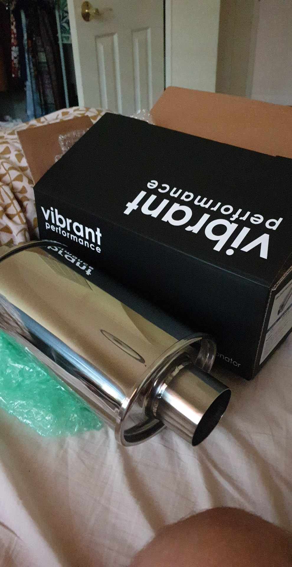
Alright Friday night shenanigans. Im making the drive to Tauranga on Sunday and it's time to remove the drone and rasp from my exhaust. Previously I had the absolute cheapest stainless resonator I could find but I splurged for a Vibrant Ultra Quiet 2.5" resonator to replace that. I ordered it late last night, arrived today and I was very happy (jump scare face reveal included). And yeah. The money shot: Some late night welding: And the old resonator: New one welded on: And the end result... Well it's not ultra quiet, but it has none of the old farty rasp that my exhaust used to have. Finally an NA setup that doesn't sound like trash! I really like the new sound. Growl and bite but no bark. Ready for a good weekend! Oh and I got a wof, with a few minor suggestions...
-
The suggestion given to me last wof was to tidy the front bumper mount and tow hook points. I did that, plus tidied the front sills and most of the engine bay. Its amazing how much the engine looks more at home in a halfway tidy engine bay! I'm also reassembling the interior and tidying up the guards and front bumper a bit before final reassembly. Should be able to take it for a shakedown soon to see how the intake behaves, then hopefully wof this week. Meet in Tauranga next weekend so I'm hoping for a pass first try... (Broke a lamp...)
-
Are you at all concerned with the "modified" section at the back? Lol
-
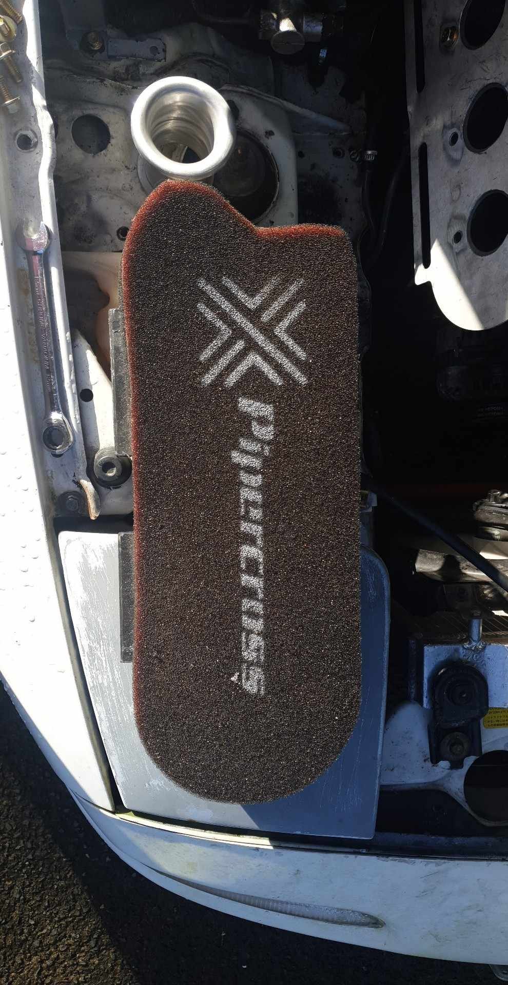
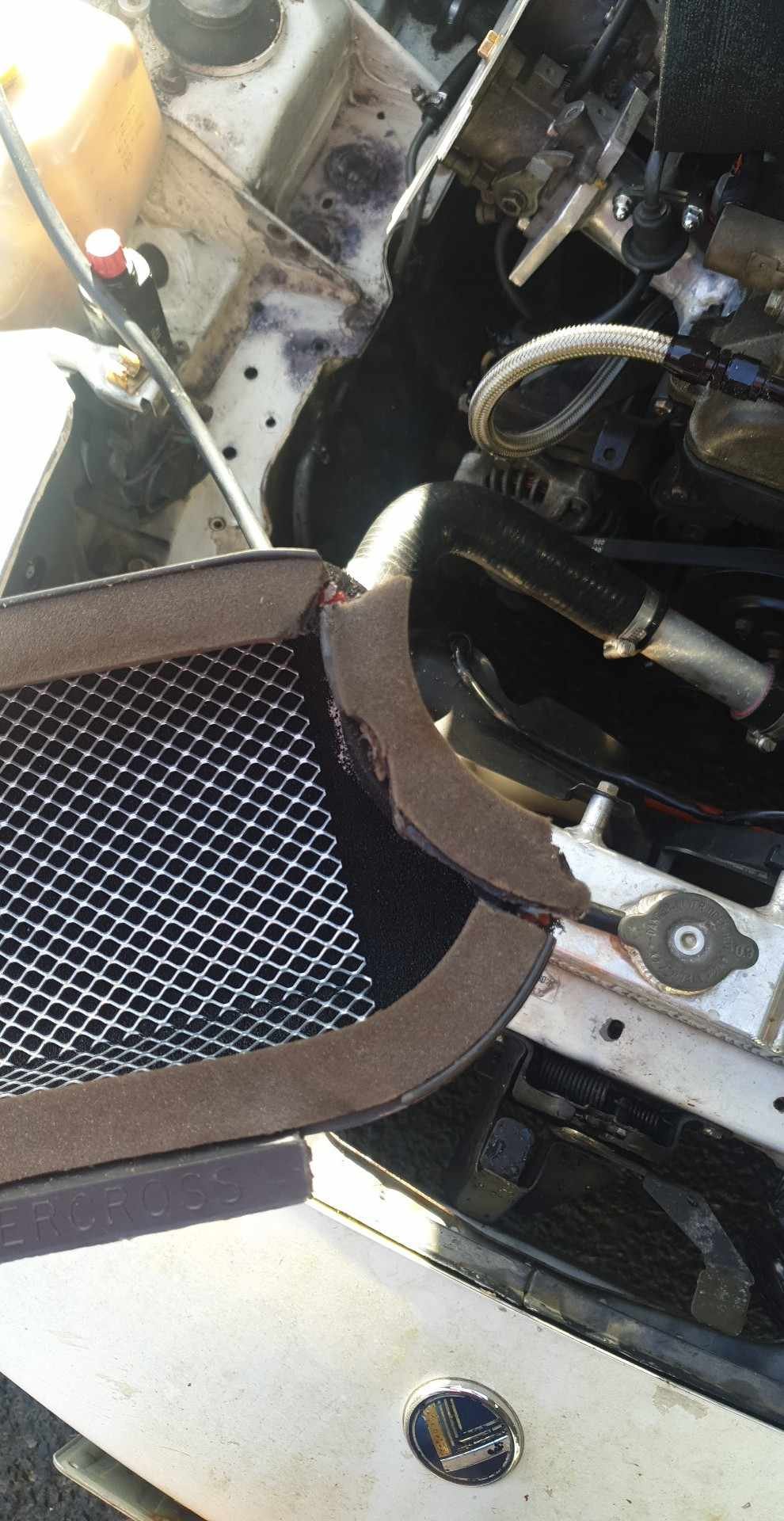
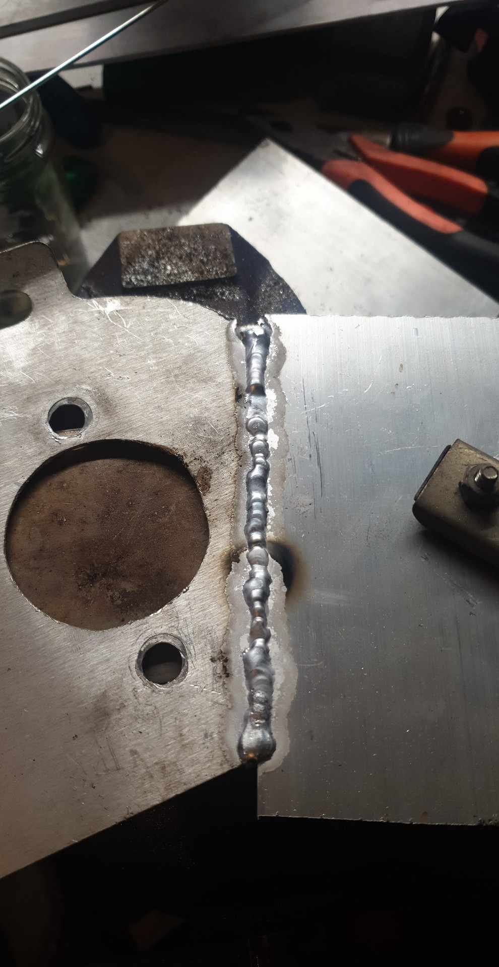
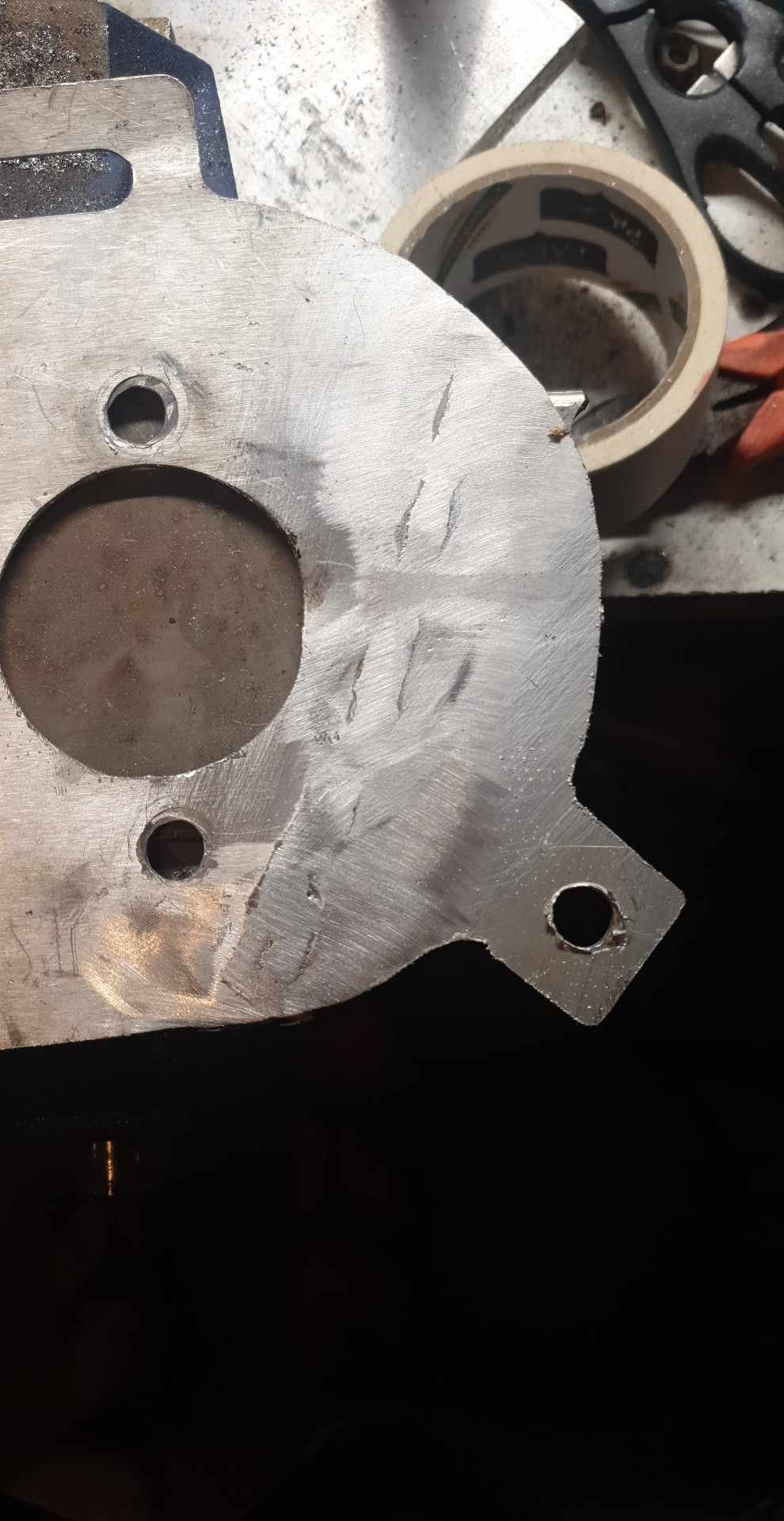
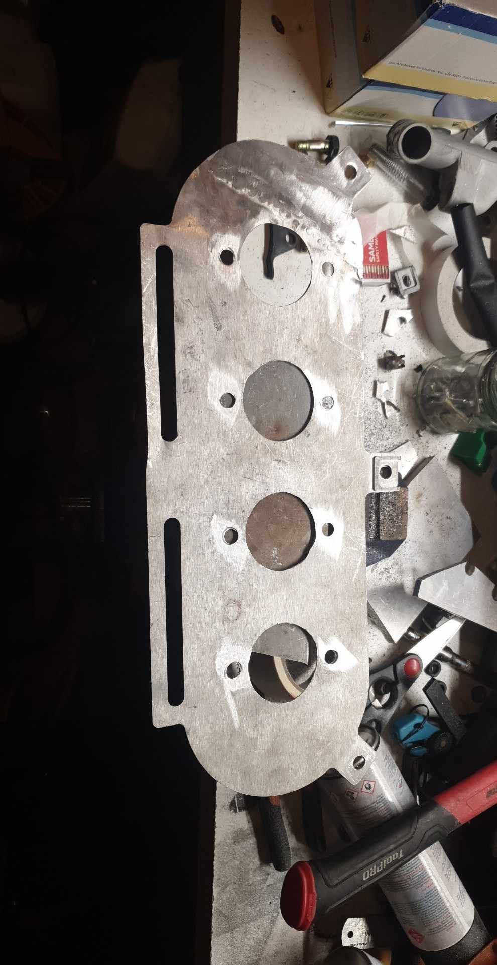
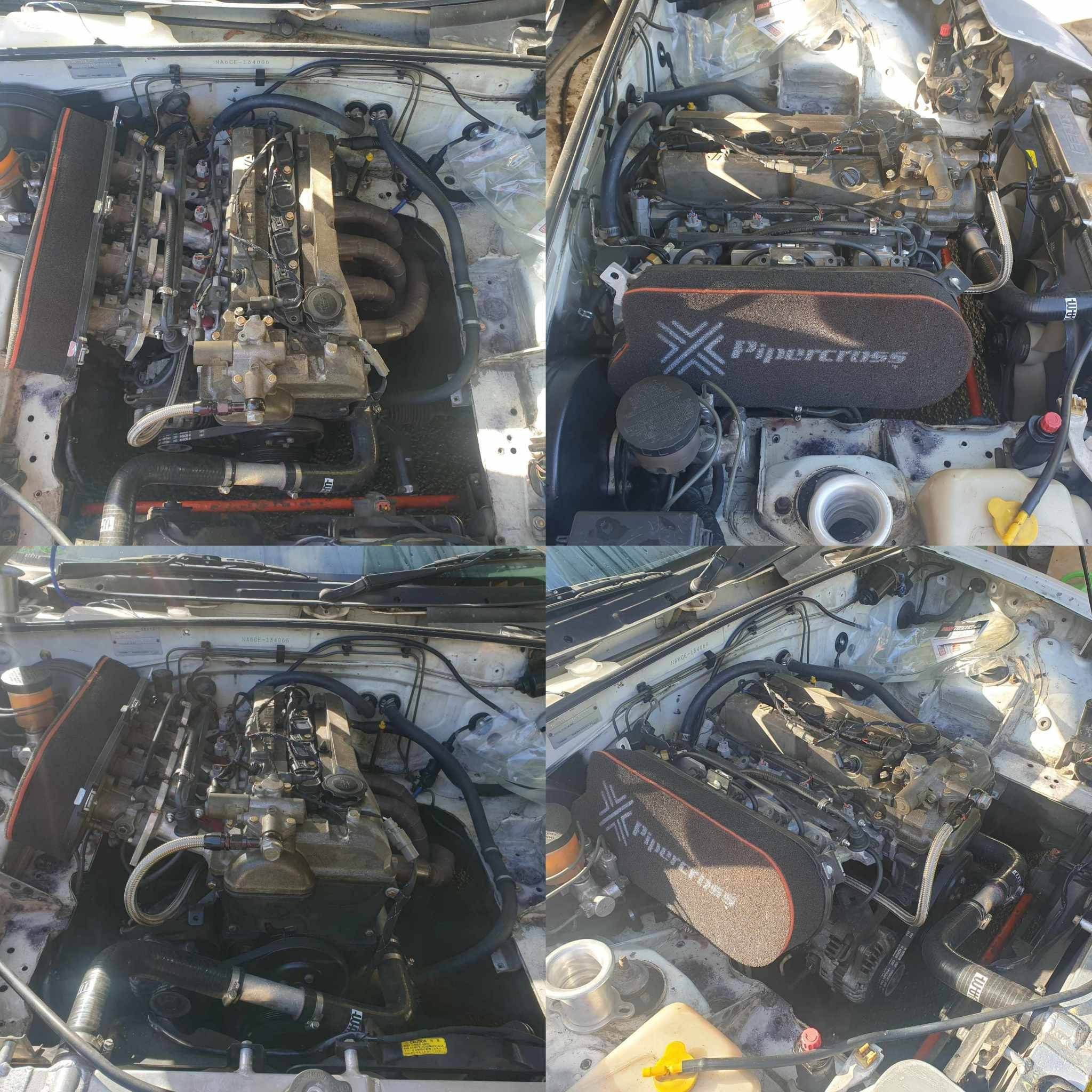
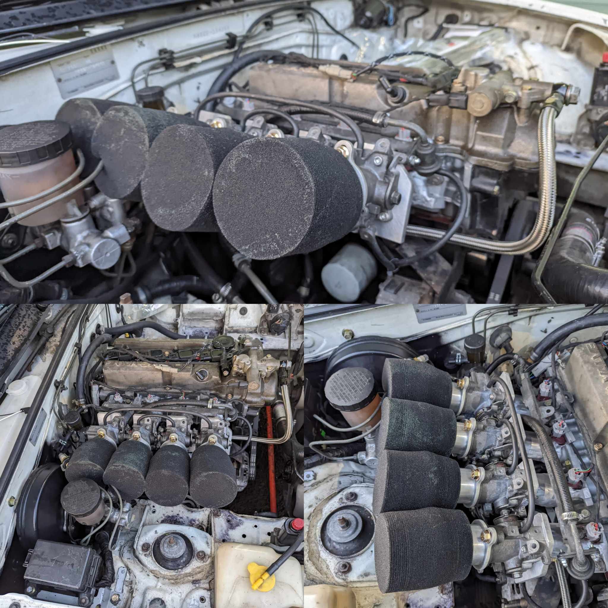
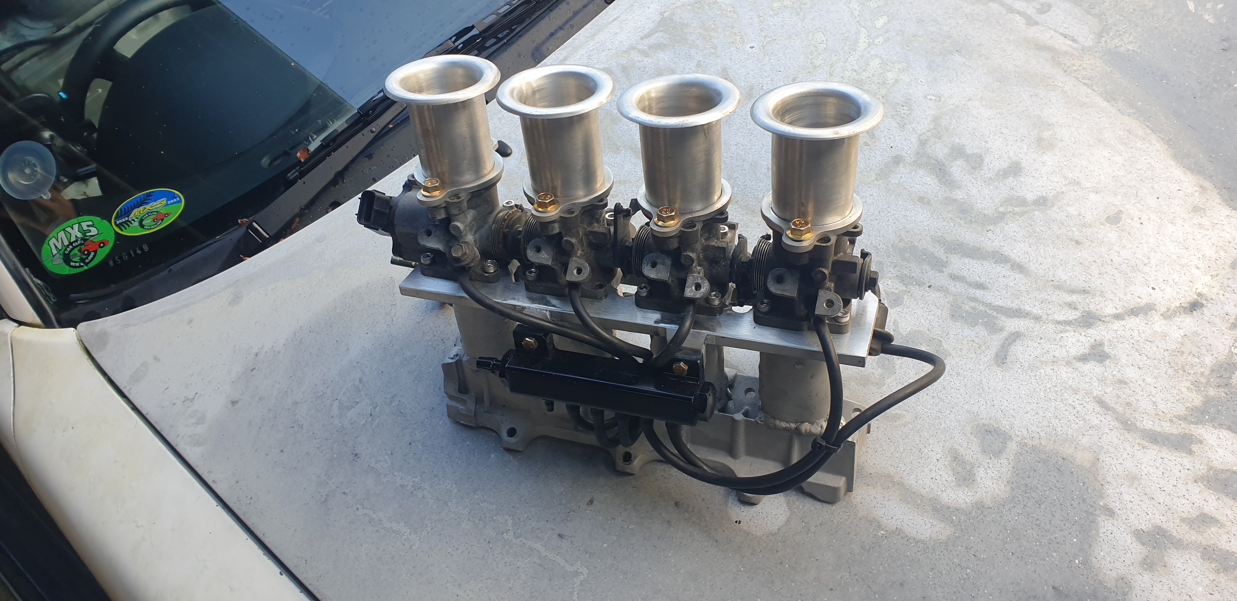
Alright air filter time. Bare trumpets are cool, but every bit of roadworks or loose surface scares the shit out of me. I don't have an engine undertray so rocks are a very real concern! Some cheap filter socks came up which fit great. I don't mind the look, but they are very restrictive for airflow. A friend had an ITB'd BP on the Dyno and gained 10kW removing his socks, so they aren't excellent for performance. Some may have seen that I used to have a pipercross px600 box air filter, which I had modified to clear the clutch slave in my old setup. Well I wanted to un-modify the backing plate to save money, and possibly eventually replace the box filter with an unmolested one. I welded a new plate on where I cut earlier, then ground it flat and cut the shape up. Now I have to replace the box filter but we have option number 3: a badass box filter setup. My trumpets don't fit under this filter and the filter is a bit hacked up at the back, however I love the look. Soo yeah, filters are cool but the box one will prove expensive. I'm not sure what option I'll settle with but if anyone has any thoughts (or a cheep box 80mm or domed 120mm px600 filter) let me know!
-
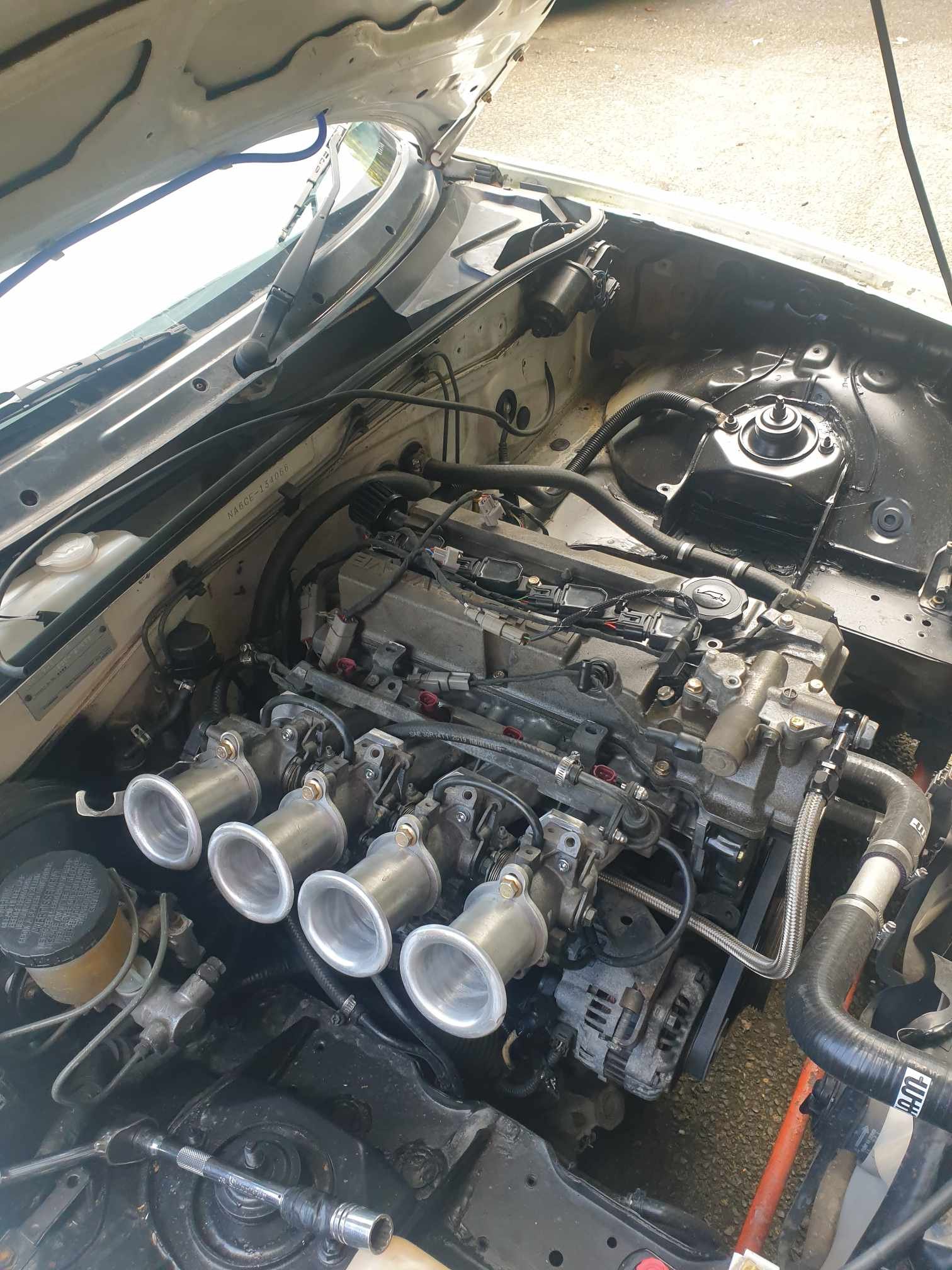
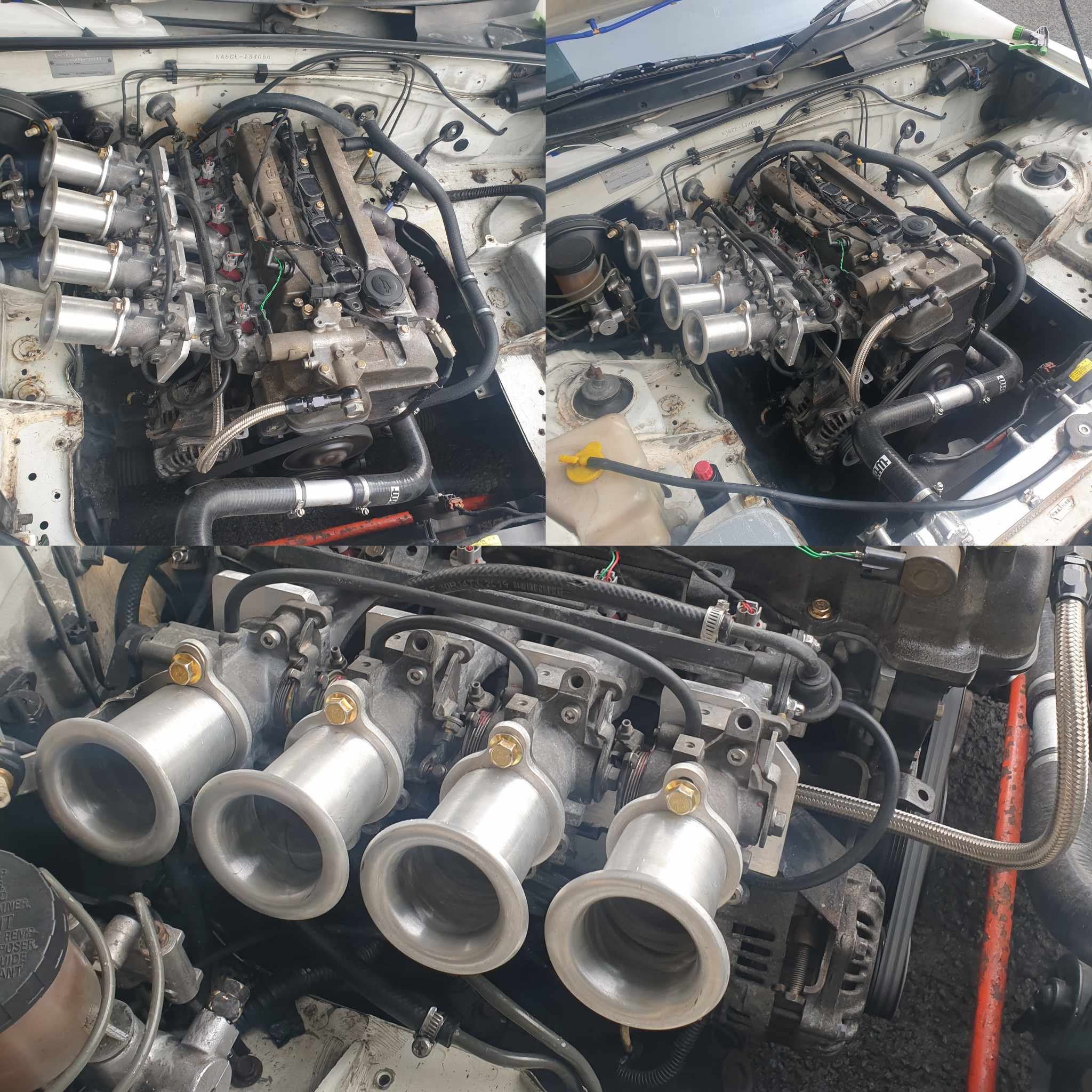
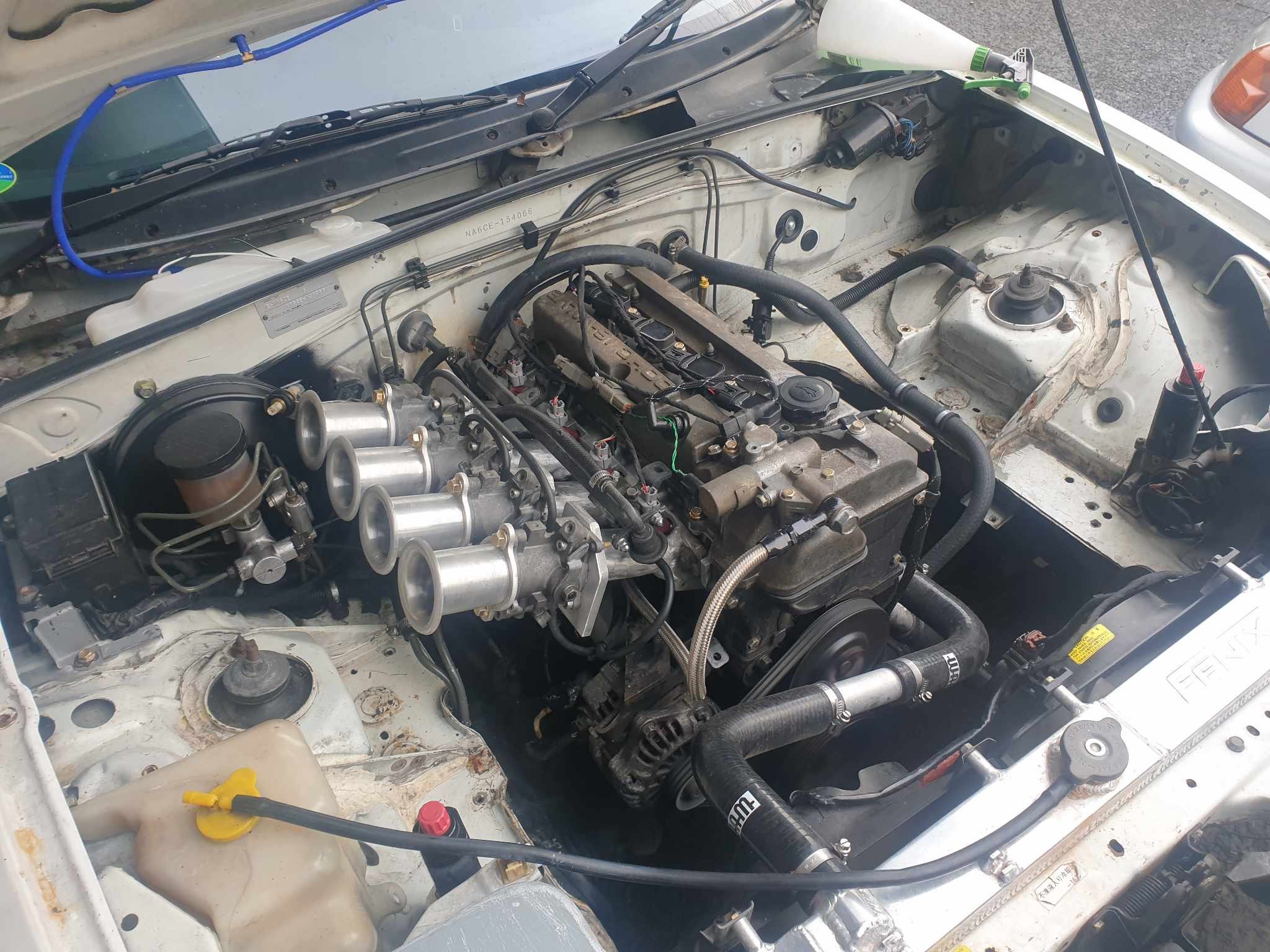
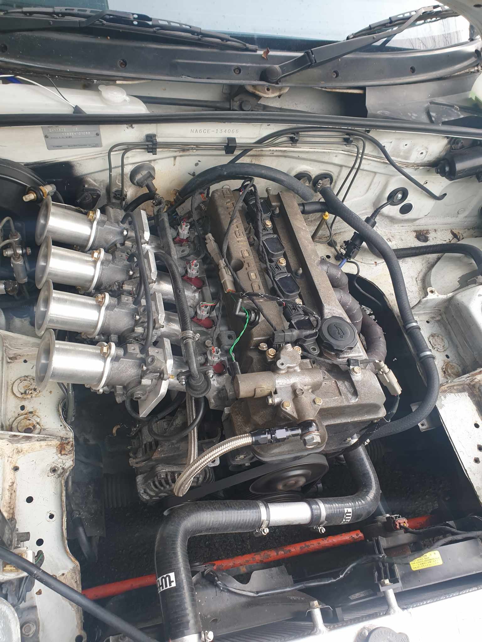
Lights out and away we go, the new manifold is on. I had to flip my brake booster to clear the trumpets, painted it again at the same time to tidy it up. Also I had 10,000 vacuum leaks. Turns out my aluminium welds are just as shit as ever, thick casting doesn't help my problems. Eventually I noticed that one little bump on a weld was touching injector #3, stopping a good seal at the base of the injector. Rectifying the air leaks and solving fuel hose routing, plus a few other things done. Now the car is back to running and driving but still always more to do! Wof is expired so I'm needing to tidy up some of the gremlins that have appeared before taking it back in. Video of dorts here
- 70 replies
-
- 11
-
-
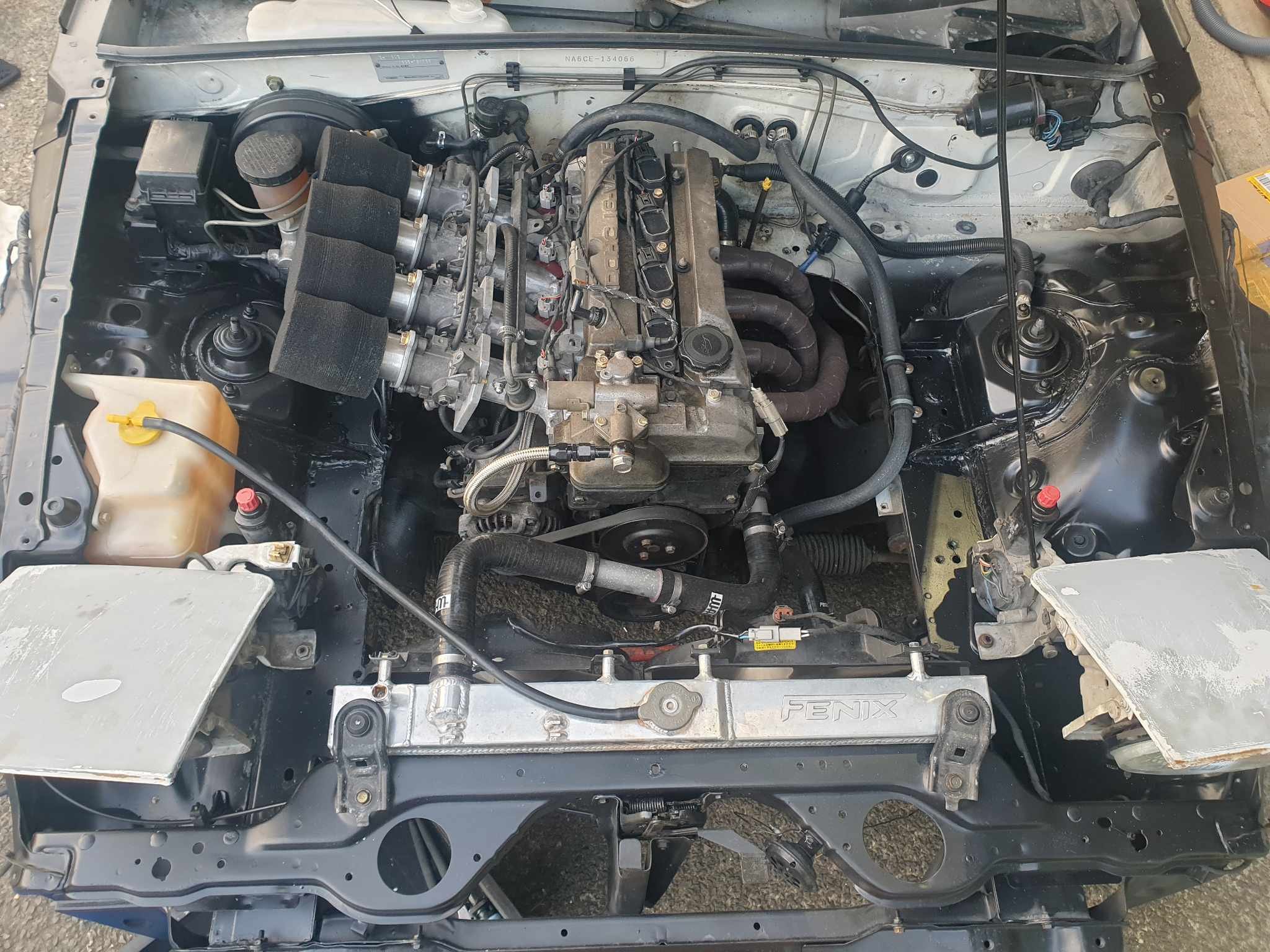
I've been busy with a major milestone at uni, which I have (un)officially completed as of Friday so I could spend the long weekend carrying on with this. I've tacked together the intake manifold. need to get some roloc pads from blackwoods to do proper surface prep before continuing as the tacks are pretty dodgy to say the least. The ZL casting is far worse than the old 4age flange I had on the old manifold, this is full of crud and loves to pop and splatter, however once new material is infused into the casting it doesn't do too badly. As I was hoping for, it clears the fuel rail, brake/clutch things and bonnet. Perfect. One day I'll get around to making a plenum for it, but for now it'll remain open to atmosphere.
-
Random slightly cool stuff you built but not worth its own thread, thread
Themi replied to h4nd's topic in Other Projects
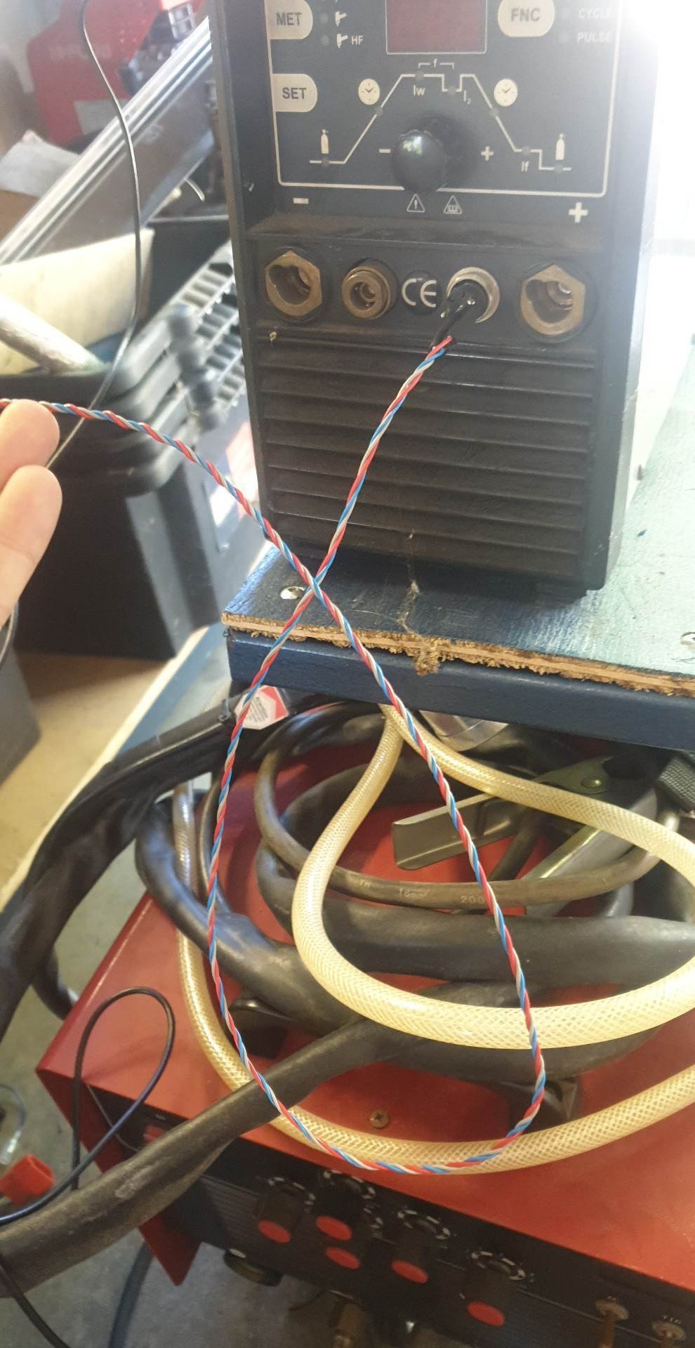
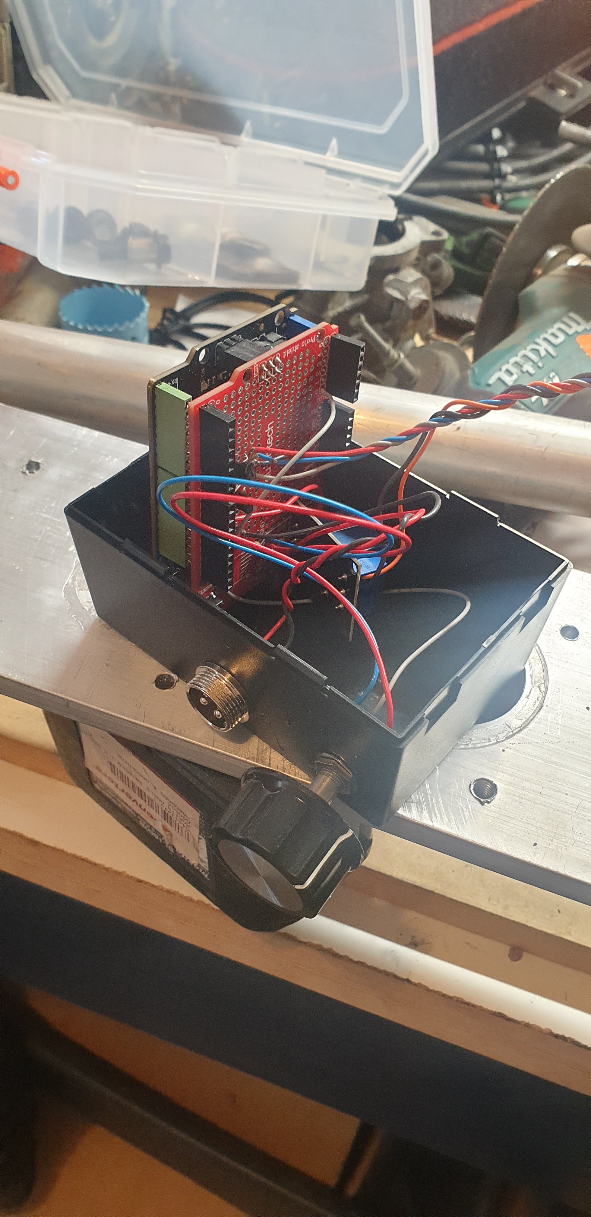
Tig foot pedal - Arduino style My smaller Tig welder doesn't support a foot pedal, just an up or down button on the torch. It doesn't really give the control needed for materials like thin stainless, so here we go... I used a knockoff Arduino uno and a cheap Jaycar protoboard. The wires headed to the welder are soldered on as the control box will be glued to the side, but the 4-pin connector is the one that will go to the foot pedal and the on/off button on the Tig torch. The pot in this case will probably be for "scaling" the foot pedal (perhaps full travel should be +/-10A, or +/-50A?). In terms of control, the three buttons for the welder (up, down and "on/off") sit on a 5v pull-up and are pulled low to activate. There are 2 ground pins in the connector. I've got up and down switched by some transistors but the on/off needed a relay as the Arduino was being reset when the argon solenoid triggered. I used a diode to control flyback but I think the solenoid plus the HF start were enough to funk-up the Arduino. Due to the debouncing in the welder buttons I found the minimum pulse duration to be 30ms and 20ms between pulses. This gives about 20 pulses per second, leading to a maximum amount of up or down per second to 20A, which should be plenty for a foot pedal. I haven't actually built the foot pedal yet but I was just thinking of attaching an arm to the potentiometer to make a linkage, and using a gate hinge + spring as the pedal itself. Real welding foot pedals are surprisingly expensive! It's not the most interesting project but it solves a pretty annoying problem...
-
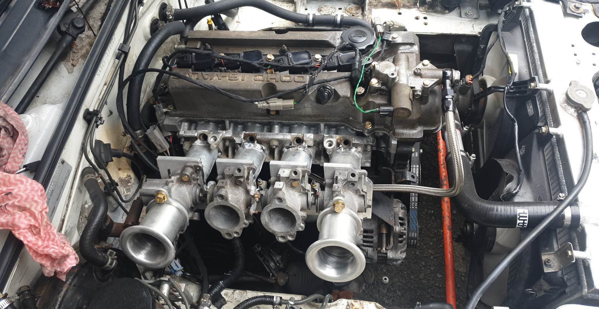
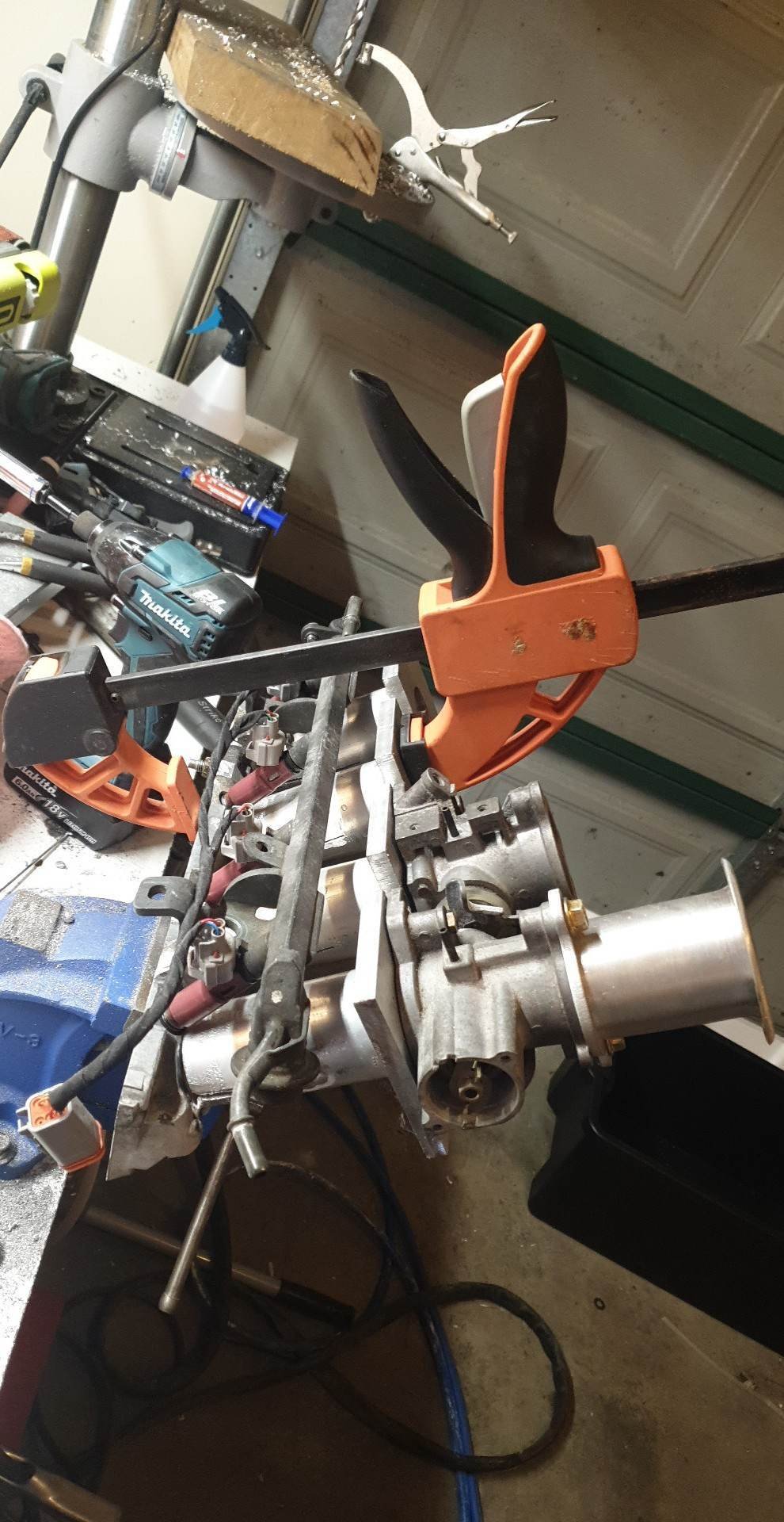
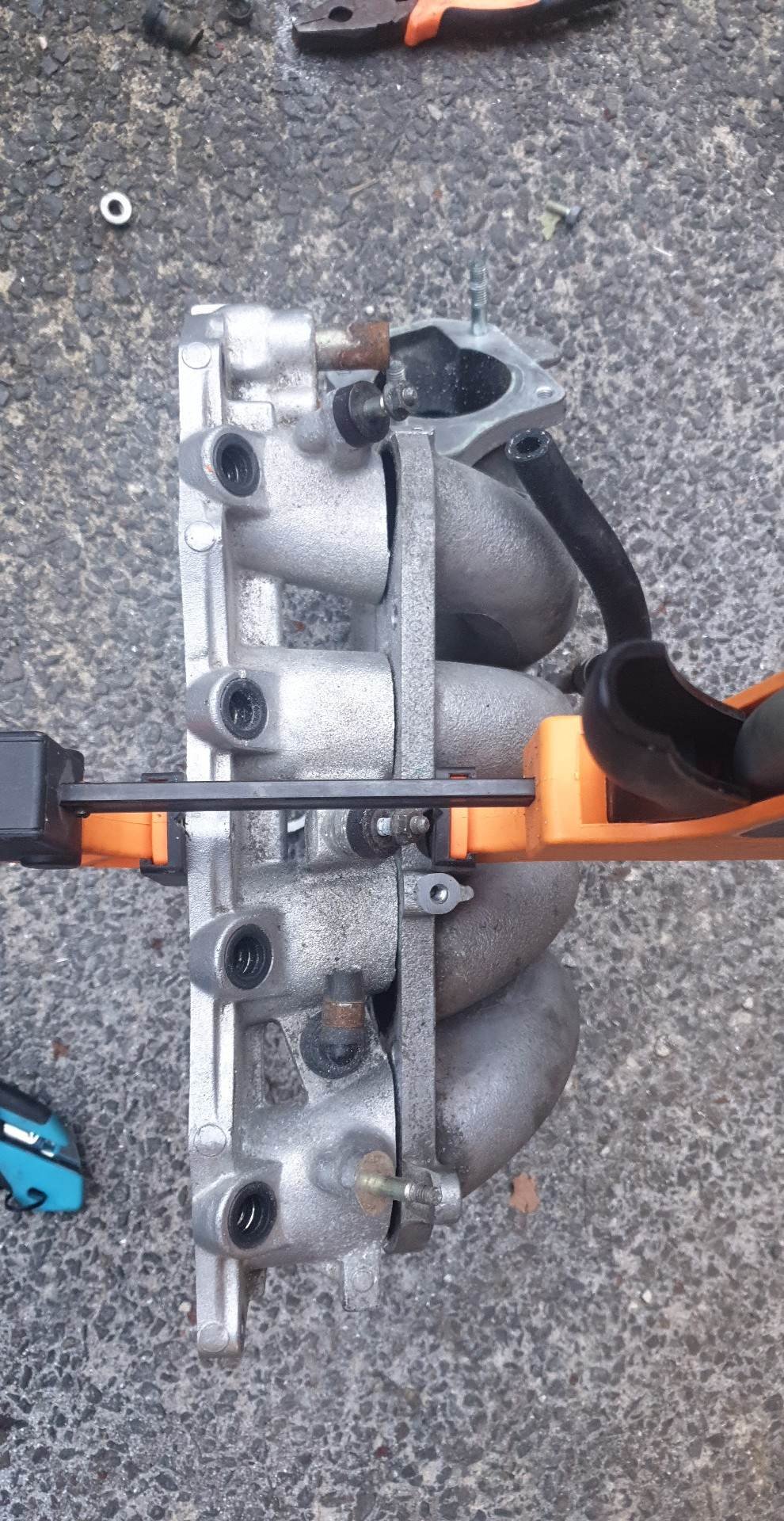
Itb manifold part deuce: New runners are 95mm long 2" OD aluminium tube with 3mm wall thickness. I'm using 10mm thick aluminium plate as the flange, which will be trimmed to size later. I made a real effort to get the angle just right to match the port angle. Looking down the trumpet at WOT you will be able to see the top of the piston! I can't shorten the runners as them parts of the fuel rail interfere with the throttles. The comparison between the old manifold and new one is quite stark. Also, I'm not so sure if the new one will clear the bonnet... But the main issue is the TPS now will interfere with the clutch res. Anyway, I haven't welded everything together as I have quite a bit of prep and tube "massaging" to make everything fit. Still I'm happy with this progress.
- 70 replies
-
- 14
-
-
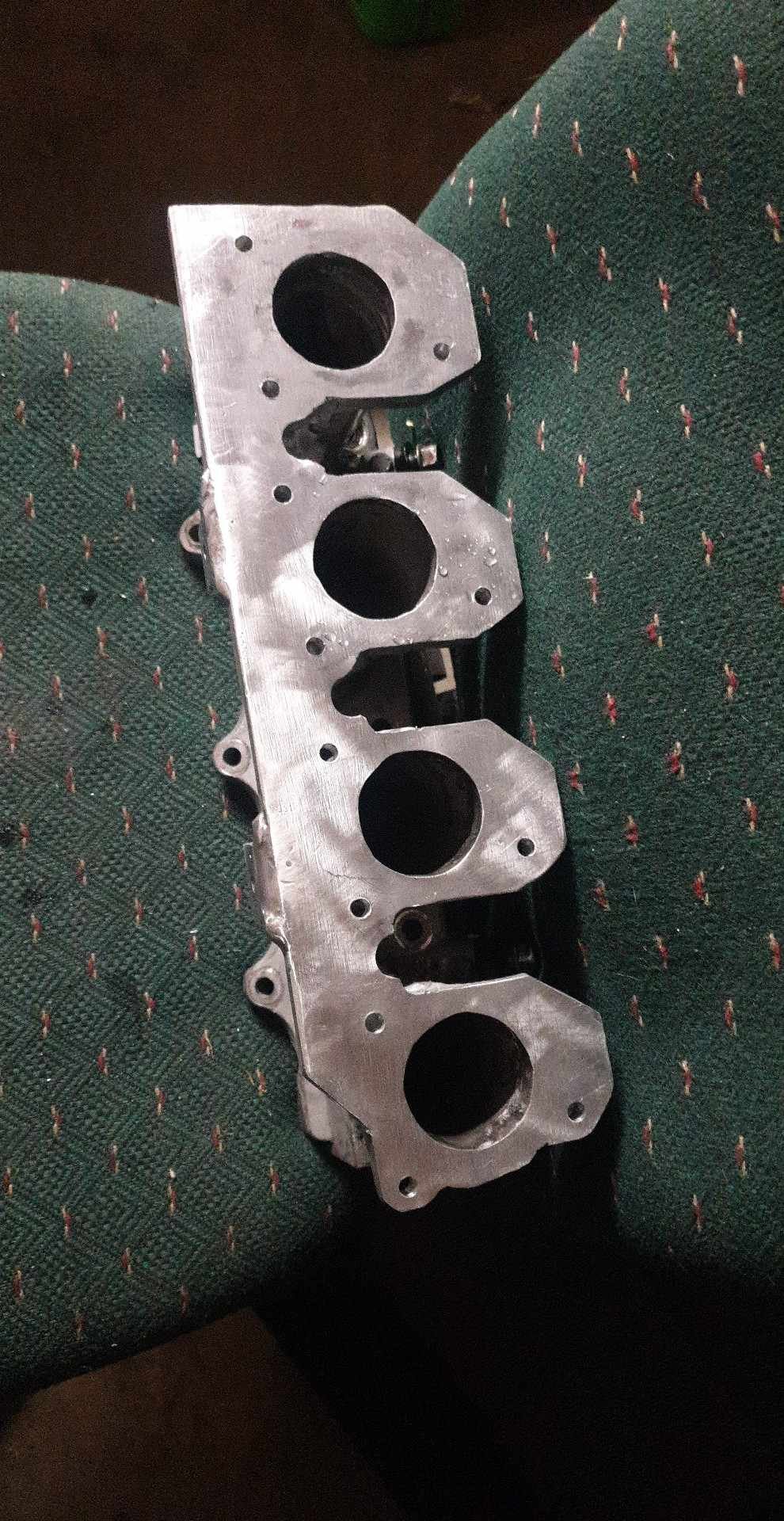
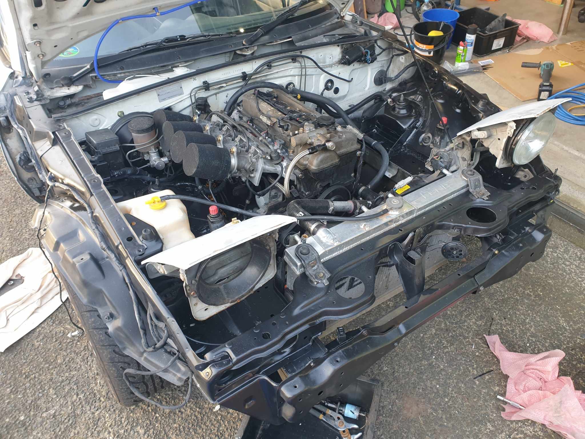
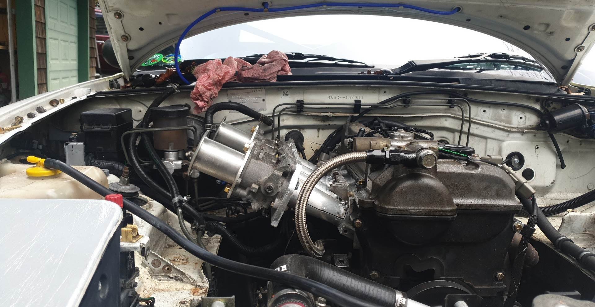
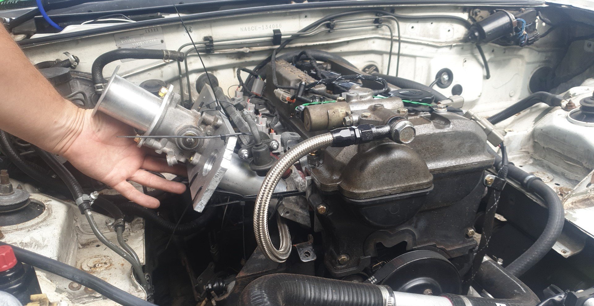
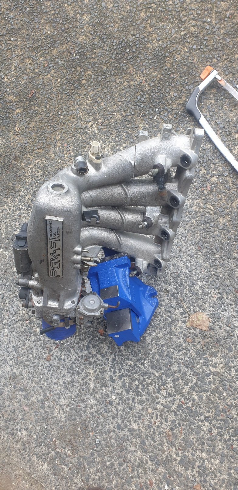
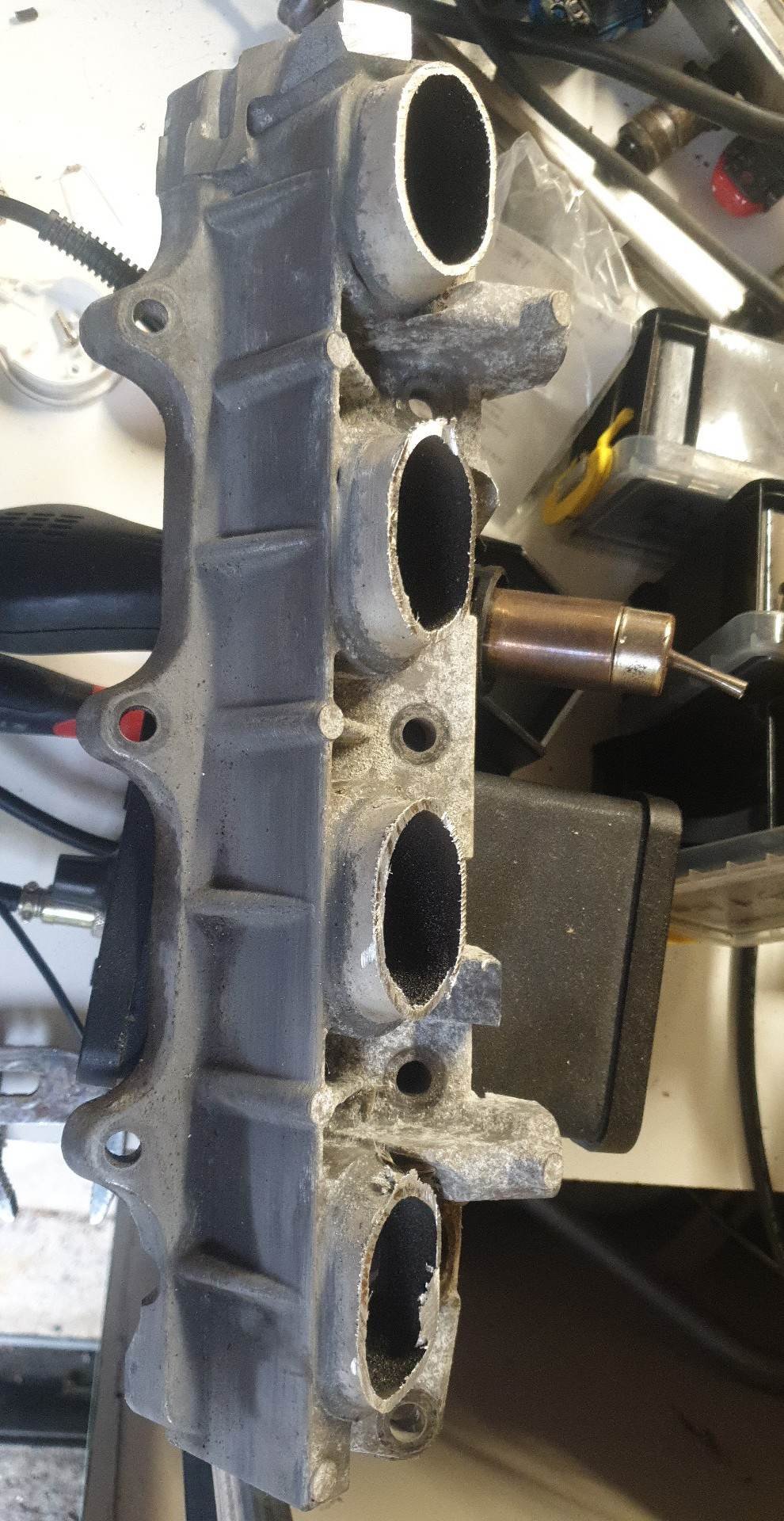
This might not be worthy of the second post here but we knew it was going to be slow, so it'll just be a small update. Anyone who's seen my Mazda knows that chopping intake manifolds seems to be my favorite pastime but I PROMISE that is not the case! Today I purchased a K24 RAA intake manifold, which has a very nice 2-piece design. I also cut my ZC intake manifold in half, shortening the runners but attempting to line them up with the RAA's plenum section. I intend on cutting a flange and welding it to what's left of the ZC manifold allowing me to bolt that to the RAA manifold. Space-wise, this has saved me maybe 10cm at the back of the engine bay which is a huge amount. In the bottom picture you can see just how much space saving this really is. The picture is only the start as I have already trimmed a further 4cm from the Honda intake manifold (up to the fuel rail mounts), saving additional space again!
- 3 replies
-
- 10
-
-
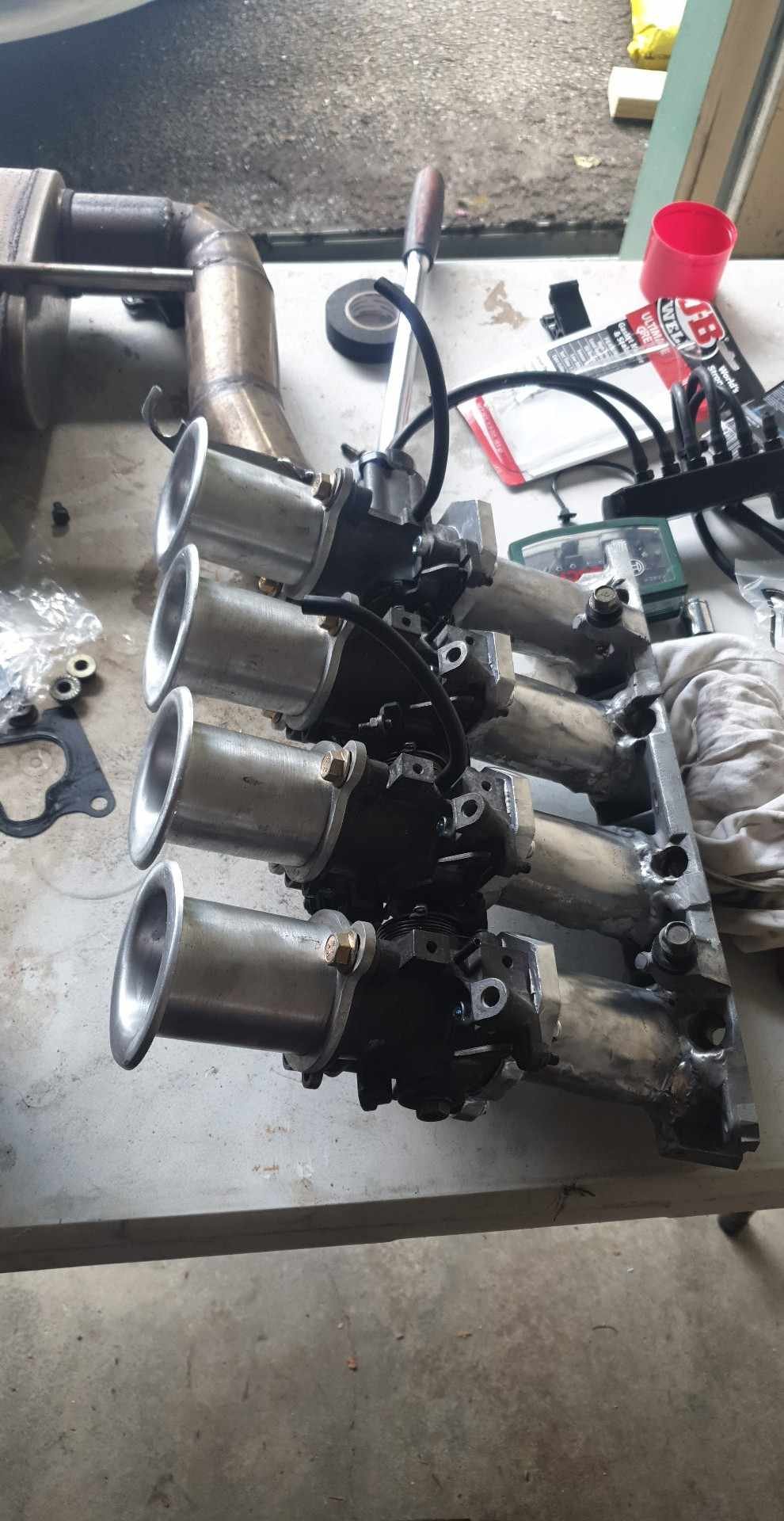
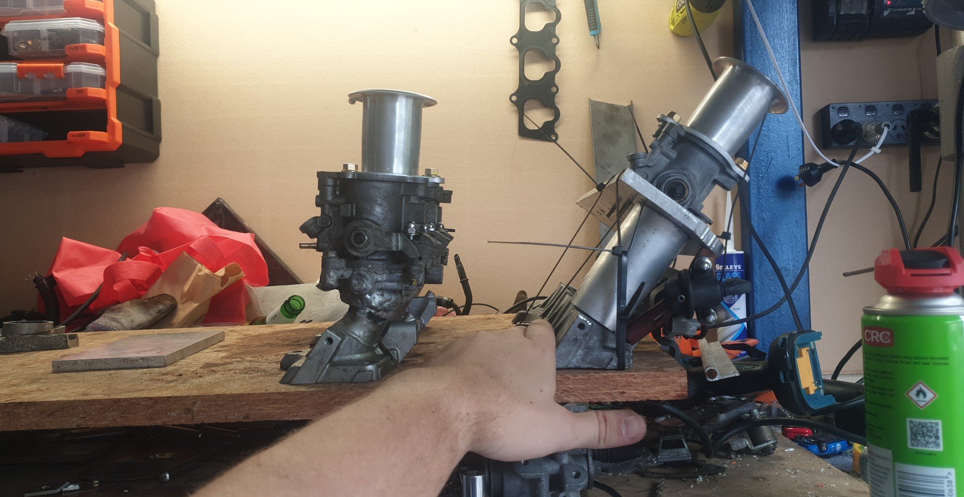
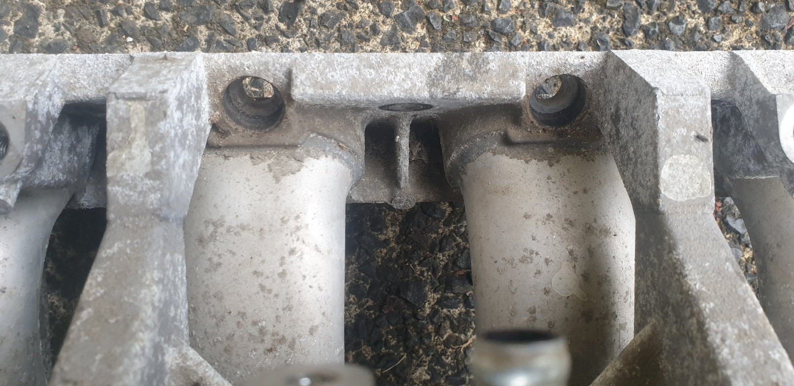
So I don't have a 3d printer but I diiid borrow an AC Tig welder, so I'm "here we go again"'ing it and going to make my replacement intake out of aluminium, just without the gross bend. Here you can see how even the stock runners "flared" where they were joined to the old intake. The cross sectional area increases quite significantly here, which is bad mmkay. Next, a little illustration of where my old manifold was cut and shut. Now here's me using a totally normal and not at all weird method to hacksaw through this manifold. I hate hacksaws but my angle grinder was hating this more. And lastly, the chopped manifold. I intend on cleaning those holes up with the angle grinder flush to the flange, and then using the die grinder to cut out the rest of the tube from inside that hole. I think from factory it is basically glued in? Im going to make a flange for the 4age ITBs to come straight off this flange at the same angle as the ports, just barely clearing (or even mildly touching) the fuel rail. Anywho, hopefully the aluminium tube and plate will arrive this week so I can weld up the runners properly!


.jpg.1101d0c52d81bfbbb832e5c82c471c76.jpg)
.jpg.4beae19c1504bd06a68a78a7c3a6ea1a.jpg)