

Hurmeez
-
Posts
341 -
Joined
-
Last visited
-
Days Won
1
Content Type
Forums
Downloads
Events
Gallery
Posts posted by Hurmeez
-
-
I don't have a pedal or remote amp controller on the machine. Do you guys have any experience with trying to use a machine like that or am I making it all far more difficult than it has to be?
-
I'm really struggling to find the sweet spot between too hot and too cold. I'll either take ages to make a tack, or it'll just melt and piss off on me. I realise that as I keep welding it gets pre-heated and I shouldn't need as much heat in it to continue but it's just so much different to steel it's like learning to ride a bike again but the pedals turn sideways and the handlebars make the wheel turn the opposite. I've given up for tonight before I turn all my donuts into a puddle on the floor.
-
Thanks for the tip. I've just been tacking so far but it's not too bad. The biggest difference I find is how it doesn't "jump" the way steel does when you've got two puddles next to each other. You've really got to force them together with the filler which can be a pain when you run out of hands to hold things together.
-
 1
1
-
-
- Popular Post
- Popular Post
So my donuts finally turned up a couple of days late. I didn't think to take a pre-cutting photo but this was what it looked like when it turned up:

I got stuck straight into cutting them up and hoping like hell I didn't screw them up. I made up a quick and nasty jig to help make sure each cut was made square to the center line and therefore the round profile was retained.
It could have been better but it more or less did the job.
With the jig, I got each bend cut out quick smart and taped it all up. Here is the passenger side:
And the driver's side finished up too:
Of course, I had to sling it into the bay and check out the fit. It'd be rude not to really.
I learned a couple of things. Firstly, there isn't an awful lot of room between the passenger side strut tower and the intakes.
Secondly, there isn't a lot of clearance between the TPS and the upper bulkhead at all, and no room for the clutch fluid reservoir in the position I had it.
I can solve that piece of cake though by scalloping the bulkhead slightly and repositioning the clutch fluid reservoir somewhere more convenient, a handy side effect of having a remote reservoir.
I also threw the bonnet on and checked that for clearance. Here is the view through the heater bubble hole:
Looks good...
And from the front:
Heaps of room.
Tomorrow I'll see about making some tweaks to try and blend the original manifold flanges into the bends better, as well as hopefully make a little more room between the strut tower and the intake. Then I'll see what kind of a mess I can make of the whole lot with the welder while making dort noises in my head. Should be swell!
-
18
-
That's an interesting exhaust manifold setup they've got going on. The filters are cool too. I'm not sure what I'm going to do at that end yet.
-
1
-
-
- Popular Post
- Popular Post
As some of you may know from the discussion thread, I took the plunge and bought a set of ITBs. It was always my plan to put ITBs on it eventually but I was originally going to just throw a single throttle body type manifold to get it running. Instead, I figured bugger it and pulled the trigger on them now.
They're off a BMW S85 V10. 50mm throats with a super easy to modify link shaft that runs through the whole lot. Massive thanks to @d.p.n.s for helping me sort them out. The bonus of buying 10 means I have some to throw at my old man's zetec which is planned to go in his Mk1 Escort somewhere later down the track.
After waiting a week for them to arrive I was bitterly disappointed to find that they may not be as easy to fit as I initially thought. After much head scratching (and bashing) and help from the brilliance of the hivemind ( @yoeddynz, @d.p.n.s, @Transom), I came up with a good solution to fit them under the bonnet and let air into the motor as intended.
I have two 2 inch alloy donuts arriving tomorrow which I can section up to make the intake tubes. They'll be something like the cardboard shapes mocked up there.
It should give me at least 15mm bonnet clearance at the closest point and if the engine mounts do flex enough to take that up then I can massage the runner until it's no longer an issue.
I drew up the flange in cad and stuck it to a mock-up piece of MDF.
I tweaked the shape a little then printed it again to make the final flanges from aluminium
The ITBs have locating lugs on the bottom of the bolt holes so the tapped holes are counterbored to make for a snug fit and positive location.
Next, I drilled the biggest holes I could,
Then chewed out the final shape to a high degree of accuracy, considering the tools at hand.
Laser cutting would have been way quicker and easier, but this was much cheaper financially so I'm more than happy with the result.
Hopefully with the arrival of my donuts tomorrow, I can start sorting out some intake runners and figuring out this ally welding business. I can't wait!
-
11
-
Also, check this out:
I'm basically building a Porche. Please send all fan mail to hecticklswaps@yourejealous.com.
-
1
-
-
I'll be honest. At this point, I had a bit of a crisis about what to do next. I felt like I'd done everything and I was struggling to figure out what else I had to do. That was until I remembered all the panel work I'd put off to instead make the engine fit. So that was the next logical step. Back to rust repairs. Oh goodie!
Of course, since that was the next logical step, I went and did something else instead. You may remember me mentioning a while back how I was planning on modifying the radiator side supports to fit the massive new rad. Well, I made that my next mission. I started with a cardboard template of the panels I had already made all those months ago and placed them more or less in position.
Then I cut it down to clear the rad.
Then trimmed the premade panels to match, complete with a folded flange on both outside and inside edges.
They're just sitting in place for the photos so they actually fit much better than they appear to.
With that done, there really was nothing left to do other than start on some rust repairs.
I noticed some bubbling around the bottom edge of the driver's door a long while ago but put off doing anything about it until now. I started by stripping the paint back over the bubbled area and quickly realised how much bog was all over the door. So I carried on and stripped the whole door, exposing a multitude of sins.
First, the original issue was revealed to be an old rust hole that had been "fixed" by filling it with bog and calling it done.
Then there's this hectic az mirror delete too:
Just half ass weld a patch through the holes and punch the whole lot in with a hammer. Then it's easy as to bog up and no one will ever know! Easy two-step guide for any beginners out there.
Probably at least 10mm over most of it. Nothing wrong with that.
I initially thought that this skin was beyond my abilities to save (or my being bothered to save it) so I looked at a brand new skin. After seeing how much they want for one of them I quickly decided that perhaps I could fix this one after all. I decided to start with the rust hole on the bottom edge.
Before I welded it in I sorted out the frame underneath it where the same rust repair technique had been used.
Then it was the skin.
I did it really slowly and ended up with fairly minimal warping
Then witness paint makes it look far worse than it actually is. Because of the inner door structure, it's really difficult to get a dolly in behind it to do any meaningful panel beating but as it is I'll get away with a maximum of 1mm of filler to smooth the whole thing off. I'm much happier with it now, if only for the fact that there's some real steel behind the paint.
I still have to sort that issue on the left hand side, as well as the meat hook abortion situation around the mirror. I'll get back to it in a little bit but I found something way cooler to work on right now. Stay tuned...
-
5
-
-
I agree, the silver top bodies would be a good fit. Unfortunately, I already went and bought some bimmer ones so I'll go ahead and make them work for now. It's funny you mention the cam covers. I think I can get away without modifying the passenger's side cover, however, I was originally thinking of relocating that breather vent on the driver's side because it looked like it would be in the way of the front-most body. Then I realised I'd be better to take the mountain to Muhummad so to speak and just shift all the driver's side bodies a little bit rearward to clear it. I already drew up the mounting flanges ready to be laser cut and I think it'll all turn out pretty good.
If you do manage to figure out a way to make the driver's side cover look more like the passenger's with the badge and whatnot, I'd be pretty keen to buy one off you. It bugs me too not having them match.
-
1
-
-
I did consider lobsterbacking but I don't think I have the ally welding skills to attempt that sort of thing just yet. Also, it would end up being so much welding just for one, once you multiply it by all six runners I think I'd end up suicidal by the end of it. Not to mention the cost of the gas. I looked into ally donuts and I can get really tight radius bends for close to the same price I'd probably end up spending on gas just to do all the lobsterbacking, so I think that's the go on that route.
-
1
-
-
You know you're the second person to suggest the NOS idea. I think I'll go for a non-permanent bung in the BMW injector port for that very reason. As for the IACV, the one @Avenga used on his wagon looks like a really neat solution (if a little pricey). I think I'll have a look for a cheaper wrecker jobbie first but if all else fails then that's a good option.
-
Bonnet holes and humps aren't really part of the look I'm going for, unfortunately. As much as the idea of winding 30psi into a stock block with no issues sounds appealing, the iron block is less so for me. Also, them revs!
That said, check this out!
It's going to be close but I think I can actually get away with it. I'll use the Mazda injectors and bung the throttle body injector port. I may have to flatten the very top of the front driver's side runner to stop it knocking when the mounts flex but other than that it should work.
-
1 hour ago, d.p.n.s said:
hay man regarding the ITBs ..cant make them fit this way?
I think I checked it that way but I just don't think I have the bonnet clearance. I suppose I could have a go with some flattened runners but to be honest I was a bit gutted and pushed it into the corner and felt sorry for myself for a bit. I must get back out there and have another look.
-
1
-
-
Everything you do is one less thing to do later on. That's what keeps me going mate
-
1
-
-
What a sweet gig!
-
6 minutes ago, d.p.n.s said:
Probably does....
Love it
-
Also what do you mean by "joints" being supplied? Surely that's not what I think it means?
-
That's interesting. The interwebs reckon the RX-8 box is 46 kg dry so that gives us a nominal weight of ~185 kg give or take. Compared to 31kg for the Type 9 gearbox, plus 135kg for a "fully dressed" pinto, gives a total of ~170kg. So ultimately they appear to be very similar. Theoretically anyway. Makes for an interesting thought experiment.
-
I just pulled the motor and box out for the next stage of work and yeah it was pretty heavy but I could still lift one end at a time unassisted. I'm really curious to know the weight difference. Maybe one of these days I'll sling the pinto and type 9 up on the hoist with a scale and compare the two. I'd say the iron block on the pinto should make it a fairly even match.
-
@yoeddynzI'd be embarrassed to tell you how many times I've watched the video of your first startup Alex just to keep myself on track. That and videos of MX3s with ITBs dorting in some kid's driveway. I can tell you I am so looking forward to hearing it zing up that high. I might take you up on that offer of your maps too. I was originally going to go ITBs, even got so far as importing a set of BMW ones from Germany, but it turns out with the space that I have and my now somewhat reduced budget due to the said unusable ITBs, your style of manifold is my only real option.
@d.p.n.s It's a sickness for sure!
-
1
-
-
Preaching to the choir there mate. I often think about how many kms I could have already done if I'd just stuck with the Pinto and thrown a lumpy cam in it. May have even driven the car to school before I left. Instead, here I am still bashing my head against an alloy v6 that barely fits. But hey, if I wanted it to be easy I could have bought a finished one in the first place, and where's the fun in that?
-
2
-
-
Ah, gotcha I was thinking of something different then. I was thinking this:
And you were meaning this right?
The CalTracs are basically the same as what you've got but with a bell crank that pushes down on the part of the spring that is bending up during the wrap, rather than a free-swinging arm slapping away.
The crank pivots around the front spring mount and gives you the advantages of both looking cooler (in my opinion), and eliminating the noise and fatigue of having the bar hitting the underside of the spring.
I might use a spare set of spring hangers to begin with, and make a temporary setup like you said to see if I'm willing to put up with it, before possibly going to a full-on CalTrac style setup later on.
-
2
-
-
Really? Is that all it takes? I've read that tramp bars only really increase the frequency of the tramping rather than getting rid of it properly but I suppose you'd know far more about it than me. I have been looking into a CalTrac style of thing though. They look like a good bolt-on solution without many drawbacks other than the fact that I'd have to build my own version because they don't make one for an Escort. I feel like if I was going to go to the effort of putting in anti tramp bars then I might as well go the whole hog and four link it with fairly short top arms.
-
From what I've read it's a perfectly workable suspension design for the street or light driving but where it tends to fall down is hard launches and burnouts etc. Because of the way the axle wants to twist under acceleration it will be lifted up into the belly of the car and away from the road surface. This means you'll lose traction and potentially still have axle tramp/wheel hop when you drop the clutch, both things I was trying to get rid of by thinking about a link system in the first place.
So all in all, it works, it's just not worth the effort for what I'd get in my application in my opinion.


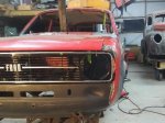
Hurmeez' 1977 Mk2 Escort Estate
in Project Discussion
Posted
See the thing I'm tossing up right now is that for the price of that helmet, or a foot pedal for the welder, I can get a mate to weld it up for me professionally. He's been doing it for a living for god knows how many years and is bloody good at what he does. It being such a central visual piece of the engine bay obviously makes me want it to look good but with my current equipment, I don't think I can make that happen. It kills me to not to do it myself but this will be pretty much the only ally welding I'll need to do on the car and I don't think I can justify the investment at the moment, especially since pretty much all work on the car is going to have to stop next year while I'm studying down south with nowhere nearby to store or work on the car. Somewhere down the track I'll definitely get more into it and upskill but for now, I think as much as it sucks, I'm gonna take the easy (and cheaper) way out and get someone else to do these particular welds.
Thank you guys for all your tips and I think I'll keep trying and practicing and teaching myself on scrap but I think it's a big ole no bueno on the actual intake.