Hurmeez
-
Posts
341 -
Joined
-
Last visited
-
Days Won
1
Everything posted by Hurmeez
-
Well it's been the better part of eight months since the last installment. There's obviously not been nearly as rapid progress, however, I feel that enough has happened to finally make it worthy of a post. To begin, I finally moved into a new place in Auckland with access to a closed in double garage. I do have to share it with a flatmate's car but I'm very glad to finally have the car back. However, ever since I've been working pretty much constantly so haven't had a lot of time to work on it. That said, I found a nice sturdy bench on marketplace, got given a vice from the old man, and started to get myself established. I'd been holding off on buying a grinder and panel beating tools until I could find a really good deal. In the meantime, I started drawing stuff and making plans. The first being what to do for my air filter. I went through lots of designs in my head before finally getting this down on paper. The original design took all the right mathematical ratios into consideration from this document: http://www.nsxprime.com/w/images/9/9e/(Blair_and_Cahoon)_Design_of_an_intake_bellmouth_Sept._2006.pdf It had the right trumpet length and radius and all the bells and whistles. It's designed to slip over the end of the throttle bodies with a snug fit and a pair of grub screws top and bottom to secure it. It was a pretty good looking design in my opinion. But as the saying goes, no plan ever survives fist contact with the enemy. When I went to check the available space on the car, I realised I had about half the height space I would have needed, hence the reduced trumpet height and the filter being sunk down over the top of the bell mouths themselves. It's designed to use a K&N E-3515 filter which is basically the biggest one I could fit. At this point I planned to make it from aluminium and teach myself to weld it up properly. Since I don't have an AC TIG, I was going to make a weekend trip back up to Whangarei and use my dad's lathe to make the trumpets and his welder to stick everything together. That was until people started getting sick. My partner and I booked time off months in advance to go on a fake Easter weekend with her family back up north. It's been a bit of a tradition for the last few years and lets us get away without having to deal with huge crowds of people on real Easter. That was booked for the 20th through to the 23rd of March. The weather wasn't great so we came back to Whangarei from camping on the Sunday to reports of the COVID situation getting worse. I figured it would be a bit shit to be stuck inside for a month with no tools to work on the car so I finally bit the bullet and bought a grinder, drill, regulator, TIG rods and tungstens, and borrowed some panel hammers and dollys from dad again. No sooner had I got back from shopping to where we were staying in Whangarei, the news of the lock down was announced and my partner decided that there was no way we were going to head back down to Auckland to be by ourselves, when she could be with her family up here the whole time. So here I am with all the gear and no car. Stellar. Eventually, I got bored enough to start thinking again. I started making a cardboard mock up of the intake to check its feasibility, especially how difficult it would be to make from flat sheet materials. To start, I did the maths and divided up the trumpet shapes into 16 segments which I could cut out of cardboard. This was a good proof of concept. I was gearing up to make the other two when my father in law suggested that I could make the whole setup from carbon fibre. He makes his own telescopes at home, including a seven odd foot tall one with something like a 14" mirror, all handmade. He has done a bit with carbon fibre and suggested I use his lathe to make a mould and lay the whole lot up instead of struggling with a welder. Well, hanging off a lathe for a day or two was a lot more appealing to me than playing arts and crafts so I swiftly pivoted and started to make it happen. Starting by printing out the profile of the trumpet and transferring it to some scrap flat bar, I made a profile tool for the lathe. It's only mild steel but it's still harder than the MDF I plan to use. Then I stacked up said MDF and screwed four layers together to get the height I'd need. Finally, I threw it in the chuck and began pecking away at it. It didn't leave the nicest finish but I wasn't too worried because I was about to encase everything in resin. The wood makes for a good scaffold but the resin should give me the smooth finish I'll need for a good release. I mixed up the epoxy and poured it on, only to realise that although I was assured the mix ratio was 4:1, it does pay to confirm for one's self. This is what happens when it's actually supposed to be a 5:1 ratio. It was off gassing like a mother and started to rise like one of those baking soda and vinegar volcanoes you make as a kid. When I did peel the tape off, it was so full of bubbles and voids, there was nothing for it but to take it all off and start again. Skipping a few steps because I'm out of practice with taking photos of everything I do, this is the result of re-machining the resin. There is also a few layers of primer on top, as well as a couple layers of clear coat. Now would be when I would put some mould release compound on there and start the lay up process. I say would because I don't have any carbon fibre yet so I'll have so I'll have to wait until the restrictions ease. I plan to attempt to make the mould for the other parts of the design as well so I'll update that as it happens. In the meantime, I'd appreciate any feedback on the design and process on the discussion thread in my signature. Cheers.
-
Yeah I'm thinking the tank will make it fairly simple. Current plan is to decide on a late model in tank pump and emulate the baffles/shape of the tank it comes out of. Still a bit down the track though.
-
Lookin great so far mate. Don't know if I might have missed it in a previous post but I'm wondering about baffling in your tank. Does the tank come with some already or do you reckon the pump hanger will be enough to prevent any starvation issues? Just starting to think about ways to do my tank.
-
It did come from Kerikeri so probably a midnight auto's special
-
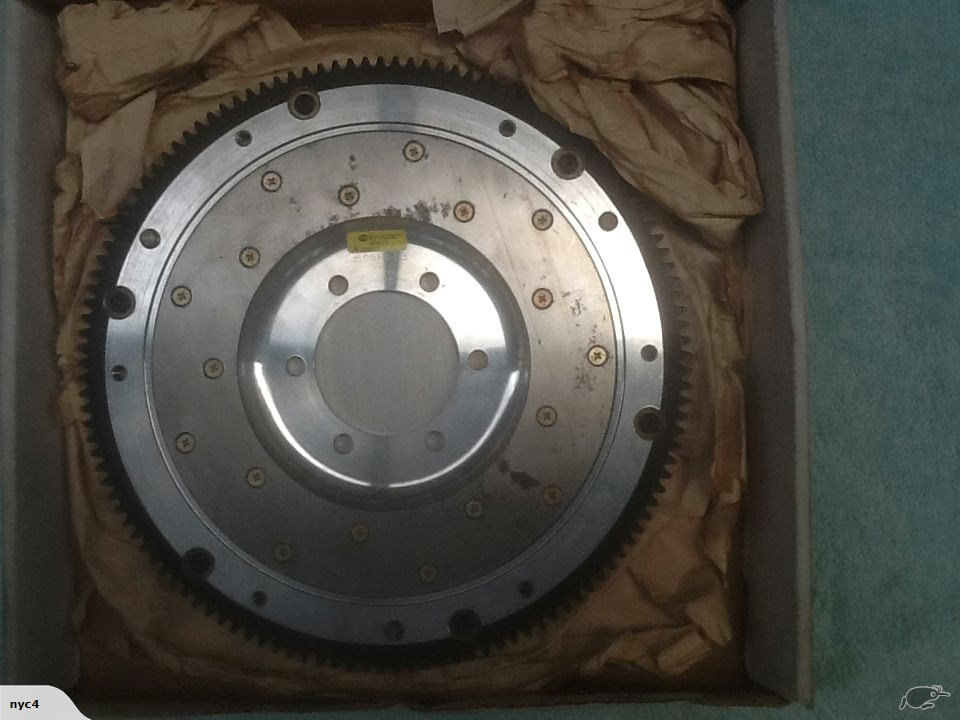
I think it is a Fidanza, either that or a well-made copy. It had the Fidanza part number on the box and looks like all the pictures online so I'm fairly convinced. It also has an SFI certification sticker on it and they're of course impossible to fake. The only reason I think it might be a copy is it only cost me $250, admittedly second hand but it is in essentially brand new condition as far as I can tell. I'm absolutely frothing to get back at it properly, already looking at places with garages to rent while we've still got four months left on our current contract. Can not wait.
-
I've been very interested in how you plan to do your filter setup. Looks great so far and I'm keen to see how it turns out!
-
So now here we are six months later and I've come to my second of two one week holidays for the year. This whole time I've still been mentally working on the car, thinking through all sorts of different problems and making plans and drawings along the way. Now I've had some time off from school, I made a trip back up home and put one of these plans into practice. However, before I can get into that, we have to go through a little story time first... It's long been playing on my mind the fact that I'd still not fully completed the V6 RWD conversion. Sure I'd made the adapter plate, engine and box mounts, intake setup, and sump etc, but the actual connection between engine and gearbox was still missing. The flywheel and clutch situation has been through a few revisions, both in my head and in physical work. You may remember from these posts: that I planned to use the standard V6 flywheel with an extra ring added to increase the outer diameter to take an RX8 ring gear as well as a spacer to bring it out the correct distance to take run the RX8 clutch and pressure plate. After making the spacer (which if I'm honest now I wasn't particularly happy with my workmanship and tolerances anyway) I found that the RX8 friction disk wouldn't work with the V6 flywheel or pressure plate, meaning I would have to adapt the RX8 pressure plate to the flywheel. So upon taking it to the machinist to get his opinion on making the adaptations for the larger ring gear and pressure plate, we found that pressure plate bolt holes would end up directly on the junction between flywheel and adapter ring. This was doable but it was far from ideal. Also, the labour involved would have cost similar amounts to a fully custom flywheel anyway and thus the whole plan was put on hold for a while. You may indeed have noticed this in the complete lack of a mention of the clutch and flywheel in the following posts. And so came about my next plan. Ever since reading @yoeddynz's viva thread, I'd been pretty keen on using a lightened flywheel to help unleash the engine's propensity for revs. Luckily, this was going to let me kill two birds with one stone. I'd decided long ago that I wanted to keep everything inside the bellhousing exchangeable with standard RX8 parts. This will allow me plenty of potential clutch upgrade options in the future. With that in mind, I went looking for RX8 lightened flywheels. Almost exclusively, lightened rotary flywheels are designed to bolt up to the automatic counterweight, rather than using the integral counterweight cast into the standard flywheels. This made my life much easier. Now I could make an adapter that picks up the six holes in the flywheel, spaces it the correct distance to use the standard RX8 clutch and pressure plate, and bolts to the end of the crank like the normal V6 flywheel. Essentially I can make a counterweight emulator. The next step was to decide the material to make my adapter out of. I could of course just use any old steel billet lying around the shop but my fondness for my feet kind of convinced me not to go that route. So I looked at what material is usually used for steel lightweight flywheels and found that 1045 is common. I figure if it's strong enough to take the forces on a whole flywheel, then it should be well strong enough for my much smaller diameter adapter. Next, I had to take measurements of everything and design the actual adapter itself. And this is what I came up with. You'll have to thank the American's for building the majority of commercial aircraft in service for my use of imperial measurements. Almost all the tools used in the industry are in imperial and because of that, all the tools I had available at school are as well. Anyway, according to these dimensions, the ring gear should end up in the same position as the RX8 relative to the bell housing face and starter, and therefore the rest of the clutch system should work as normal as well. With all this done, I could finally go home and get stuck into it. Step one, of course, was to get the raw material into a useable state by facing it up and generally roughing it out. Thank god for power feeds and tungsten carbide tools. Next, I turned the recess that fits over the end of the crank concentric to the outer diameter of the material. With that done, I turned the piece end for end and dialed everything back up in the four jaw to turn the spigot that that flywheel runs on. This is also concentric to the outer diameter and, by extension, the recess as well. This is obviously crucial to avoid vibrations and undue wear on bearings and so forth. You'll also notice the stepped section on the front of the spigot. This is designed to fit the inside of the standard flywheel for reasons that will become clear later on. With those surfaces all machined, the crucial dimensions are done and I can have a nice big exhale. This means I can move on to less nail-biting procedures. One thing I did learn from the first spacer I made way back in the day is that measuring and drilling PCDs is a right royal pain and very difficult to do accurately with the tools I have available. So this time around I decided to forgo any and all measuring of PCDs entirely and use a far more analog method. I already have the PCD that I'm trying to match. Why would I not use it to guide my drill bit? So with that in mind, I made up some bushes to guide the pilot and tapping drill and protect the aluminium flywheel. Next, I clamped the flywheel and adapter together and shifted everything to the drill press. You can see the bush already in place in this photo. Once I had the first hole drilled to size, I tapped it to M10 x 1.25, which is the thread used by Mazda on the automatic counterweight that this flywheel is designed to bolt to. With the first hole tapped, I bolted the flywheel to the adapter, which let me get rid of the whole clamp setup and drill the subsequent holes much more simply. I used a similar setup for drilling the crank bolts too. I wasn't nearly as worried about damaging this flywheel since I won't be using it once it's done its jig job, so I only used a bush for the pilot drill and just threw the final drill through using the flywheel itself as the bush. Now that all the holes were drilled I decided I ought to check my tapped threads for strength now, rather than do all the rest of the work just to find that they strip as soon as I try to put any torque on them and junk the workpiece. So I throw the first bolt in and torque it to the high limit of the 32 - 45 ftlbs recommended by Mazda for the flexplate bolts. It goes tight, tight, tight, still tight, still turning, still turning, shit. I figure its stripped and fucked. So out it comes and sure enough, the bolt thread is gone burgers. However, the female threads are still pristine. Stoked. So in goes round two. Tight, tight, tight, still tight, still turning, still turning, shit. Again. So, out she comes and another bolt failure. This time it stretched the crap out of the bolt but still left the threads perfect. Third time was the charm though and all the threads eventually took the torque like champs. Guess that teaches me for using the first bolts I find lying around. Finally, I put everything back into the four jaw and faced something like 15mm off the spigot to bring it back to flush with the flywheel face and finalise the outside dimensions. Here you can see me checking the runout of the flywheel when mounted and it was well well within the 0.008" tolerance specified by the Mazda service manual. Finally I bored the recess for the spigot bearing. I decided to use the MX6 spigot bearing, mainly because I had one available, but also because it fits the RX8 input shaft perfectly, and it was much easier to machine the larger bore for than the much smaller stock roller bearing used on the RX8. It's a very light press fit, able to be tapped home with a mallet just like the fit in the original V6 flywheel it came out of. Finally, after two straight 14 hour days on this thing, I was ready for a dry fit. I used the longer crank bolts that I bought for the first spacer which gave me shed loads of thread engagement, as well as a couple of M10 bolts I had lying around for the flywheel itself. I'll get some proper high tensile ones later on. Next was the clutch and pressure plate which I eyeballed the alignment of and used some more M8 bolts I had lying around. Finally, I muscled the gearbox around and offered it up. With the engine and box somewhat leveled the input shaft slid right in and home over the adapter plate dowels. A couple of bolts later and I stood back to admire my handiwork. It is a beautiful thing indeed. I couldn't help myself at this point and threw a driveshaft in the back end and a ratchet on the front and low and behold we have drive!! I have to apologise for the photo quality at this point. I think there's a smudge on the inside of my lense somehow and it wasn't having a great time with the fluorescent lights at 1:30 in the morning. I ran it through all the gears and checked the disengagement with the BFC in the bottom of the frame, and it does indeed stop spinning the driveshaft with the clutch in while still having a small amount of wiggle to the arm when out. I also checked the starter engagement with some white paint pen and it looks to be exactly where the existing wear marks are on the starter gear. I'd have loved to hook up a battery and some jumper leads to spin it over with the starter but I did end up running out of time. With all said and done I am absolutely stoked with how everything worked out. My measurements and calculations were apparently right on the money, and my machining workmanship and tolerances are leaps and bounds ahead of the spacer I made initially. The final setup for my adapter situation comes out to this: Custom 12mm steel engine to gearbox adapter plate of my own design Custom 1045 steel flywheel adapter of my own design Aftermarket RX8/Turbo RX7 lightweight aluminium flywheel 6 speed RX8/Turbo RX7 clutch and flywheel MX6 spigot bearing Stock RX8 clutch arm/release bearing If you've made it this far though what was a whole afternoon of typing then thank you very much for reading. I'd appreciate any comments or feedback on my discussion thread which you can find here: That's it for now. Hopefully won't be another six months before the next update but we'll have to see what happens. Cheers.

-
Cheers guys, I'll give them a shot.
-
I'm looking for somewhere to buy a round bar steel offcut or similar that is about 35mm long and 135mm diameter. I realise it's a pretty out there sized chunk but I thought I'd give your guys' knowledge a shot before I start ringing around tomorrow afternoon.
-
I really like what you've done with the trumpets on the itbs. How are you sealing/fixing them to the inlet of the throttle body? I've been thinking about welding a modified off the shelf trumpets to some heavy wall ally tube with a shoulder machined into it and running with an o-ring to make them snap into place but I'm curious to hear about how you went about it.
-
Preaching to the choir here mate. It's transitioning back to the rust that's the killer.
-
Those dimpled holes look stellar man! You've done a fantastic job on that whole area.
-
Who's coming this month? I'm keen to catch up again after my first meet last month!
-
No worries, only too glad to get my fix helping others while I'm stuck with my withdrawals.
-
That's a good point. Personally I'd use your current setup as a jig (so to speak) to make two new standalone mounts and a new cross member. That way you don't need to put the motor and box back in and you can do away with the extra mounts at the same time.
-
I'd say while you have it at this stage with it on the spit it should be easy enough to drill the original mount spot welds out and shift them back a bit to better match up with the box. Then you can make a straight across cross member and make everything nice and strong.
-
I might have to grab a burger after school then and see what's shakin...
-
Thanks very much mate, I appreciate your support. Just for future reference, we don't post on each other's build threads here to help keep down the clutter and make each thread easier to follow. By all means, head over to my discussion thread and have a yarn though. There's a link in my signature.
-
As in body fill lead? Does it help take some of the harshness out of it?
-
Which brings me to something of a bittersweet post. With the handbrake all sorted, I shifted my attention to sorting out some last few half-finished things. For example, I made final confirmation of my driveshaft angles at ride height and fully welded the rear spring pads to the diff. The welder sure does sing at full noise like that but it was super satisfying to get it sorted. With that back in and bolted up, I put the front end and doors back on. The guards and doors are bolted on as normal but the front panel, slam panel, rad supports, etc are all tek screwed on. Also, the bonnet went back on, radiator in, and the latch mechanism made to work. Moving inside, I threw my dash topper pad and heater box in, As well as front and rear seats. Next, I pulled the front wheels and bolted up my princess calipers. They're just the bare housing at the moment because I haven't got round to putting my rebuild kit to use. Finally, I pulled all my spare parts out of storage and stacked them in the back. Everything from my spare V6, to spare wheel covers, to the cover for the torsion bars that hold the rear door up. Pretty much everything I'll need to finish the interior. After all that, I was finally able to stand back. As I said at the beginning of this post, this is a bittersweet moment. It was awesome to bolt everything to the car and see it down on its wheels again, but the reason behind it is less awesome. Having finished school at the end of 2017, I've spent most of last year bouncing between seasonal work to make a bit of money, but not doing anything about really starting a proper job. That's been great for working on the car since I've been living at home, but not so great for starting a career. So this year I've enrolled in a Certificate in Aeronautical Engineering in Auckland. Living in an 8mx8m flat leaves little room to store the car (or even an engine stand for that matter. That much has been made very clear by my better half) so I'm forced to leave it all behind. The complicating factor in that too is that my parents are selling up while I'm gone, so I need to have all my car parts packaged up ready to be transported down the road to our dry storage. Hence bolting everything on. I figured everything takes up the least space if it's bolted up where it's supposed to live, and it makes it far more difficult to lose parts that way too. So, nothing else to do but push it into a corner, throw a cover over it and wait until we can afford somewhere with a closed in garage. My old man has said he's happy to look after it until then so hopefully sometime next year we'll be reunited. Thanks to everyone for their advice and support. Cheers.
-
I went ahead with the hand brake system and got it all assembled. Next job was to make something for the cables to pull against. So I folded up some 2mm steel to emulate the original Mondeo bracket. Then I plug welded it to the underside of the transmission tunnel to keep the cables as sucked up out of the way as possible. The bracket is the same thickness as the original Mondeo setup so the standard retaining clips will work well. Finally, I needed to shorten the cables. Since these are just mock up units that were already damaged when I pulled them off the car, I had no qualms about cutting and welding them myself. Obviously, when I come to final fit up, I'll get some brand new cables professionally shortened to match. With that done, it was time to throw it all together and give it a quick adjust to test it out. After a bit of fiddling, I managed to get it so that with five clicks on the lever, I can't move the car by hand. That's not too shabby for rusty disks and pads. It still needs a couple more tabs to keep the middle of the cables tucked away neatly but I've just left them cabled tied up for now. With it all assembled and installed like this, I'm far happier with the slot in the bolt. With the whole system under a bit of tension all the time, there should be no way the cable can come loose and slip out.
-
That is an interesting idea. My thought though is that it is essentially the same as what I've already got, though a little more simplistic. I've done a bit more work on the cable today and I'm far more confident in the slotted bolt now I've seen it under tension; there's no way the cable would slip out. I think the added complication of the system I have is worth it, over making a whole system like you suggest, for the fact that it uses almost entirely factory consumable parts and can therefore be easily replaced when the time comes. The sheathed cables out of the Mondeo make it easier to route the cables round curved paths too without them binding up. Something for me to think about though so thanks.
-
With the benefit of hindsight, of course, the front rotors would be totally different with a larger braking area so they would have been completely useless to use on the rear. In any case, I didn't bother with them and moved ahead with making up some wheel spacers. I started with some alloy plate and roughly cut it to shape before chucking it up and beginning the turning process. With the spigot sorted on the front, I bored a recess in the back to receive the spigot on the axle. Then it was as simple as drilling the holes for the wheel studs and countersunk holes for the mounting screws. Finally, I put a couple of tapped holes in the back side of two of the wheels and mounted them up. I ended up with a little over 9mm of spacing and still 12 or 13 turns on the wheel nuts, so plenty of thread engagement. I'm still a bit annoyed about the fact that I had to drill and tap the wheel for a wheel spacer but such is life. I mean, there's nothing holding the brake rotor itself on other than the wheel nuts, so why does the wheel spacer need to be "mechanically fixed" while the brake rotor doesn't? Moving on though, with the wheels fitting over the brakes properly, now I could continue with mounting the calipers in a more permanent fashion. I machined up eight bosses to replace the temporary wooden ones and slapped the whole lot together. The thing I learned about the Mondeo handbrake system is that it has an auto(read: crap)adjustment system built into the lever itself. Which means the cables themselves are neutral in the system and have no adjustment mechanism built in. If I want to use them, or a shortened version of them, I need to design my own adjustment system. So I did. It's not particularly complex but I think it should get the job done. On the bottom is the original Mondeo cable splitter that took the lever's action and turned it into a pull on both cables. I figured this would be the easiest place to make an adjuster since anything acting on this would affect each cable equally. On the top left is a piece of steel tube I squished into shape to fit the standard Escort handbrake lever clevis pin. This has a keyhole shape cut into it to allow the cable end to slide in. Next in line is a threaded boss with a similar slot cut to allow the cable to slide in which will be welded into the end of the tube. Then is a locking nut, and finally, the adjuster bolt itself. This has a hole drilled up the center and a slot cut to allow the cable to slip in. When assembled, the lock nut just needs to be loosened and the bolt wound into the housing to tighten the cable. The idea behind cutting slots in everything is to allow me to use a standard Mondeo part without modifying it, which should help keep the certifier happy. On the other hand, I'm not so sure about how easy it seems for the cable to slip out the side of the adjuster. I might cut the end off the cable and remake the adjuster bolt with a hole up the center only. Then I'd get a new end soldered on the end of the cable with the adjuster bolt made a permanent part of the cable. I'm not sure if this is legal or not though. Let me know your thoughts here:
-
And that wouldn't solve the hub centric problem either. I figure if I need to machine up a ring to match the hub spigot to the wheel, I might as well make a whole spacer up for that extra hella mad sick stance as well.
-
Interesting. I'll be down in Auckland for the first week of the new year so I might have to go to a wreckers and have a bit of a look. No Focuses in the one down the road unfortunately.