Adoom
-
Posts
2193 -
Joined
-
Last visited
Everything posted by Adoom
-
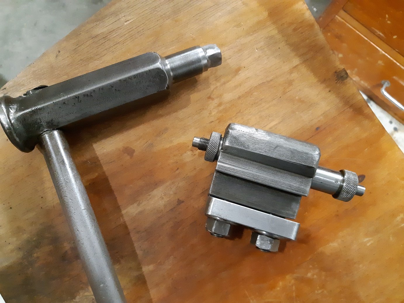
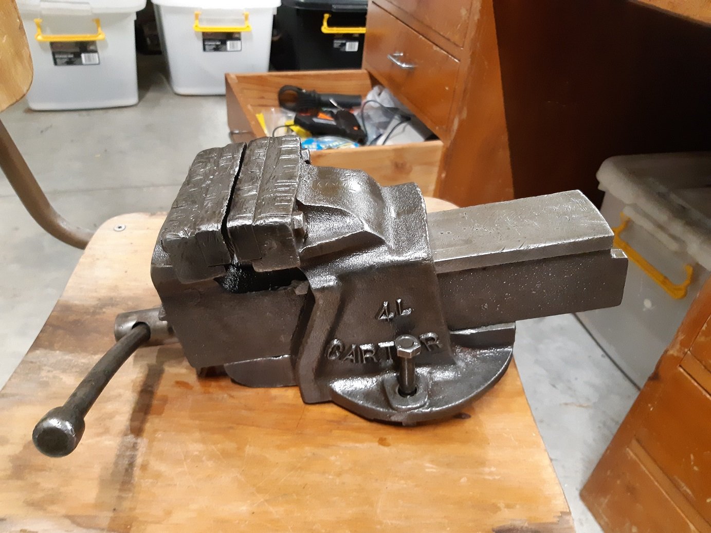
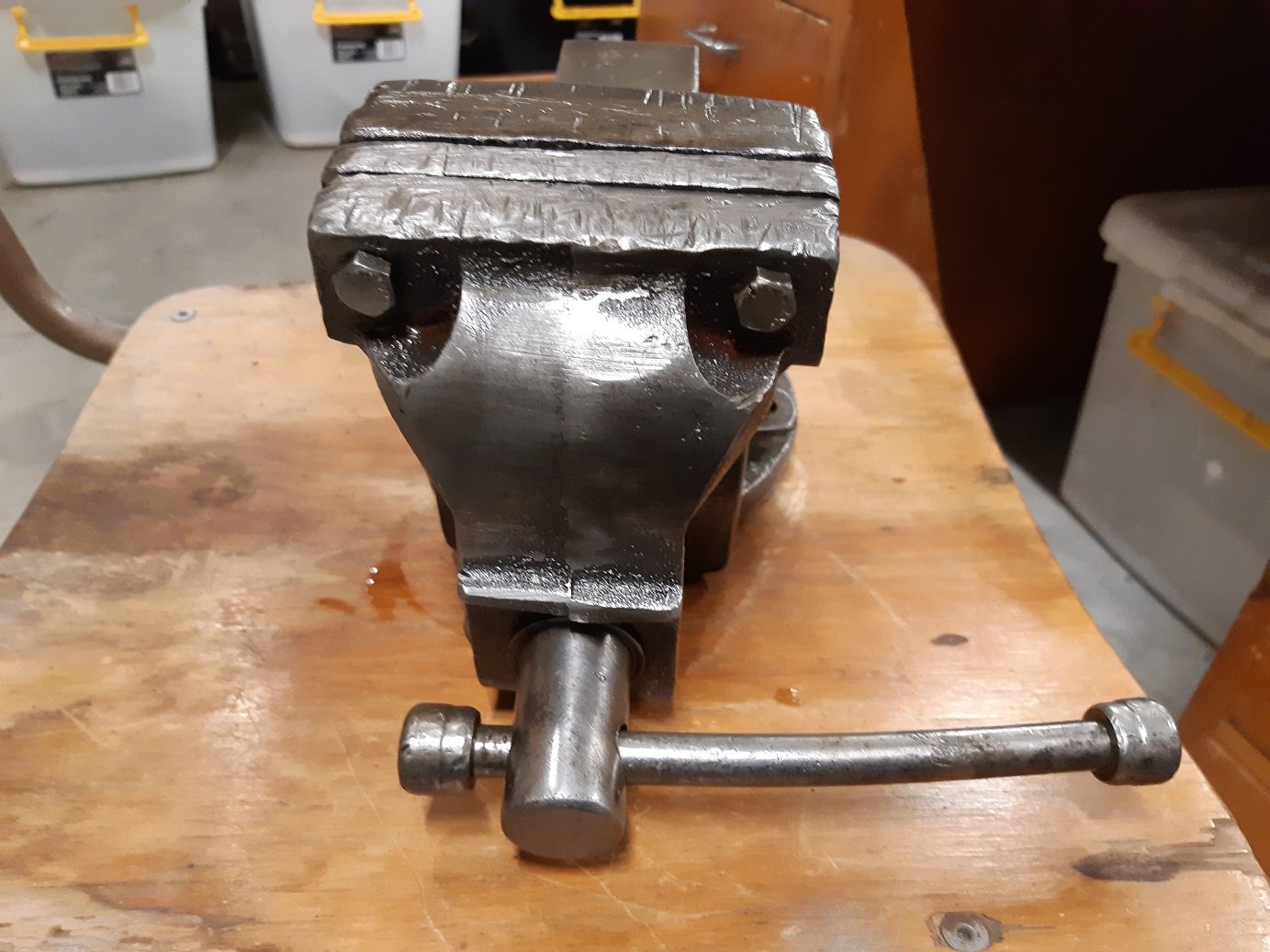
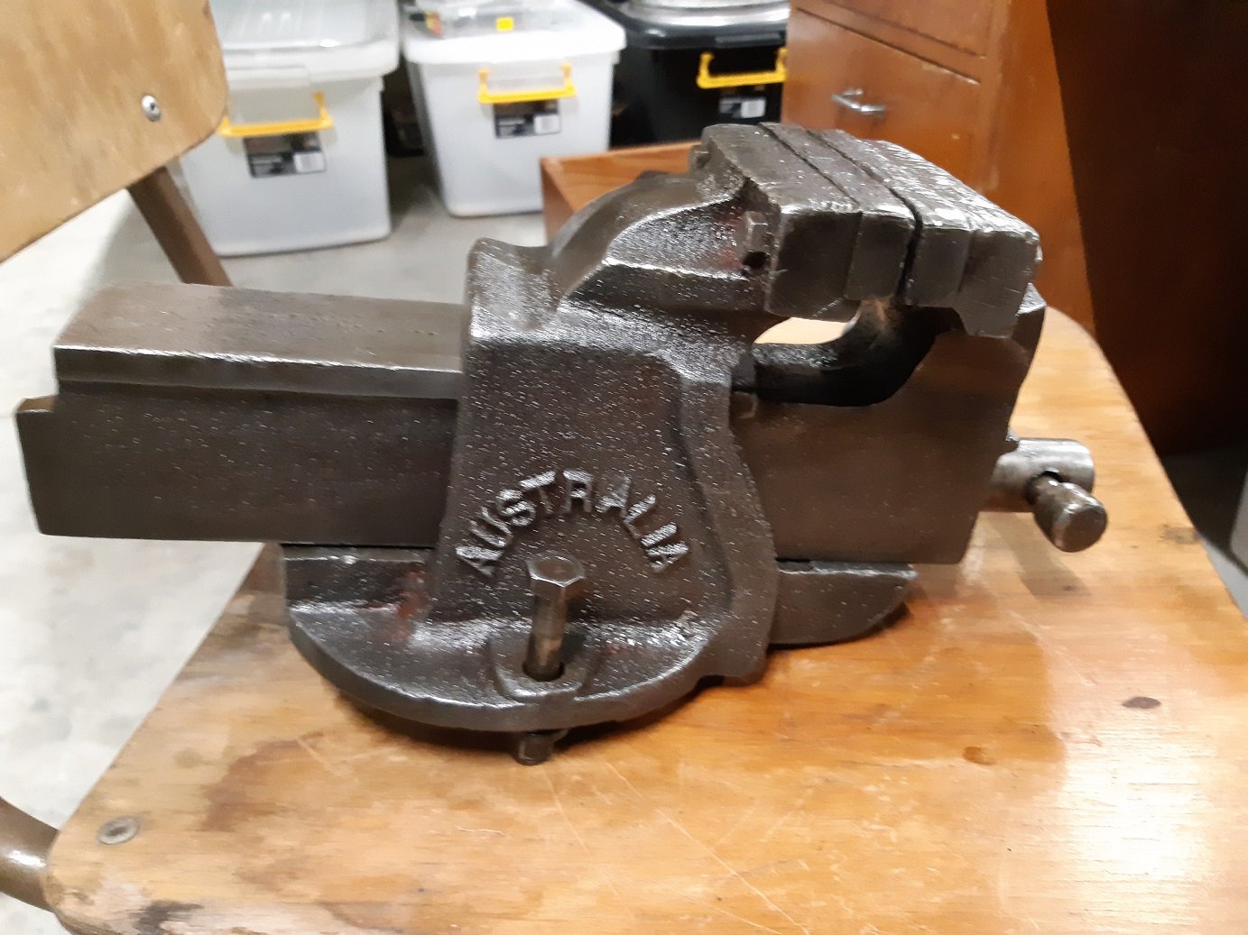
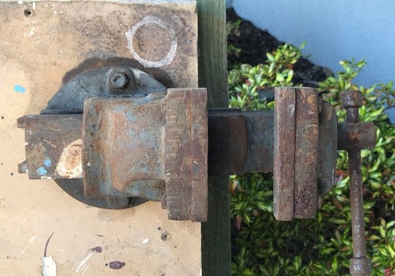
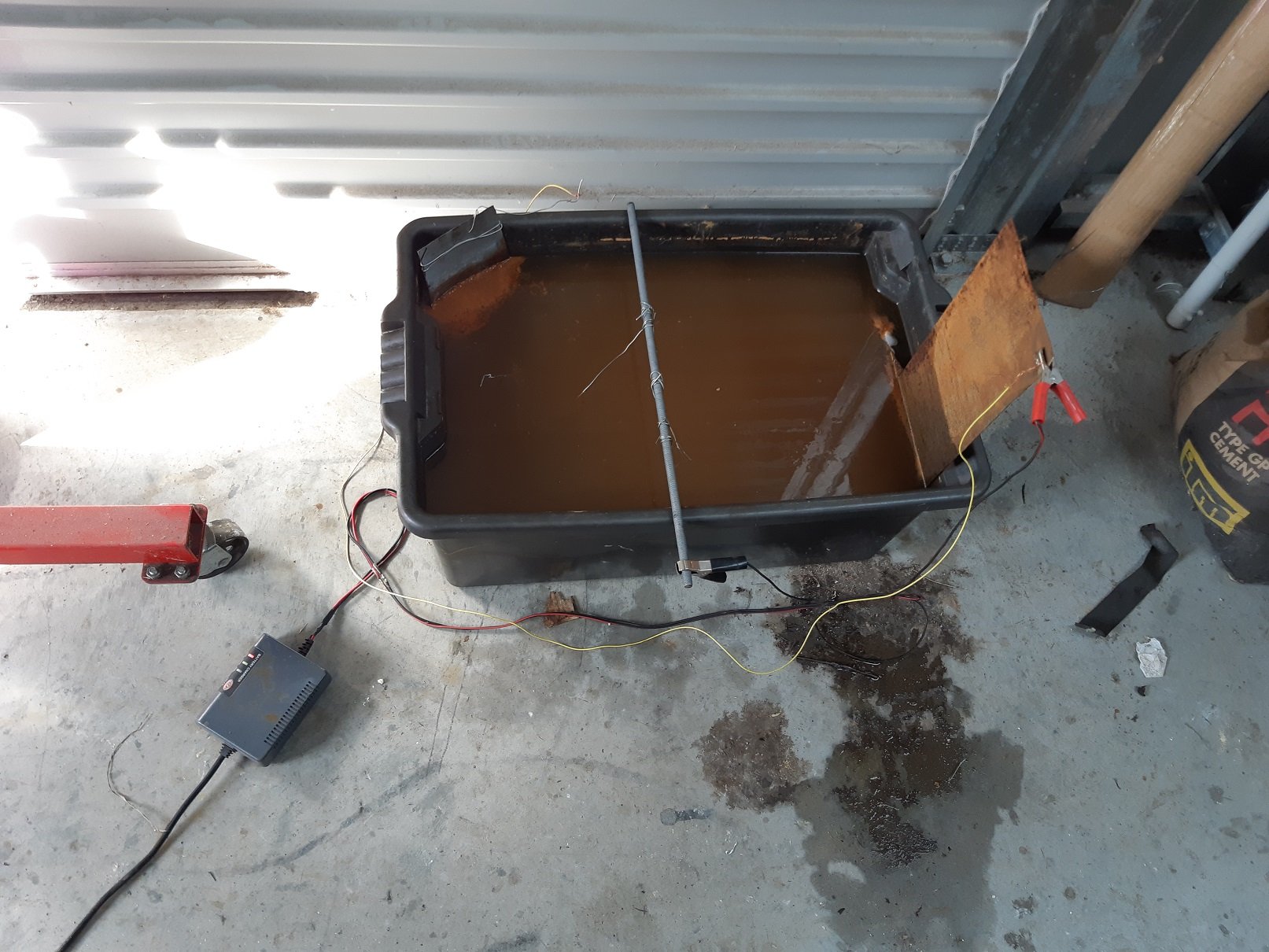
Today out of the electrolysis bath we have. The big chuck key and the vernier carriage stop. The carriage stop had filler/paint on the rough cast surfaces, but it was mostly chipped off. I decided to leave it bare metal and just rub it with oil. And not lathe.... but I got a little vice for $30 on trademe. I left it in the bath for a couple of days. Then used the wire brush on the drill. The casting was too rough to use the scourer pad. The casting is pretty rough, not much grinding/cleanup seems to have been done, so I suspect it was fairly cheapish when it was new.

- 72 replies
-
- 11
-

-

-
Oooosh. $125 space bucks! They are getting me one from another branch, only 3 out of 55 branches stock it.
-
Yarp, saw that. I'll try go to Ideal electrical at lunch.... but I'm on the bike, and it's pissing down.
-
It's off a compressor. So it's got a box on the top with the start and run capacitors, then a distribution block thing with 6 wires that go into the motor, so I suspect I will be able to reverse it.
-
So I'm trying to find some electrical switch gear. It needs to be able to handle >14Amps. I'm pretty sure it's not a good idea to use the switch on the wall outlet to turn the motor on/off. I haven't got around to actually checking, but I assume this isn't going to have a reverse gear. Reverse would be nice, so I'd like a reverse/off/forward rotary switch. I believe I know how to wire the motor to make it go in reverse. Finding an appropriate rotary switch is not as straightforward as I was expecting. I want to do forward/reverse and an emergency stop button(which could be part of an on/off switch). Does anyone have any suggestions of what to get and where to get it?
-
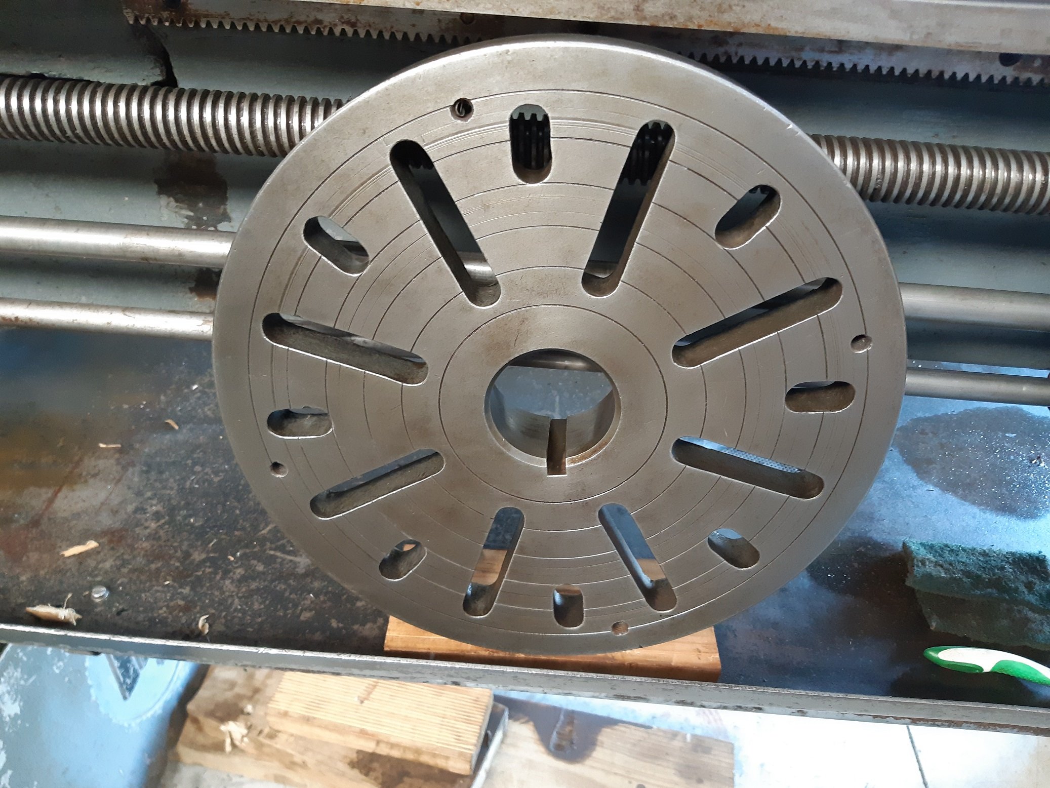
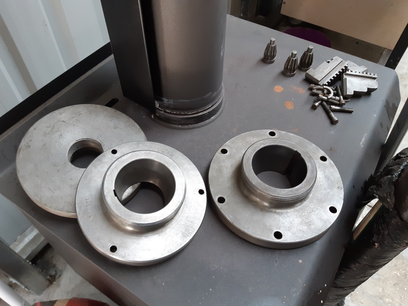
Cleaned up the big faceplate. I need to find a home for these things (close the the lathe because they are heavy).
-
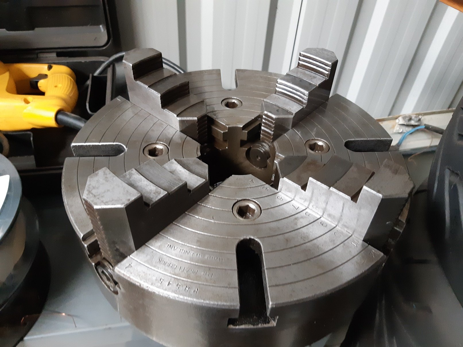
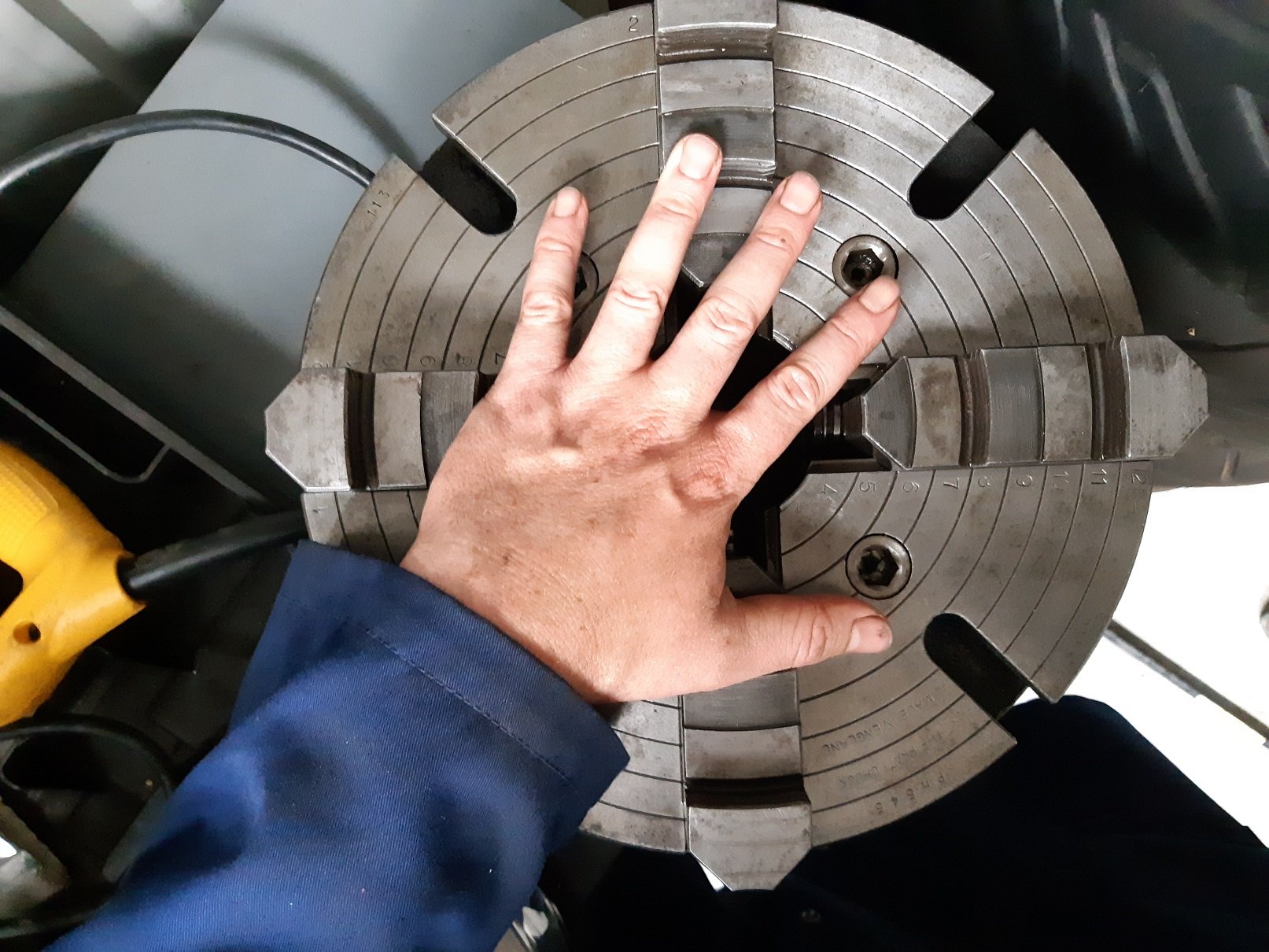
Electrolysis for the win. Ans a scourer pad... and soapy water. Came up well. I oiled the 4 jaw so it doesn't rust again.
- 72 replies
-
- 14
-
-
It's a taper lock pulley. But I found that I can just order the bush by itself with the correct bore for my motor. So just I've ordered that. ~$40
-
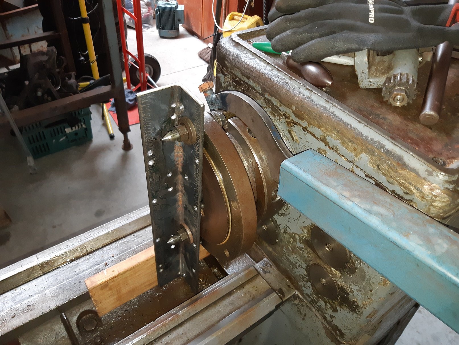
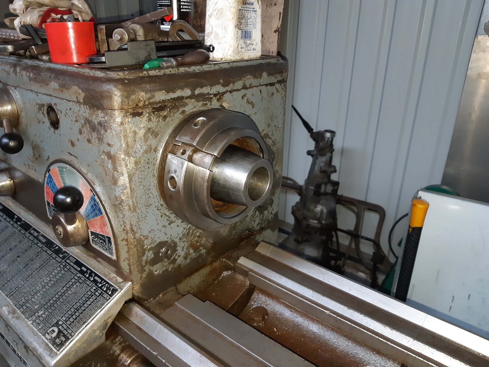
So the threaded collar that pulls the chuck mounting flange onto the spindle taper was stuck. The guy I bought it off said the previous owner also could not get it off and broke the big c-spanner trying to undo it. So this thing has been stuck for YEARS. I reckon some gorilla had been trying to "undo" it with a big fucking hammer..... the wrong way, so they were tightening it. Enter....ME. Right! big fuck off levers must solve this! So I tigged a 12mm bolt onto the c-spanner to fix it. Then made this no-turning-for-you thing. And put a long big of bar on the spanner handle. And discovered that my 82kg is insufficient weight to hang off the lever. So I swapped to the other side so I was lifting the lever up..... and proceeded to start tilting the lathe over.... Hmmmm Then I tried putting the trolley jack under the lever so the lathe was just starting to tilt, and whacking the collar with a hammer....Nope. So then I tried wedging a big bit of timber between the bed and the drip tray to give me a place to put a scissor jack. And jacked up on the end of the spanner. There was creaking from the jack and cracking from the wood. I got a whole lot of pressure happening and I was just waiting for it to explode in my face. I gave the collar a smack with the hammer and BANG! it fucking turned. HAH! It still didn't want to push the mounting flange off the spindle taper. So I started hammering on the back of the bit of angle. SUCCESS! The taper came loose and I could push it off by winding the collar by hand. It was a bit grubby in there. Here it is after I gave it a scrubbing with WD40 and a scourer pad. So the 2.2hp motor I want to try put on it has a 24mm shaft. The dual belt pulley that needs to go on it is for a 28mm shaft. I will try make a sleeve to make it fit. I'll also have to find a taller key.
-
Ah! I think the transformer is so you can have a 230 volt work lamp!
-
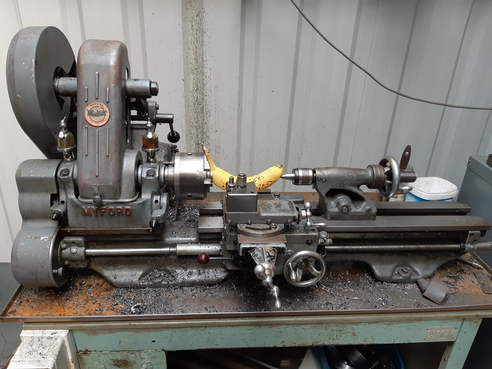
What size tooling did you use? It didn't come with any. Looks like maybe 25mm, or 20mm with a bunch of shims...
-
It was in carterton. Old guy had it for years. I think he said it was ex railways.. or some other gubmint place that has since shut down. There was another one on trademe recently. It looked exactly the same model. Same year even. It was in Hamilton. This one. https://www.trademe.co.nz/Browse/Listing.aspx?id=2362340323&archive=1 Is that the one you are talking about?
-
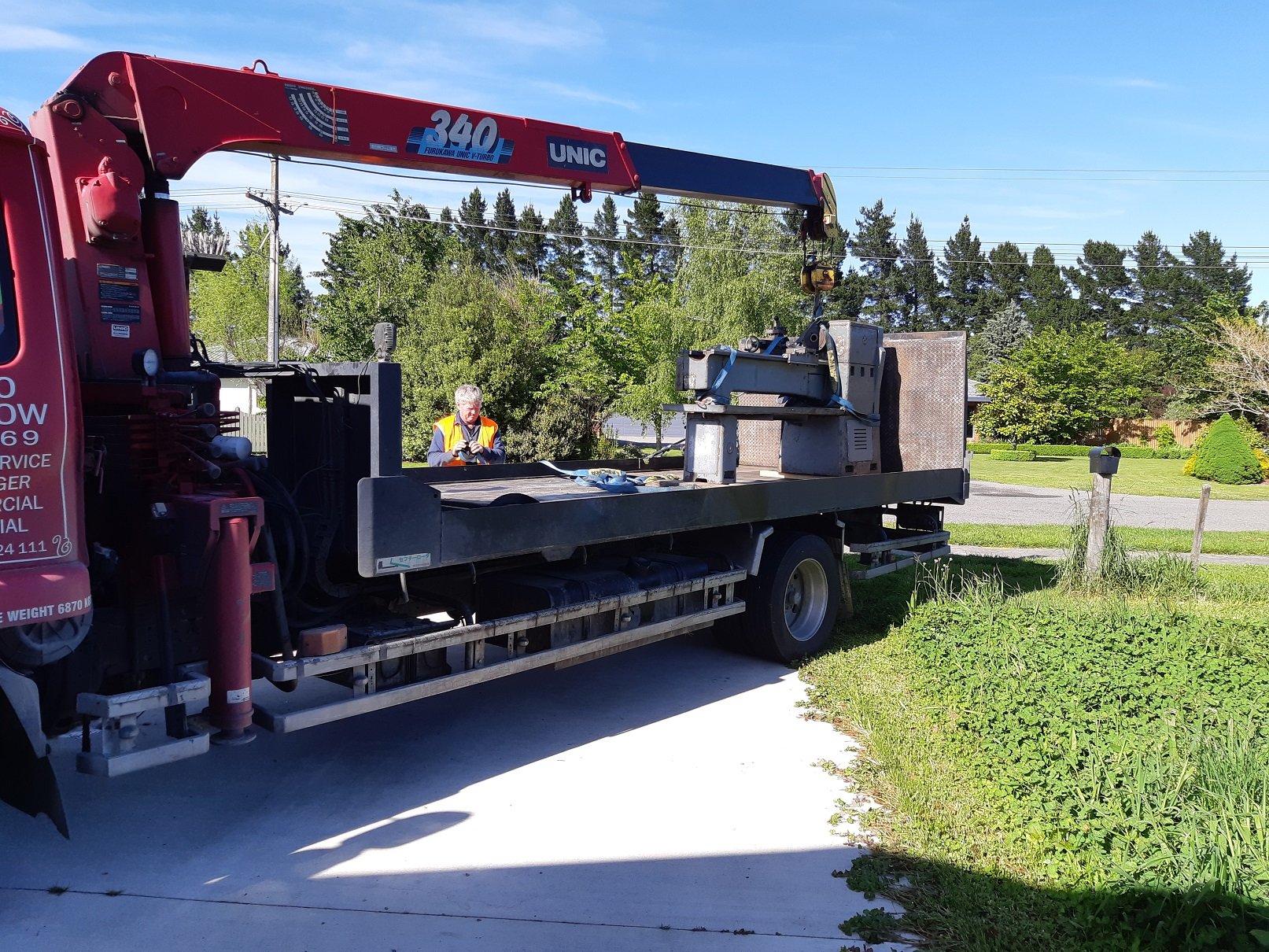
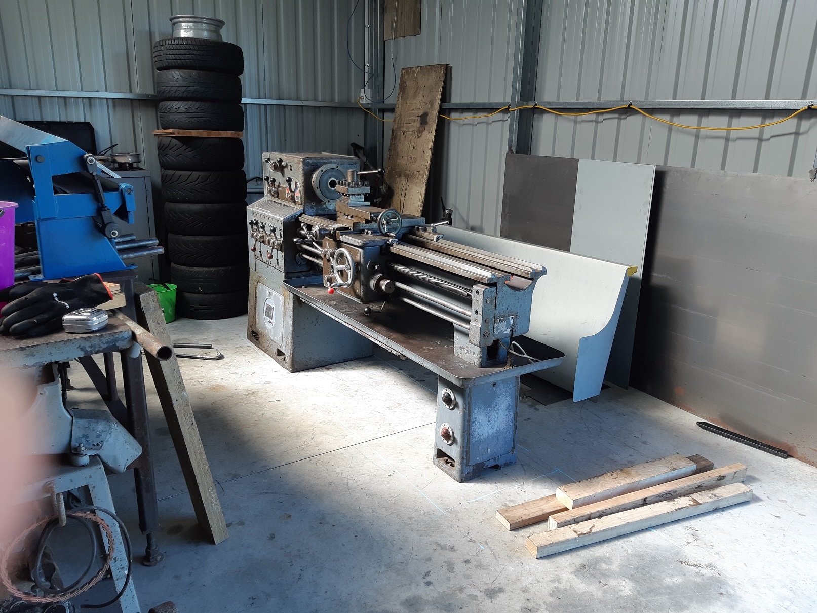
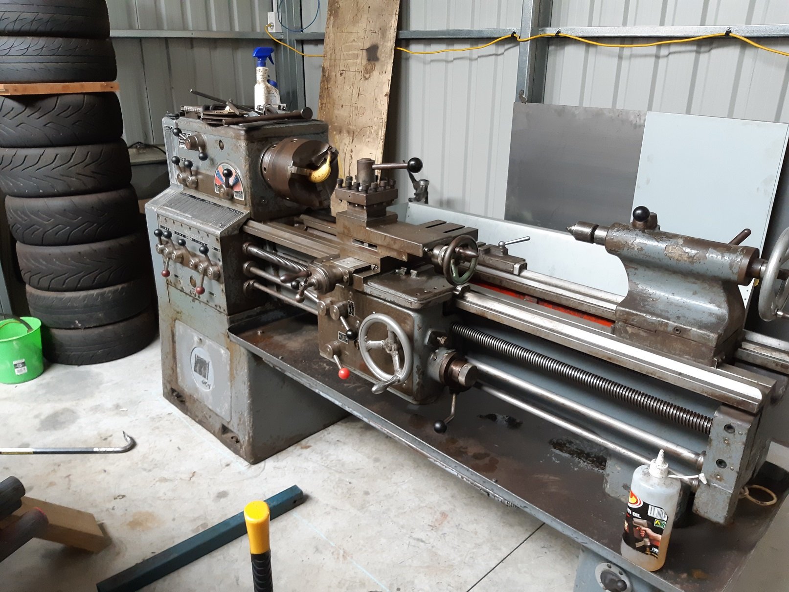
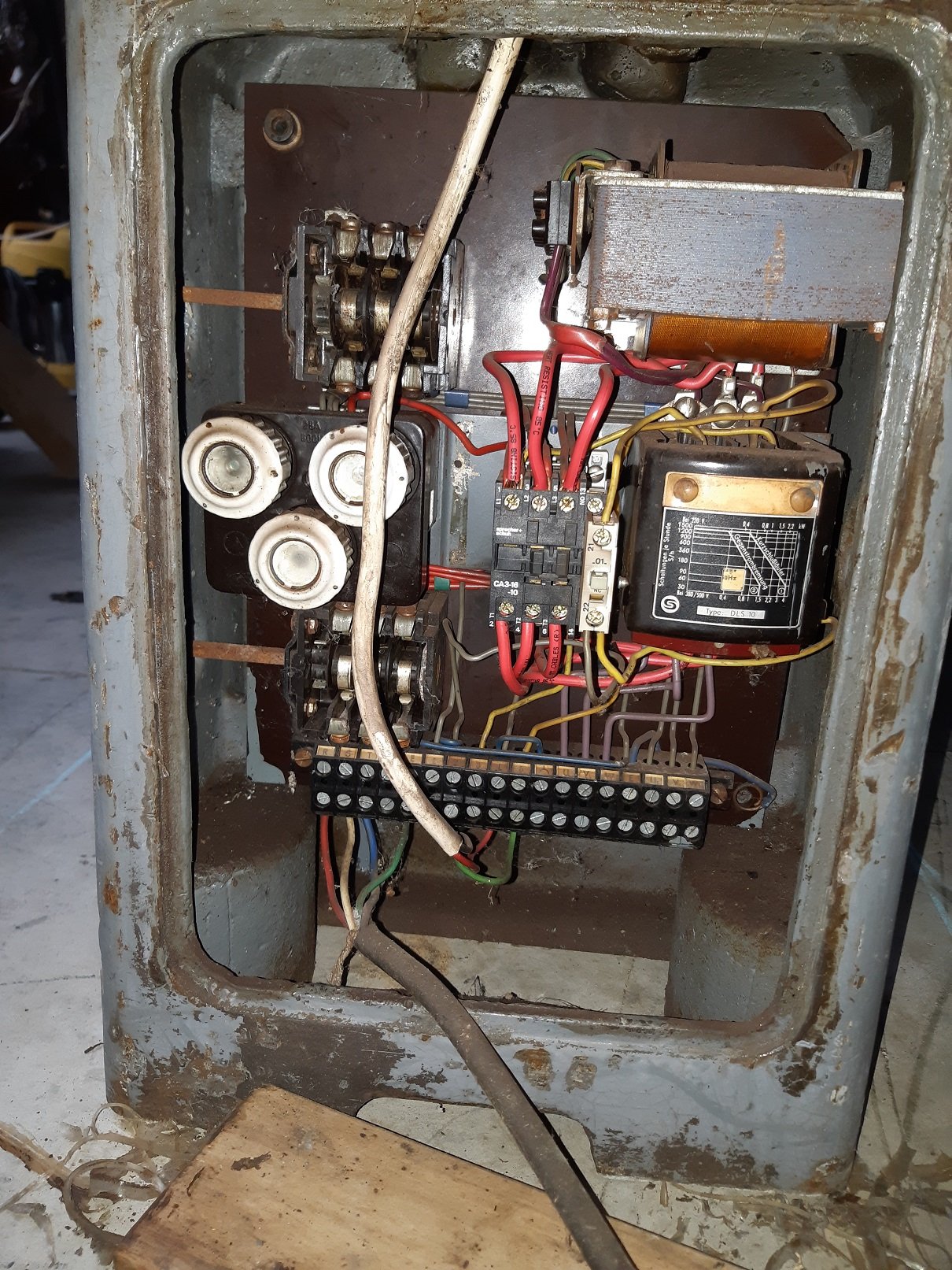
So I got this. It was so close to home, only 3.6km, I just had to click buy now. I got the local towie with his HIAB to pick it up and move it. It took ~1.5 hours. $120. We had to do a bit of manual handling because the truck could not get close enough and the crane boom was too high to fit in the garage door. At the pickup, the old fulla used/abused his engine crane to get it to the door. Then used the hiab to drag it over some bits of ply so it was close enough to lift. At my place, ideally he needed to park across my garage door.... but the driveway doesn't really let you do that. So we ended up with this compromise. My garage door is 3m, but the crane only barely could get under it. We got the headstock in, and placed it on some 25mm round bar. Then picked up the tailstock end and got it just in the door. Once it was in, I found it was pretty easy to roll on the bars. I took some size comparison photos to compare with the myford. And "What's behind the SCARY DOOR"? Buuuuuhhhh... Obviously it's 3 phase. It came with a motor, that was not installed, because he was going to install a different one. I'm going to see how I go with a 2.2HP single phase motor. I'll just wire it independently... But back to the scary door. It was sealed closed with some old as silicone. The black cable is the 3 phase feed. The white cable goes to two limit switches on two of the feed screws. The cabling to the motor comes out from behind this lot. The thing in the middle appears to be newer than everything else. As far as I can tell, it's an anti tamper breaker/switch, I believe the door presses down on the white bit when it's closed. That box to the right.... no fucking idea. Those three round things on the left... uuuh, fuses maybe?? There are two big rotary switches. Not sure what both do. I assume one makes the motor go. The other could be reverse maybe? They have no names, just 1 and 0. And a transformer. But why?? I've found fuck all documentation. I'm not even sure what the model is. They don't seem to have model numbers on their lathes. I suspect it might be a version of the M0 model.
- 72 replies
-
- 15
-
-
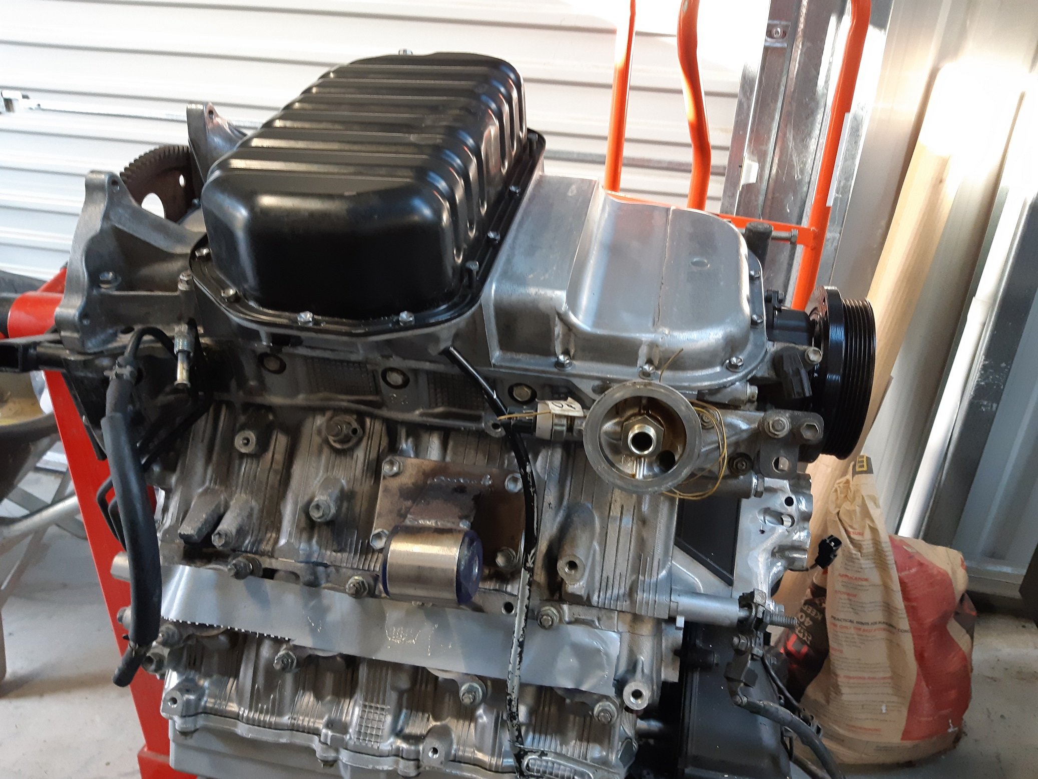
So since the engine mounts were welded to the chassis rails. And the modified sump is back on the engine. I suppose I can put the engine back in and figure out how much I can lift the steering rack back up. Shouldn't take long.... the engine was already on the crane. So I put the engine in the hole, I put one bolt through the left engine mount because that one got there first. Just lower it a bit more and slide the right side bolt through...... huh. The hole doesn't line up. It's off by 3-4mm... Is it just the urethane? I'll try align it with a big screw driver... Nope that's didn't work. Have the chassis rails spread?! Offers up front cross member. Nope those bolt holes still line up. Did I put the engine mounts on the wrong sides after painting? Surely not. Swaps mounts around. Puts one bolt through. Other side still still doesn't line up. And engine now tilted nose down. So I suspect, that when I removed the engine, then cut the temporary tack welds to prep for fully welding the mounts, I pushed the mount plates much more snug against the chassis rails so they were further apart. Disappointed... Simplest solution I can think of is to try shim the mounts off the engine block with washers to get the holes to line up again. Then I'll weld those washers to the mount so it cannot be installed without them.
-
Aeons ago, when I worked at Road and Track in lower hutt I got long wheel studs for my Starlet. "Nice" may have been the supplier, but afaik they came from a local stockist. Early 20's me though they were expensive at the time. Suspect it might have been ~$200 for 20. So R&T might be able to help.
-

Howat Engineering - widening steel wheels
Adoom replied to Beaver's topic in Lower North Island Region
Fyi: howatt works from his house now, the workshop was closed when i went there last. His address is on his website. Down near waterloo. -
That I would say is an EXCELLENT handle!
-
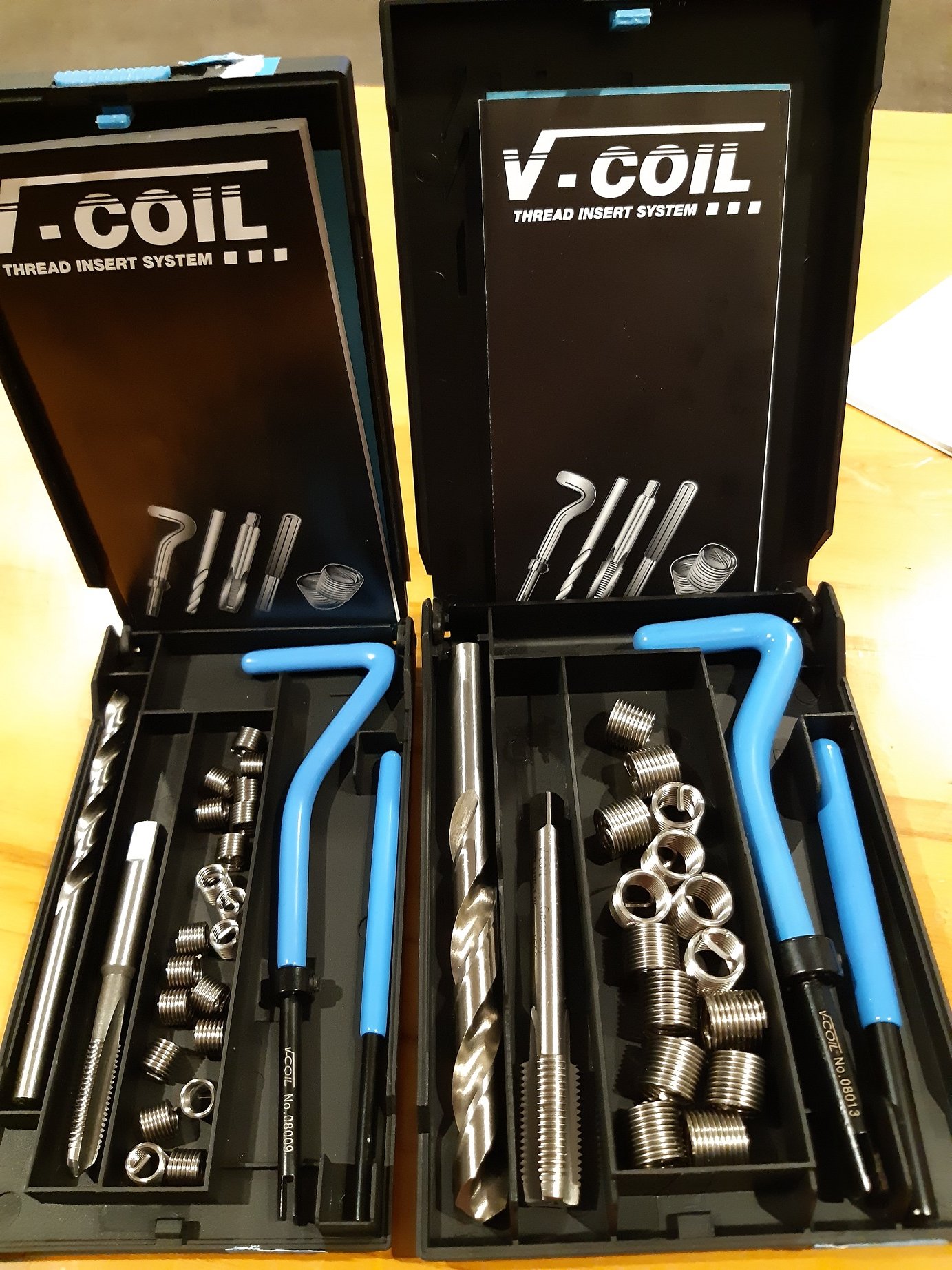
Sooo when I was chasing out all the threads I managed to put the wrong pitch M10 tap through one of the bellhousing mount holes. So had to invest in some thread repair kits. OUCH! My wallet. I got an M6 at the same time because there are some stripped threads on the gearbox. ...the gear lever retention plate thing is held down by four M6 bolts and all the holes are stripped.
-
Finally got the sump back on. Remembered that I had another set of bolts when I bought the sump so I cleaned them up.
- 191 replies
-
- 10
-
-
Who needs a welder? Sorry, couldn't find it in English.
-
Weld a handle on it.
-
WTF is an axle cross supposed to be? Do they mean the trailing arms??? They are more of an "L". How is it for rust... Battery fallen through the battery box and dangling? Rear subframe mounting points loose/broken? Broken exhaust mounts? Probably this one I reckon. Not much else under there that could make a knocking like that.
-
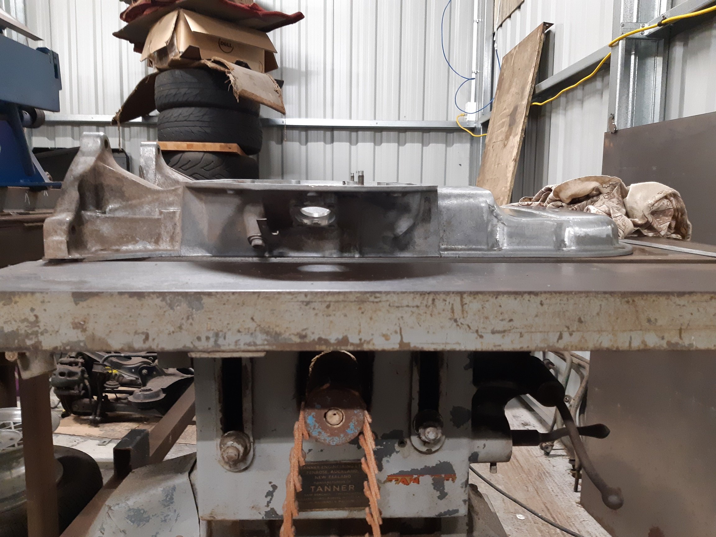
So I found a local place that could anneal my sump which would allow me to pull it flat. Dymo Manufacturing in Wingate. They put it in their kiln with it bolted to the jig. It was heated up to.... hot, then allowed to cool down slowly over many hours. ~10 I think. $70. The heat seems to have baked out any oils and cooked the sealer that was still in the grooves on the mounting face. The sealer just crumbles and turns to powder when I scrape at it. Only down side was it caused some of the small M6 bolts to seize in the jig which I wasn't expecting, so I broke one and stripped at least two more. So I'll have to find some suitable bolts to bolt it back to the engine. Oops. But it's more or less flat already. So I am happy to bolt it back to the engine, the sealer will sort out any tiny gaps. Cast iron table saw top is the flattest thing I have. I did try move it around a bit, just in case the table saw top was bent. It's the same which ever way I put it. There is still a tiny gap at the front of the sump, but it's no bigger than 0.5mm and if I put some weight on it, it closes up. Yay.
- 191 replies
-
- 18
-
-
You got it. The top wheels are a little smaller that you have drawn. The bottom wheel is about right. I think the blade is 0.6mm
-
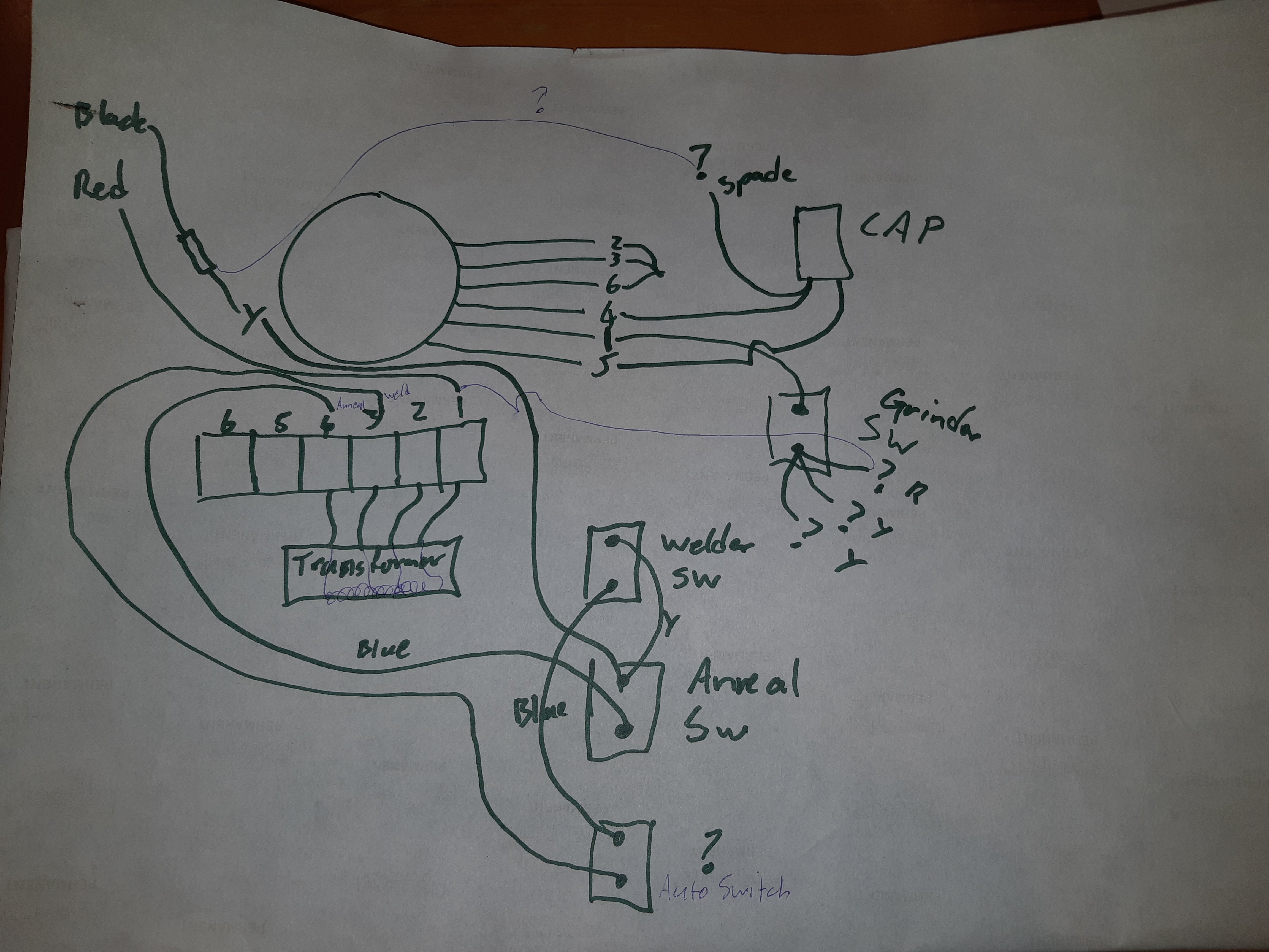
I gave the welder assembly a clean with compressed air. It had loads of metal 'dust' all over it. Which I assume was conductive! I should probably try make some kind of plastic dust cover for it. I traced the wires... Round thing at the top is the grinder motor. 2,3,6 are joined together, which looks original. As far as I can tell, the welder and annealer should have been working, it was only the grinder motor that was no longer connected. AFAIK, if I add in the wires I've drawn in thin lines, the motor should work. So next thing to do is pull out the multimeter and check the switches all work and there is continuity in the transformer coils.