Adoom
-
Posts
2,279 -
Joined
-
Last visited
Everything posted by Adoom
-

Random slightly cool stuff you built but not worth its own thread, thread
Adoom replied to h4nd's topic in Other Projects
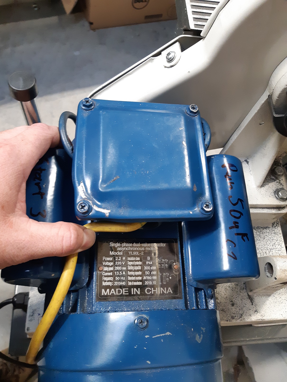
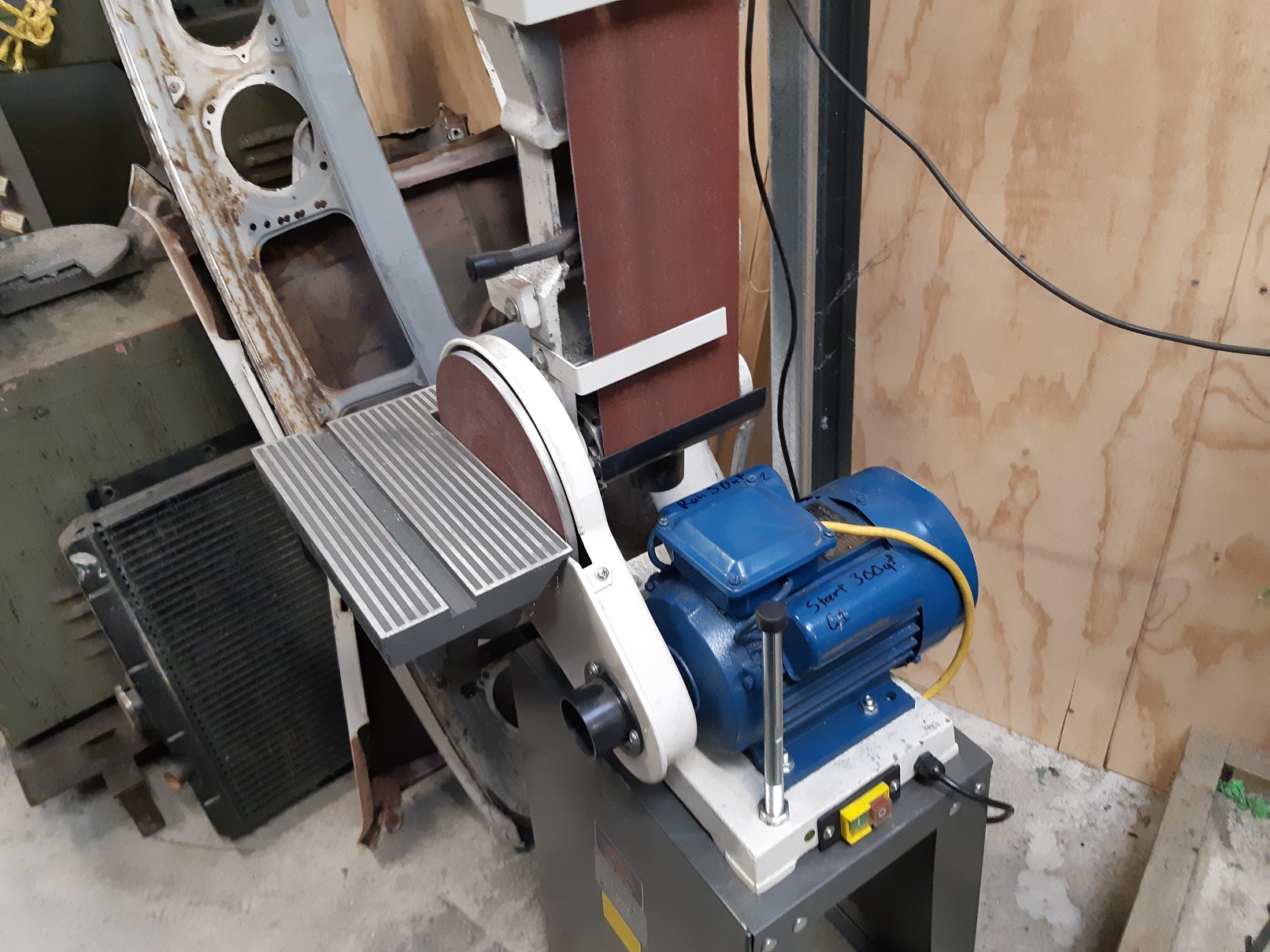
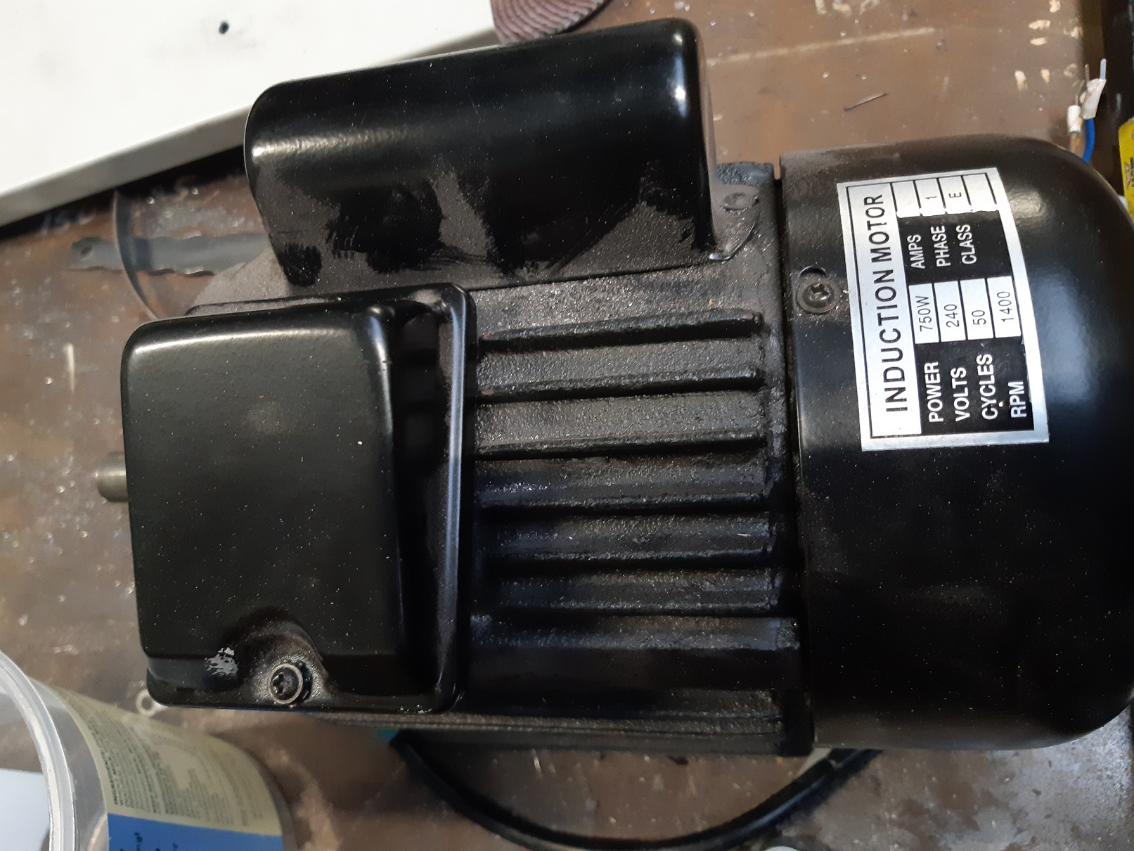
I bought a ToolShed linisher/belt grinder/sander thingo a while back. It had mediocre performance and it was easy to stall the belt. It came with a 1HP 1400rpm motor. Boooo! There! I've fixed it! YAAAAAY! Three times the power and double the speed should do it. The belt guard is off here. It's a bit shit and rattles and vibrates. It's almost as if they forgot to add fasteners to that lower bracket. I'm gonna sort that out. Should be able to flatten my exhaust manifold flange now.
-
It will be WAY easier to get at from the back.
-
I'm having difficulty imagining this thing you describe.
-
I'd aggressively scrape at it with a screwdriver you don't like much or some other sharp pointy thing so you can see how bad it is. If it's just light surface rust you could clean it up real good and paint over it. Epoxy if you have it, but something like hammerite is probably good enough. If there is any pitting, and definitely if there are pin holes, I'd want to cut that out and weld a patch in. But I've had a bunch of practice welding panel steel.....
-
Trying to fix rust in that area is a pain in the arse. Take out the dash or just the glove box and access it from the back. Mine looks a bit different because it has the heater inlet holes blocked off because racecar and it seemed like a good idea at the time.
-
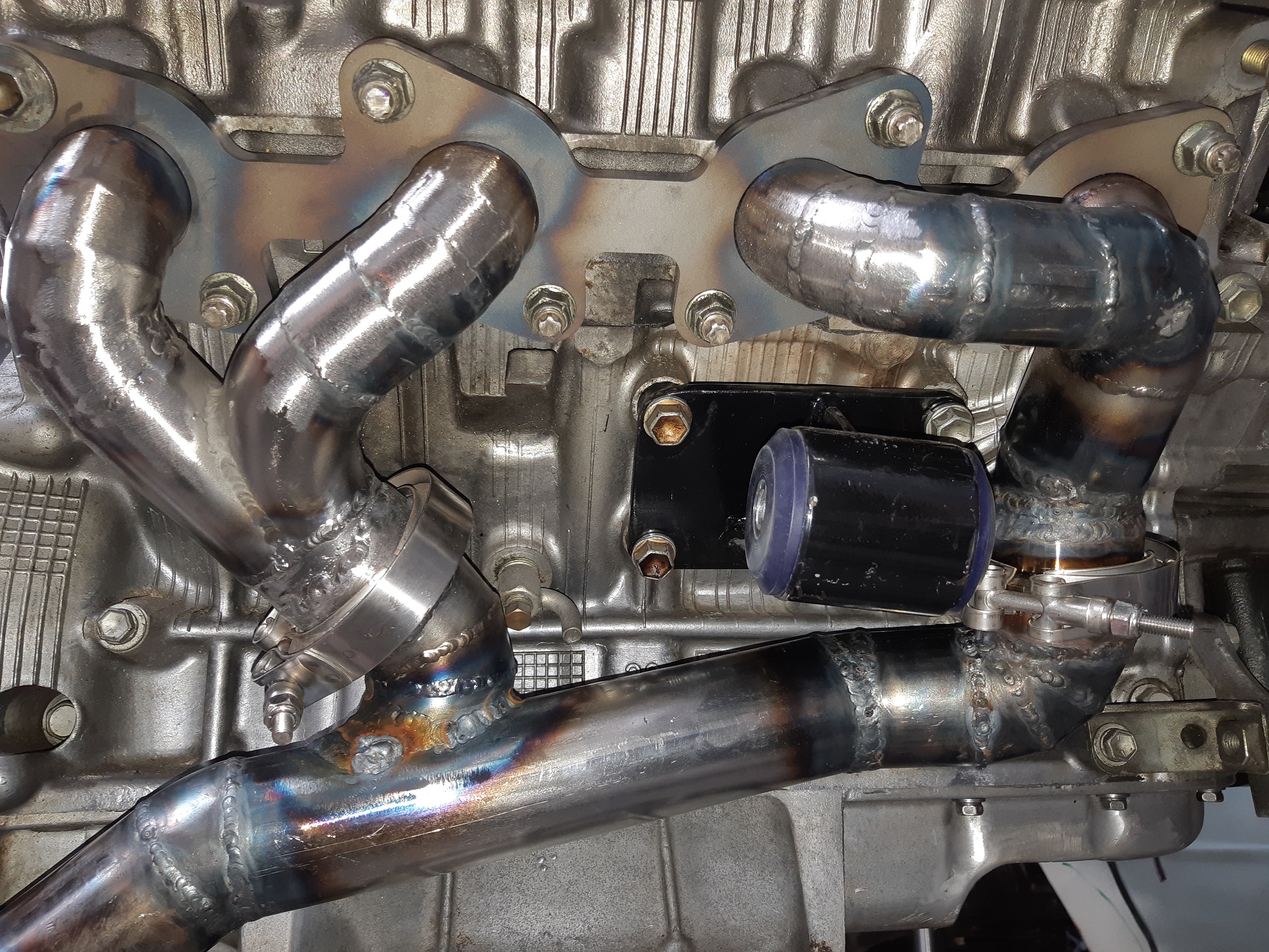
Leak test identified that the rear v-band on the drivers side was not sealing. I tried cutting and realigning with no luck. I changed the design to use only one v-band. Hopefully it's all good now.
- 201 replies
-
- 11
-

-
Done. I suppose I should do some kind of leak test since there are eleventy billion welds on this thing. I also learnt that if you use the cordless drill on the nut for the v-band clamps, and there is no lube, and they are stainless, the thread eventually galls and welds itself on. Fortunately, my original design was going to use more clamps, so I had a spare. But still, they aren't cheap. I put a drop of oil on the threads now.
- 201 replies
-
- 17
-
-
Sprayed myself with sharp metal filings whittling the hole out with the die grinder. I also welded it on the back side of the head flange. But it was shit and bubbly... probably should have cleaned it. I'll have to grind it out and do it again.
- 201 replies
-
- 11
-
-
Managed to fit it all in. I had to put the v-band flanges in the lathe to make it shorter. Need to scribe around it, then cut those spot welds and whittle out a hole
- 201 replies
-
- 11
-
-
A some more. This shit takes fucking ages. It took me literally four hours of going from engine to bandsaw to sander to wire wheel to grinder to welder to sand blaster to wire wheel to engine to bandsaw to sander to welder over and over and over just to make this small bit.
- 201 replies
-
- 21
-

-
-
Did a bit more.
-
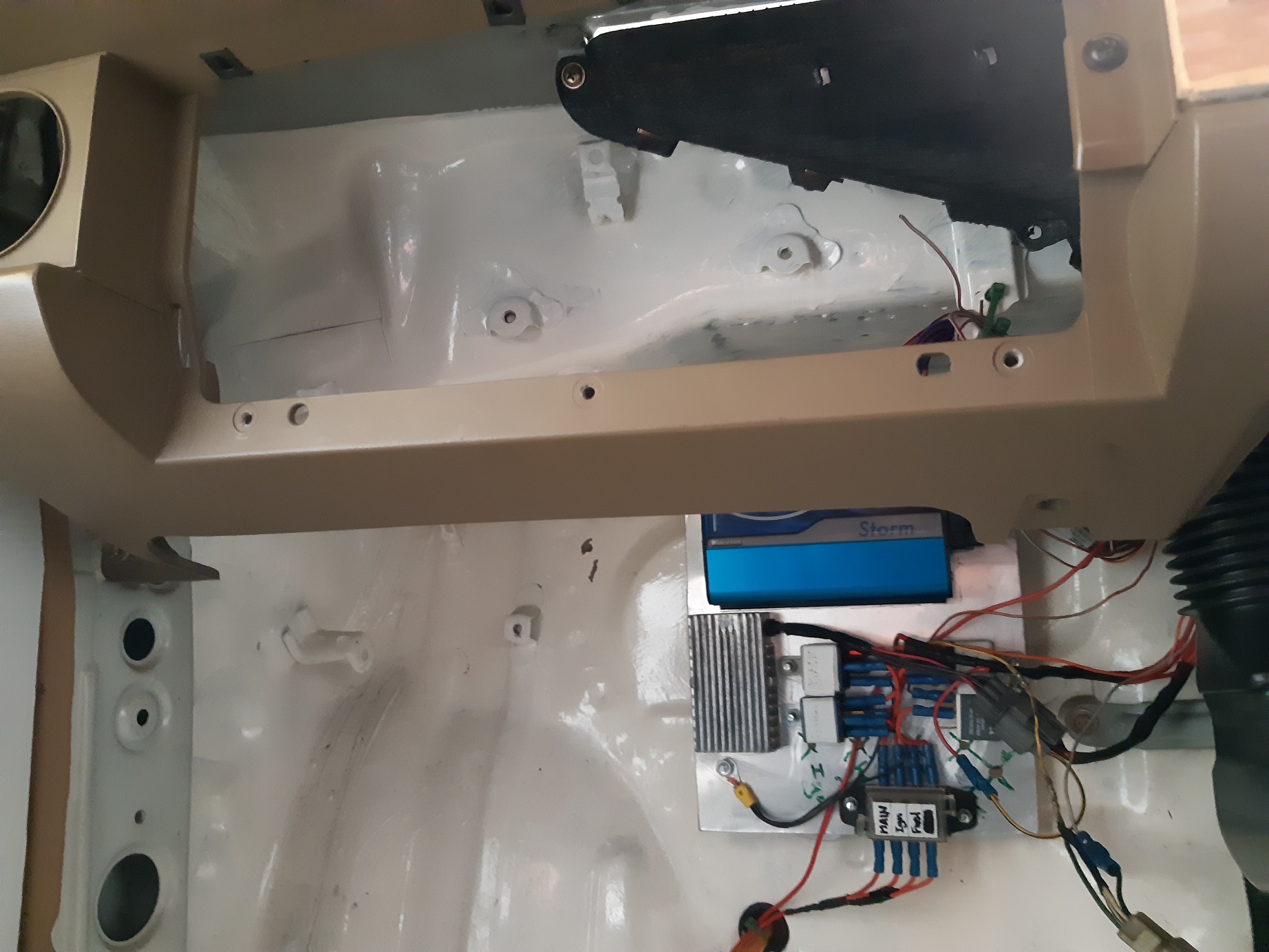
If the Atom has enough spare inputs/outputs, you can us that to control the water injection and you don't need a separate controller. Since the Atom already knows the inlet temp and the boost pressure from the map sensor, you probably just need one Digital Out to turn the water injection sprayer on.
-
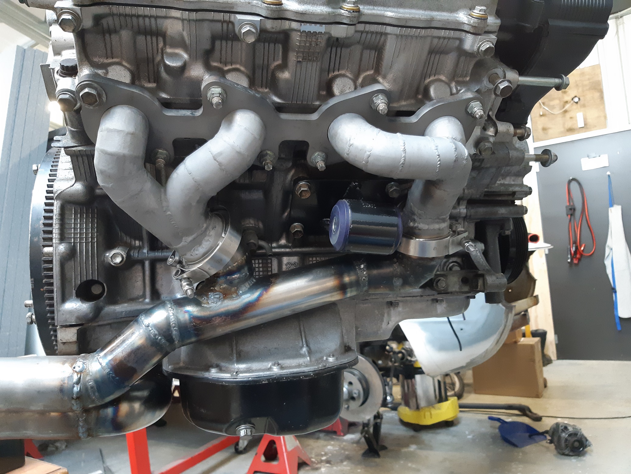
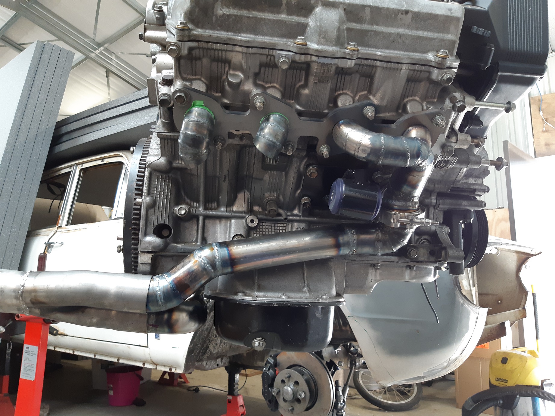
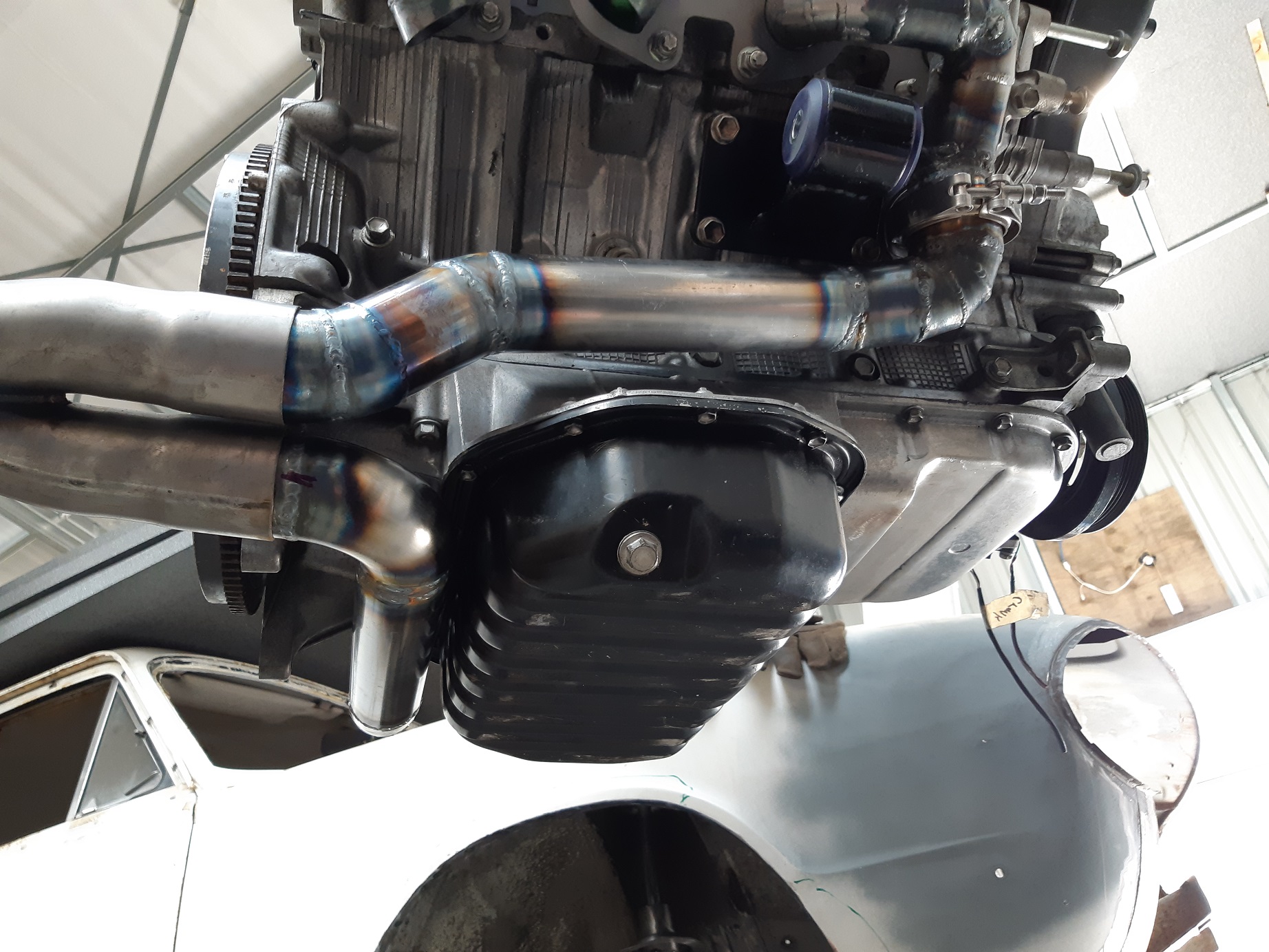
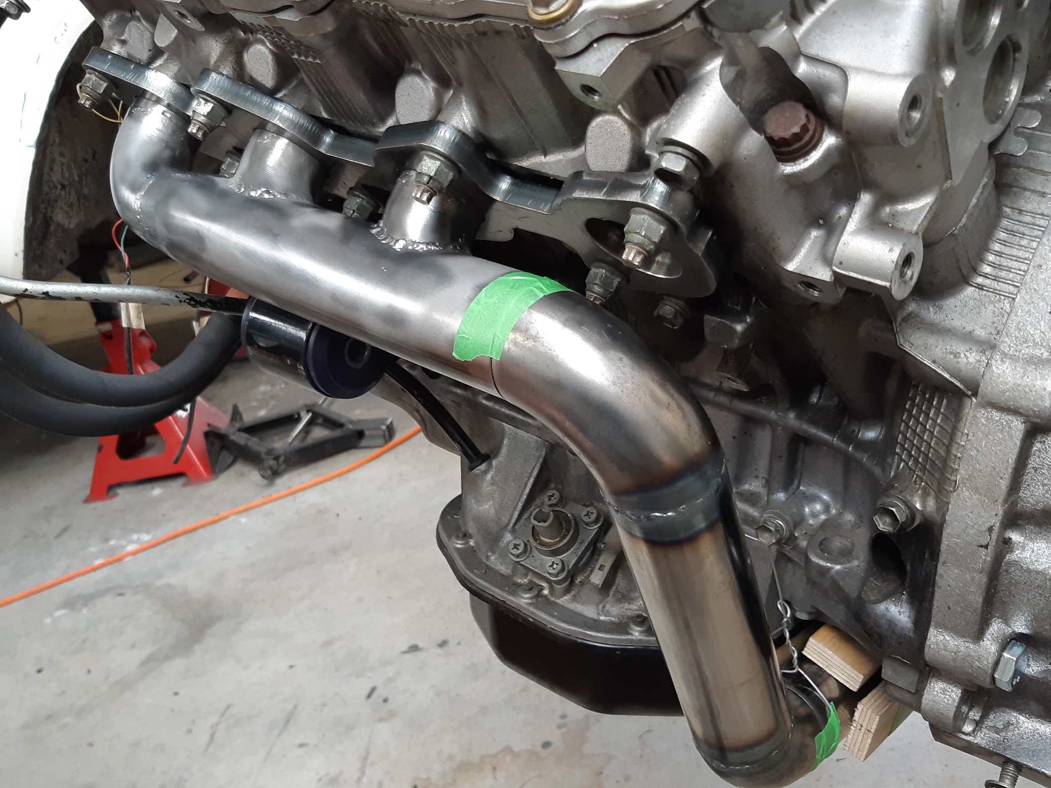
Yep, it needed a kink put in it. Even like this it just misses the corner of the chassis rail by 5mm. Not sure if I will need to relieve the chassis rail by taking the corner off it. I'll see if I can get the engine to rock enough to hit next time it's in. Hopefully it doesn't, the urethane engine mounts are pretty stiff. I've still got to fill in the blanks on this side.
- 201 replies
-
- 14
-
-
I experimented with water injection on my CA18ET. Ended up trying E85 in the water injection system. But the flow rate was inconsistent. Replaced it with an EFI pump and a small fuel injector. It worked really well. It only came on at higher boost levels, it allowed the 'normal' fuel to be reduced because of the added E85 and the timing increased. It dropped the intake temp by quite a bit. Went from 150kw to 170kw without changing anything else. It used fuck all E85. I think I worked out that if I was on boost 100% of the time, the 5L of E85 would last about as long as the 40L 'normal' fuel. Buuuuut something went wrong, maybe the E85 injector blocked, or probably fuel distribution was uneven between the cylinders because of where the injector located in the intake pipe. So I got real bad detonation at the track and destroyed the engine. If I had to do it again I'd want some knock detection. Or run a 2nd set of injectors to ensure even distribution. I replaced the engine with a CA18DET. Made 190kw on less boost with normal fuel.
-
I need to put the engine back in the hole to make sure this clears the chassis rail. I suspect I may need to kink it so it's closer to the block.
- 201 replies
-
- 12
-
-
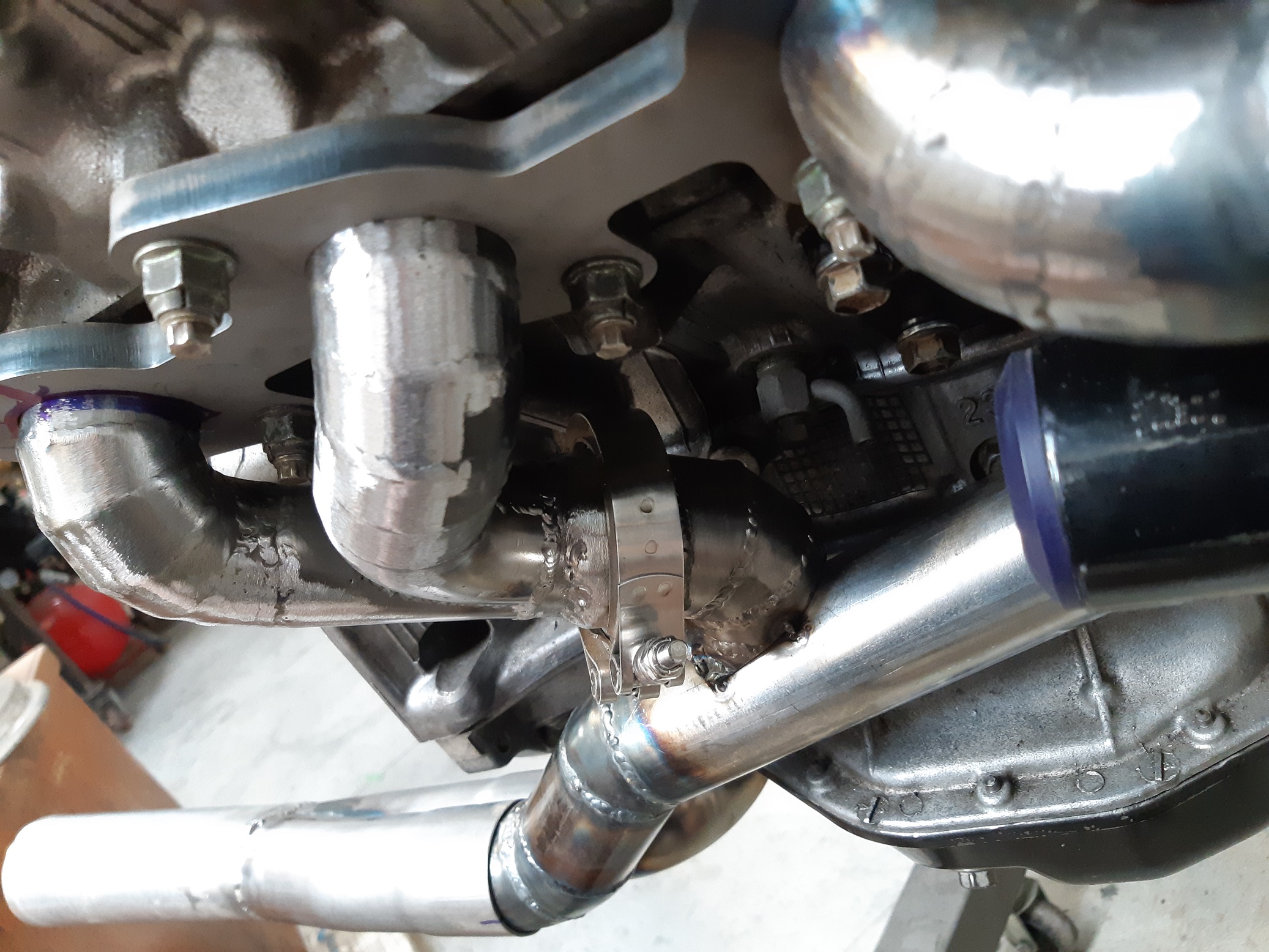
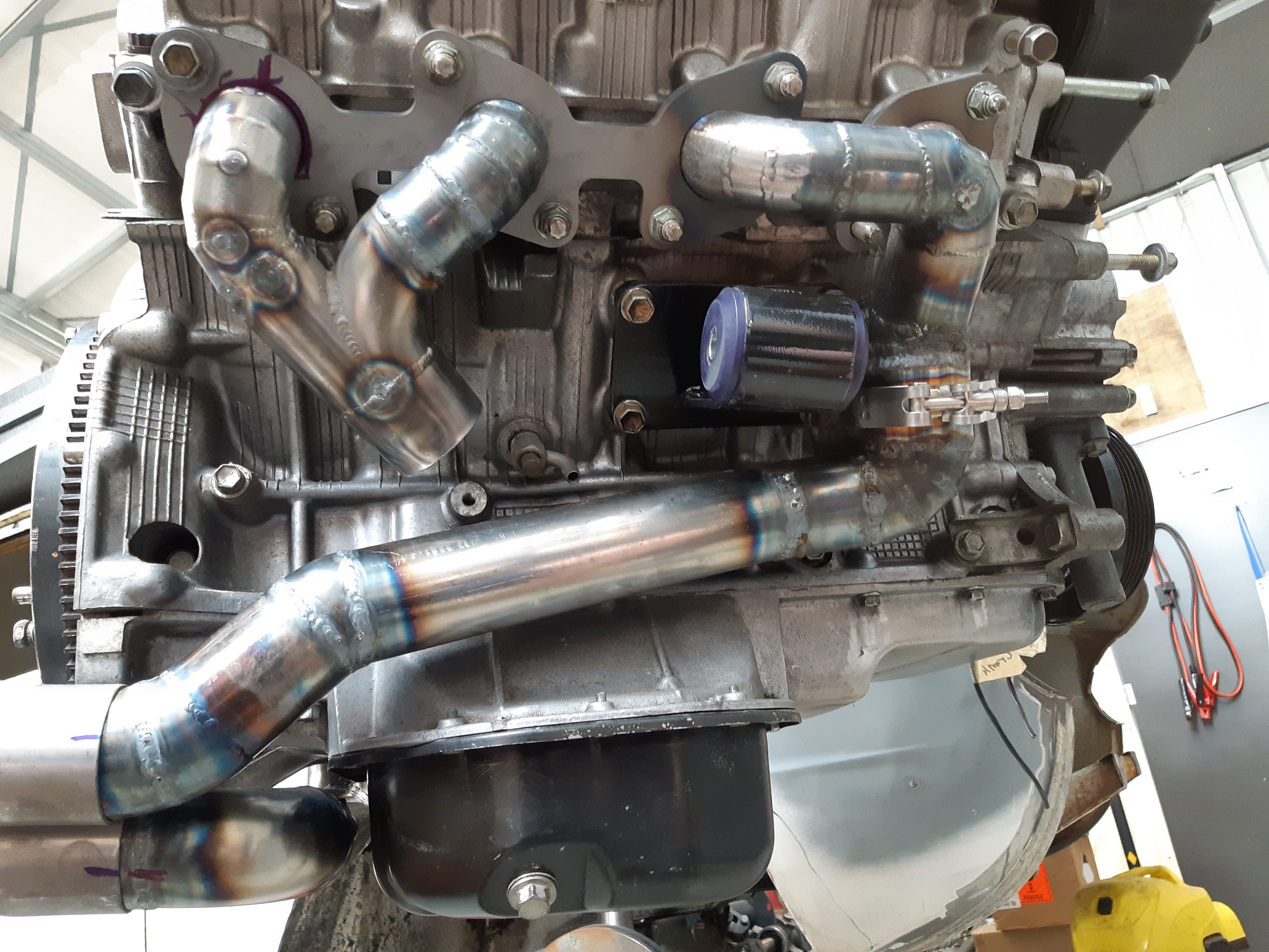
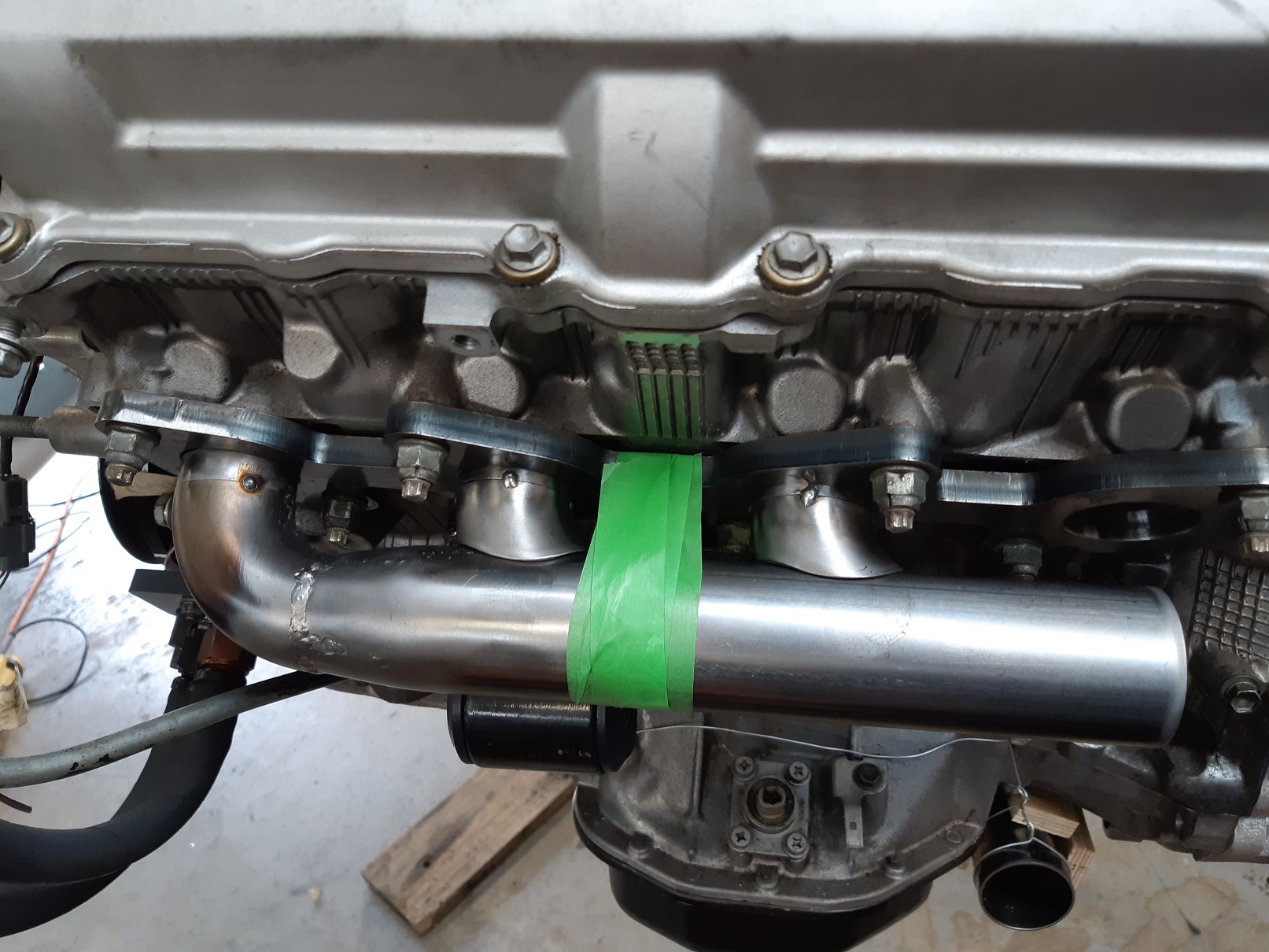
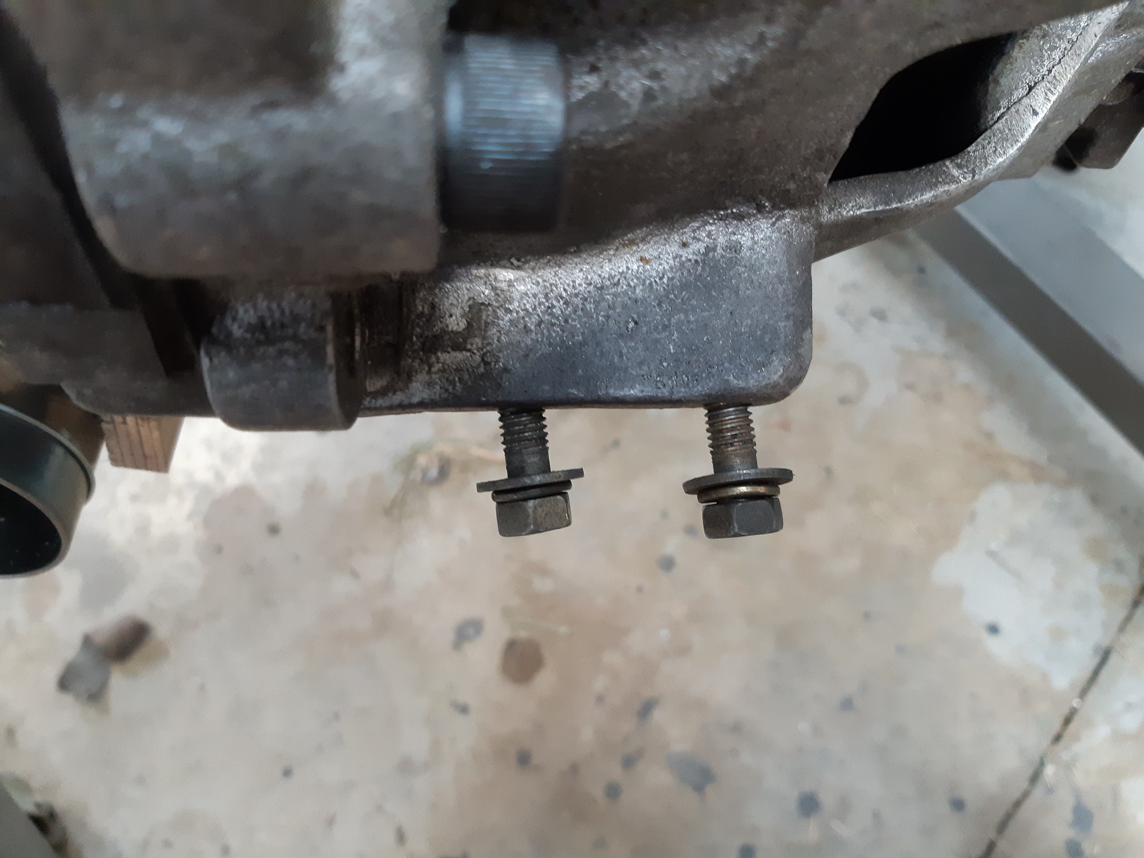
Since you guys insisted I use mandrel bends for the short runners rather than straight pipe, here you go. The first one didn't quite fit but I covered it in masking tape to make a template that was more or less the correct shape. I've still got no tig gas, so used the mig to tack it together. I used some hitech spacers and mounting solution for the cross over pipe. The last runner is going to be a real bitch to fit because it needs to merge right in the middle of the larger bend. The downpipe will have a v-band somewhere. I should probably put it back in the car while it's only tacked together, to check it still fits. I also happened to notice this atrocity which is the clutch slave cylinder mounting bolts. I assume it was like this from new..... so someone paid ~$700 for this niteparts(?) bellhousing and was apparently all cool with these cockeyed bolts. I'm not cool with it, I've got to find a way to fix that, it's fucking terrible.
-
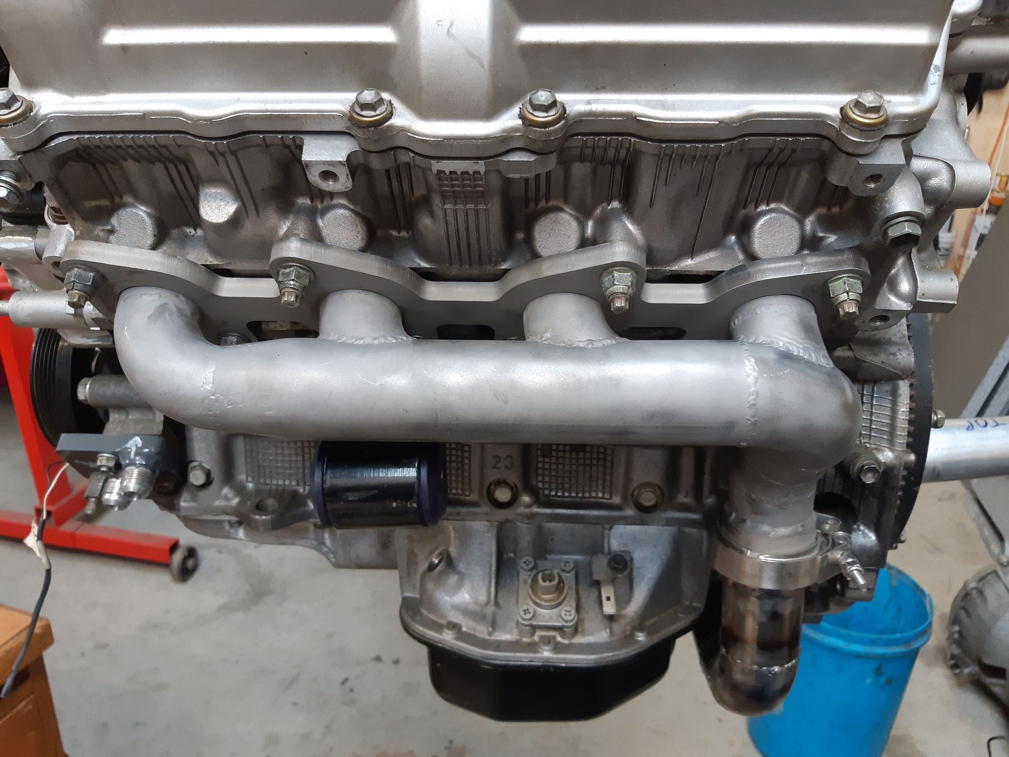
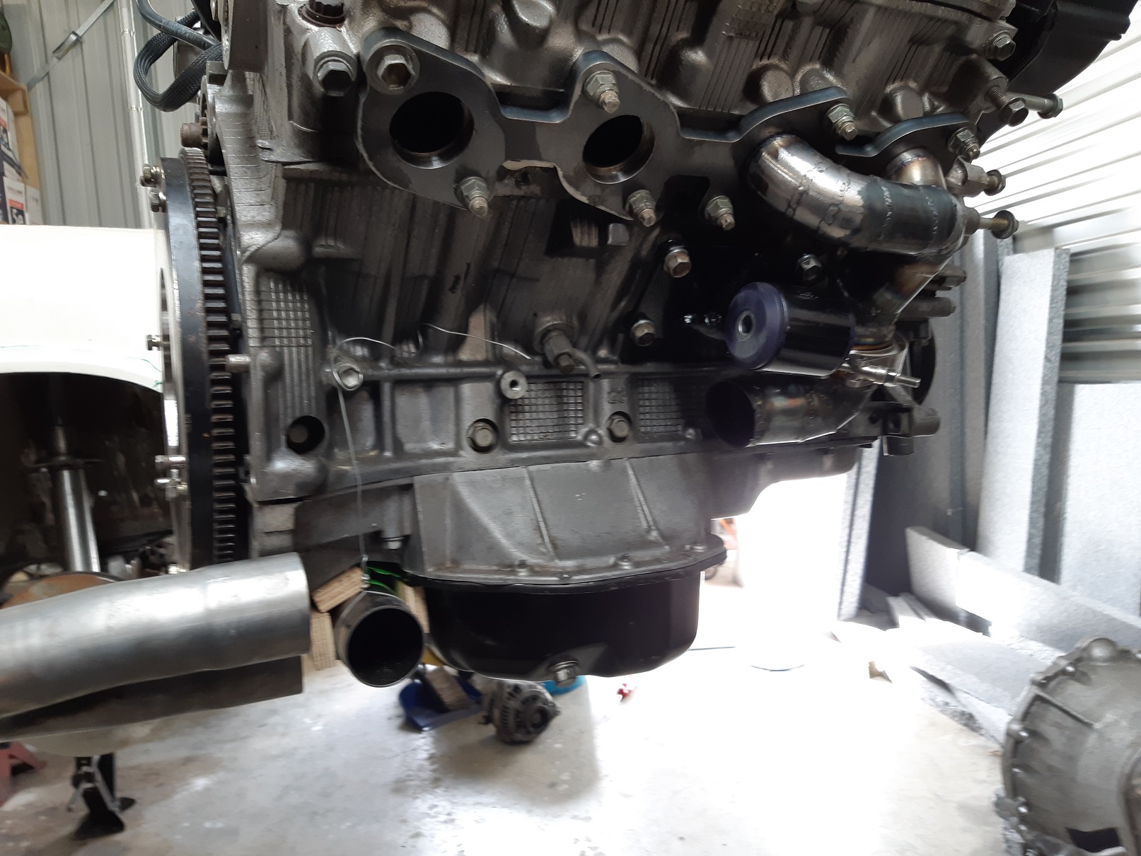
Got some motivation to continue with the exhaust manifold. I'm just gonna do a log on the passenger side because there's no steering shaft to try get around. Hopefully that doesn't make the exhaust sound weird. Did just a little bit of welding and realised Argon is on empty! Fuuuuck, I only just filled up the week before xmas. At 8L/m that's about 3.5 hours of solid welding.... have I really done that much?! Not sure if it's worth the effort of using mandrel bends for the two middle runners.... they will only be 15-20mm long... is it going to make any difference if I just use straight pipe. I made a cone to step up the size, looks much better than that factory one where it seems like they just fill the gap with weld.
-
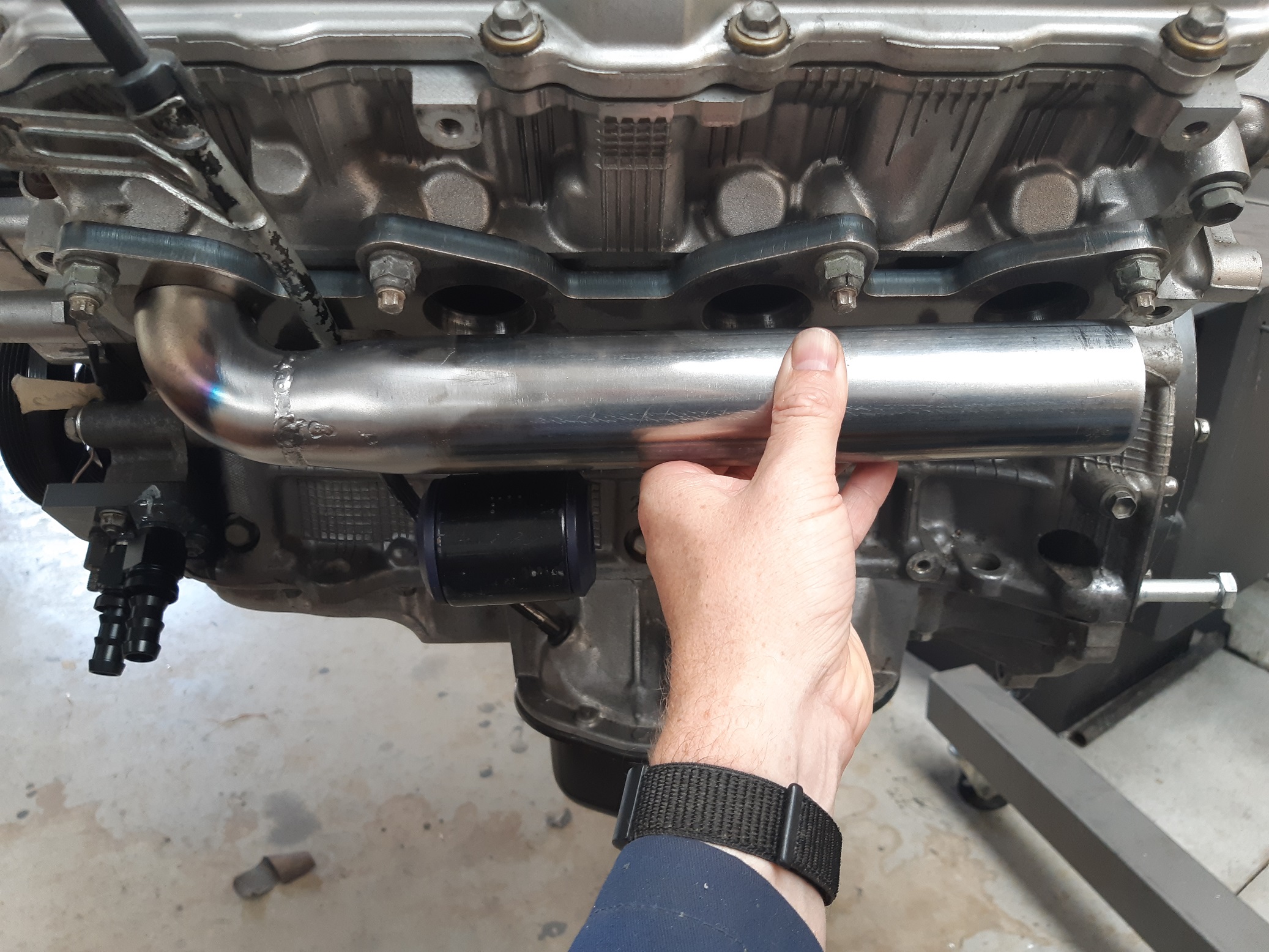
There it is on the engine. I may need to replace those straight fittings with 90's... I'll see when the engine is back in the hole.
-
Turns out they only needed to be angled a tiny bit. Trying to weld the bit in the middle is such a PITA, needs more tungsten stick out, but not enough gas coverage had to turn the amps up to 100 to get the puddle to start in the root of the gap. So shit was getting thermonuclear hot. There was some damage to the threads, but I cleaned them up with the tiny triangle file, and the sealing surface is still okay, so it will still seal. I had to mill some pockets for the nuts. And they both screw on. I did check that it still fits on the engine. Paint hasn't cured fully, I'll bolt it to the engine an a few days.
- 201 replies
-
- 15
-
-
Good idea. I managed to sort it another way.
-
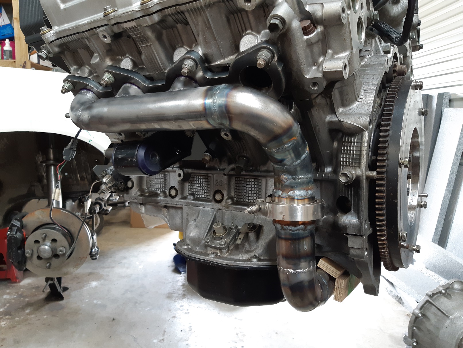
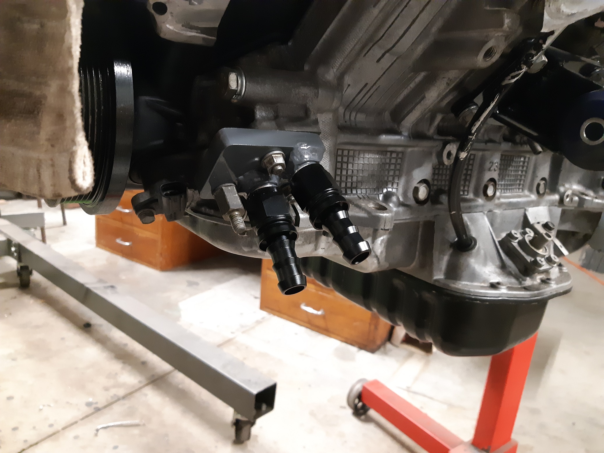
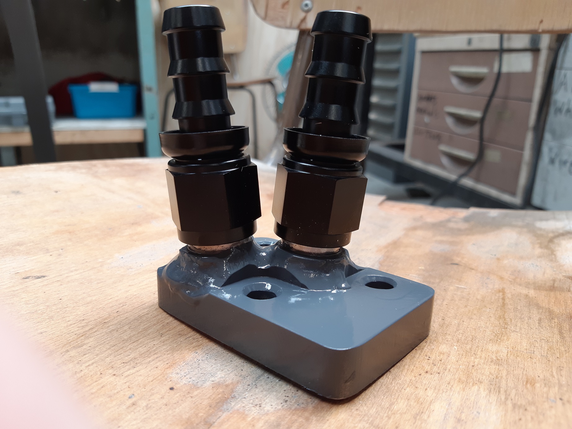
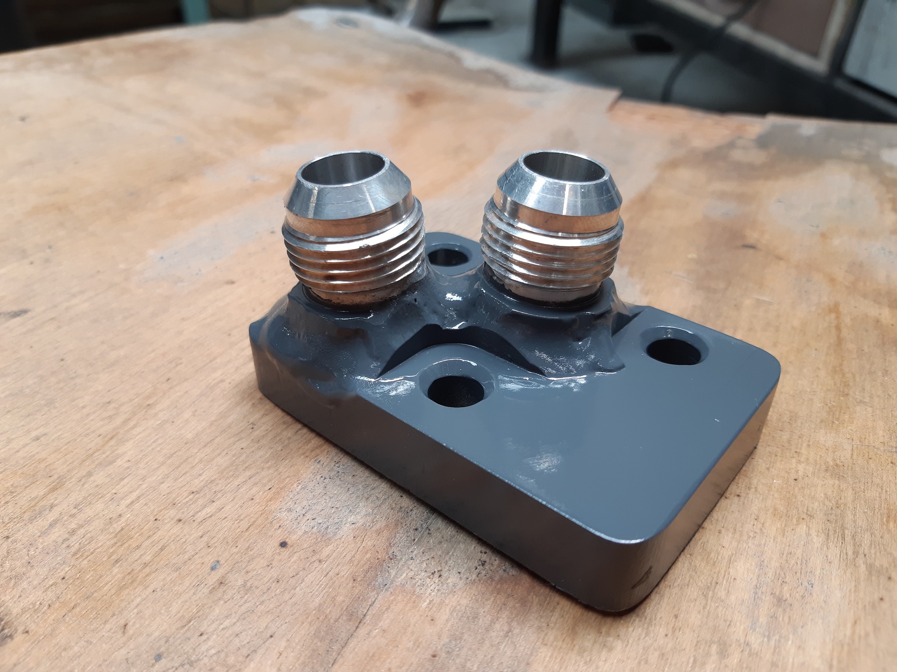
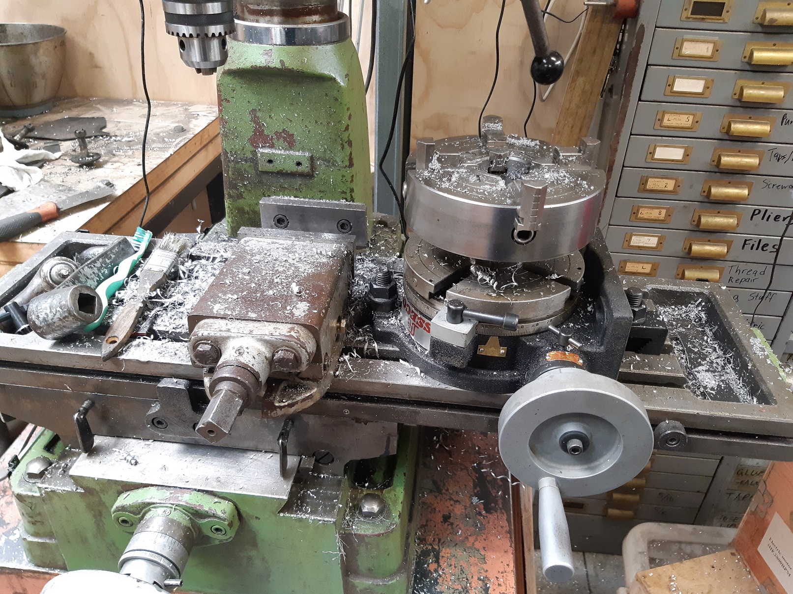
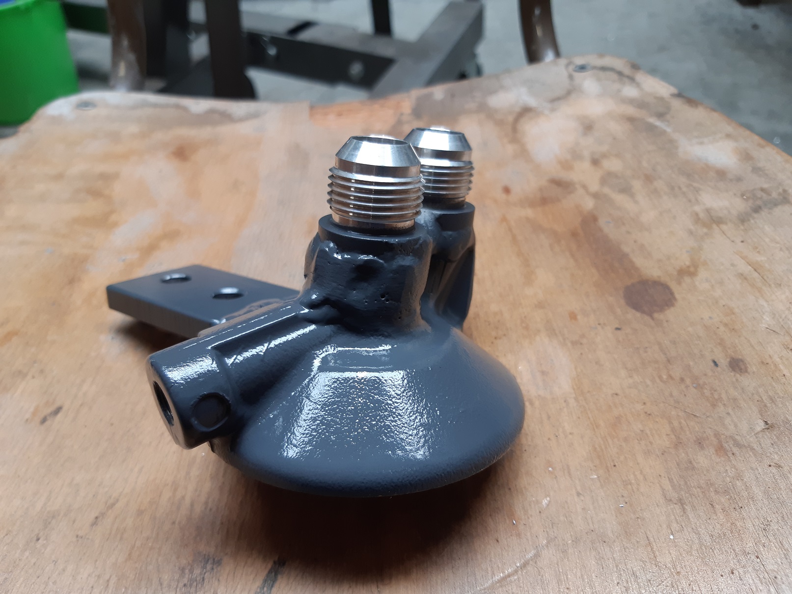
The original oil filter housing wants to be in the same space as the steering rack. So I decided to modify it and make it remote. This was my first attempt at aluminium welding, so it's a bit lumpy. It turned out okay. But I messed up drilling the engine side to straighten up the holes and cut into the sealing surface. So I had to make a new one. but it has a funny shaped figure 8 o'ring. So I had to break out the rotary table and use it for the first time. It turned out quite well. The holes are actually too close together for the AN fittings so I need to find some solution to that.
-
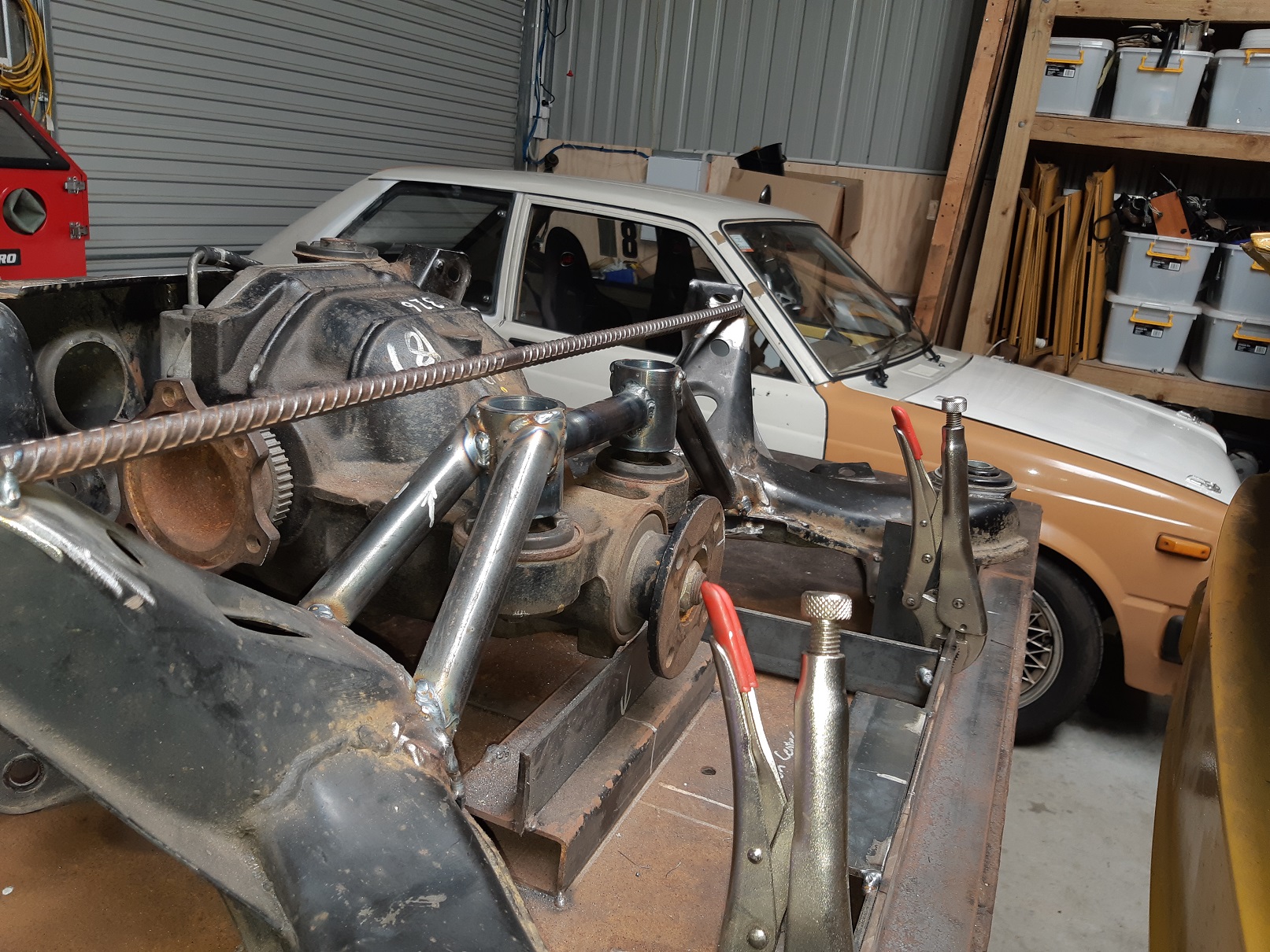
Posted in the discussion thread by mistake. Plasma cutter and carbide burr. Zip zap. It's in and diff is now self supporting. I still need to fill in the small square hole. And pull the diff out so I can finish welding the back.
- 201 replies
-
- 11
-
-
Yeh, I'll probably do that.
-
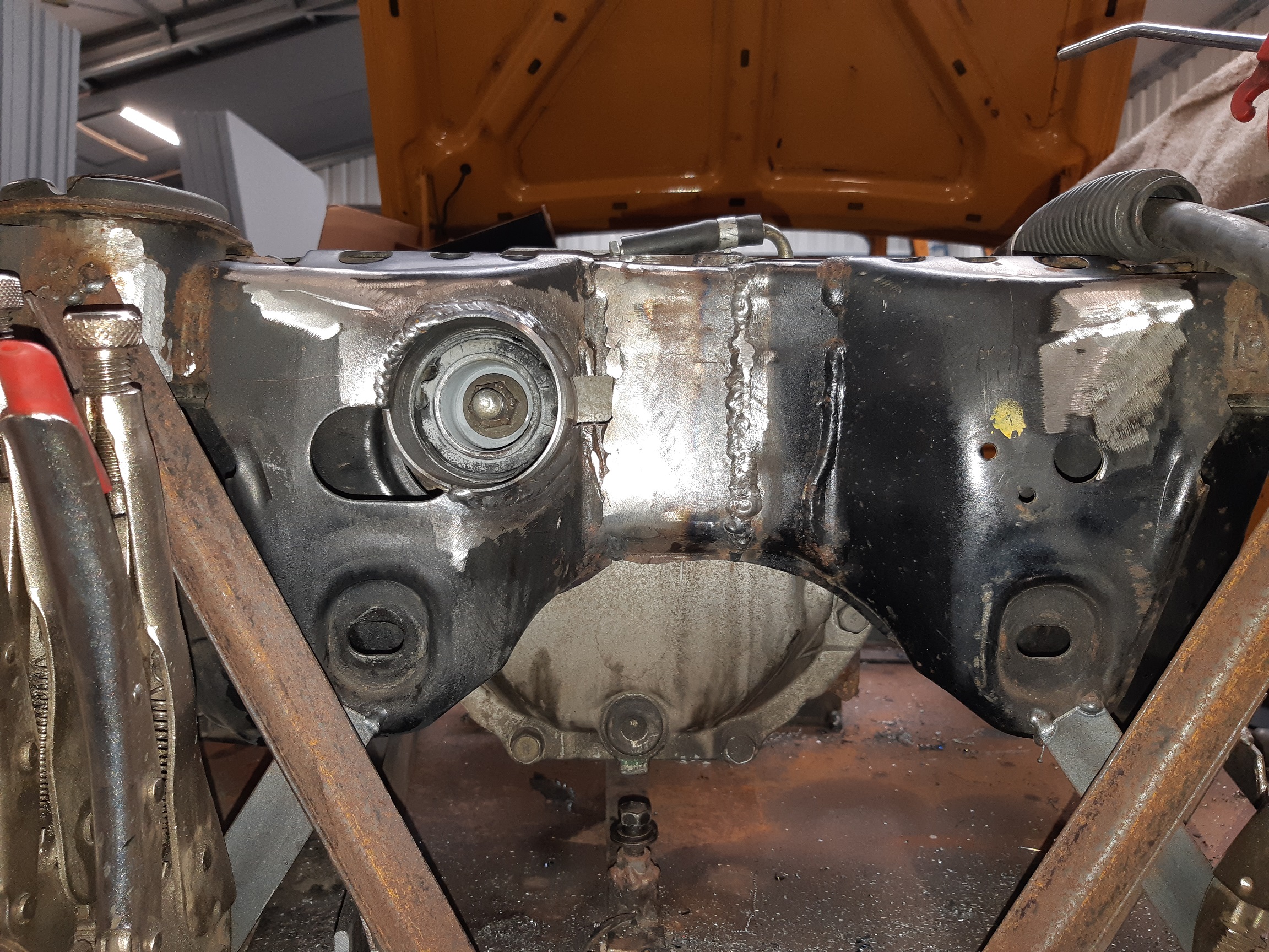
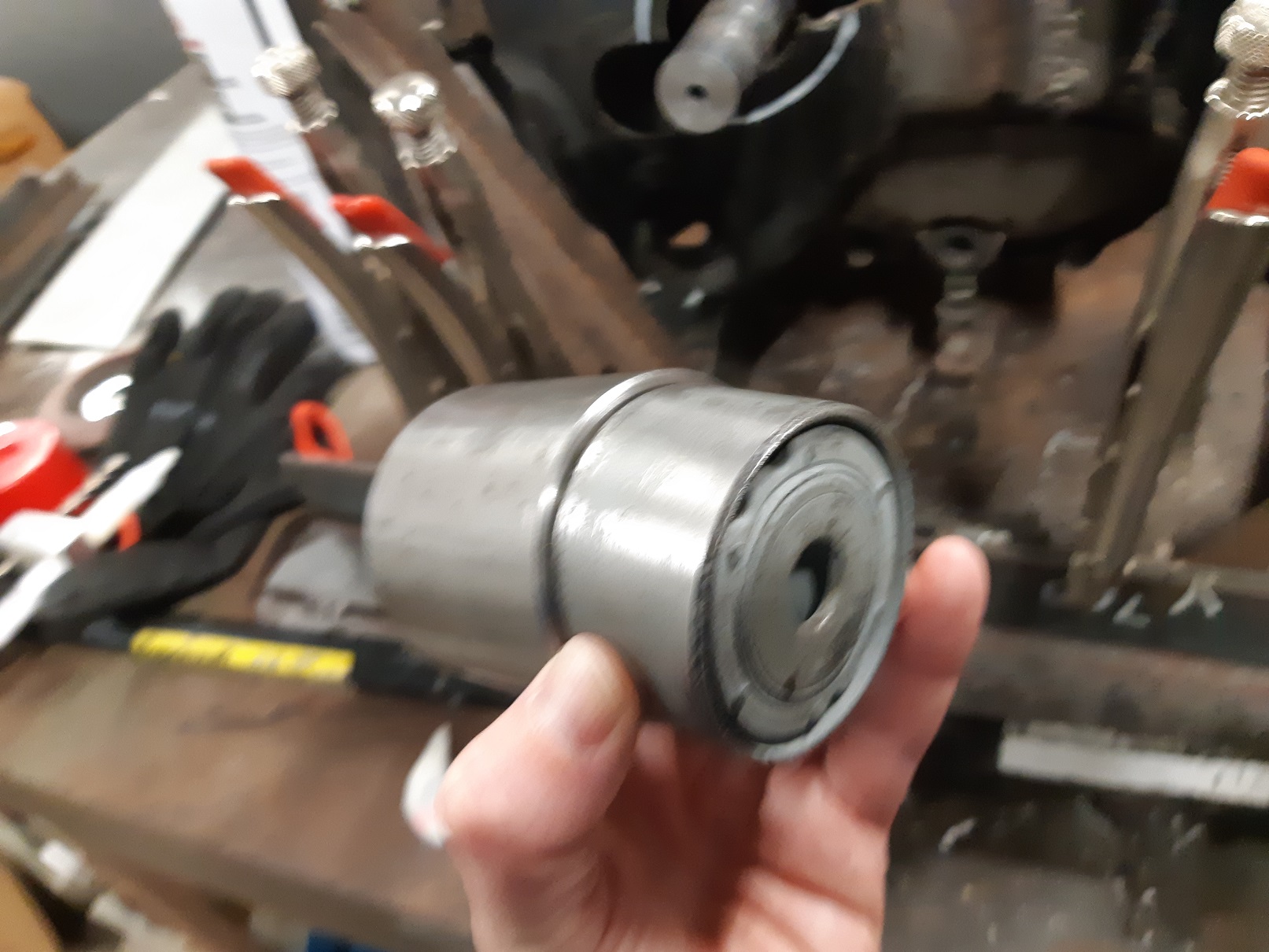
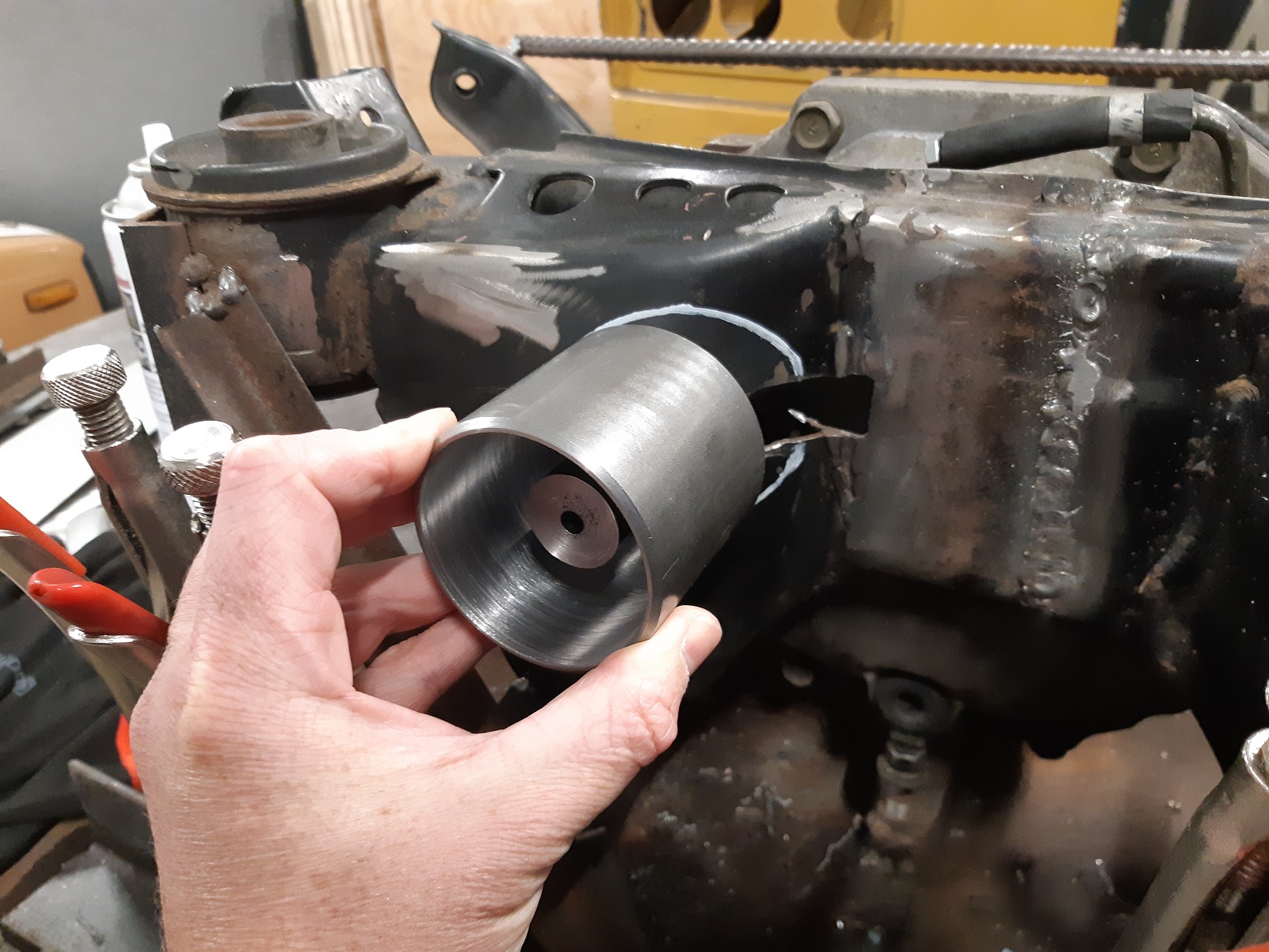
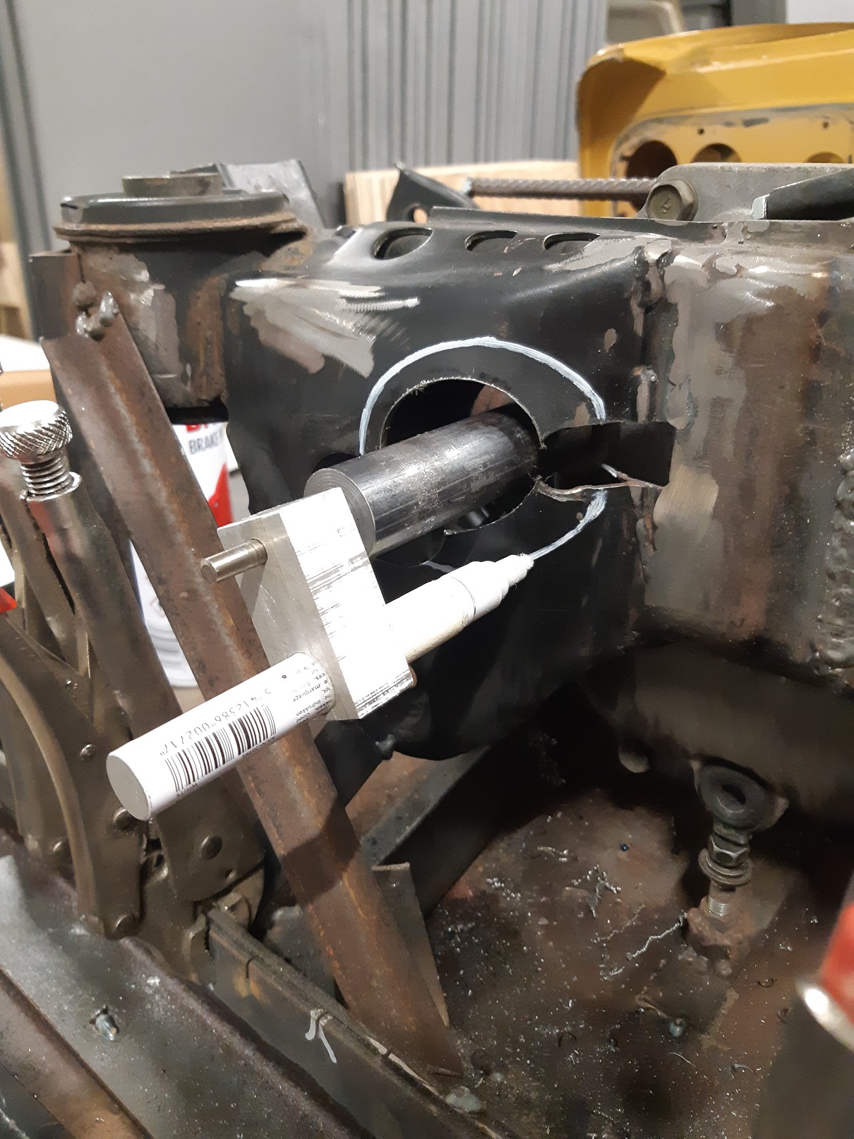
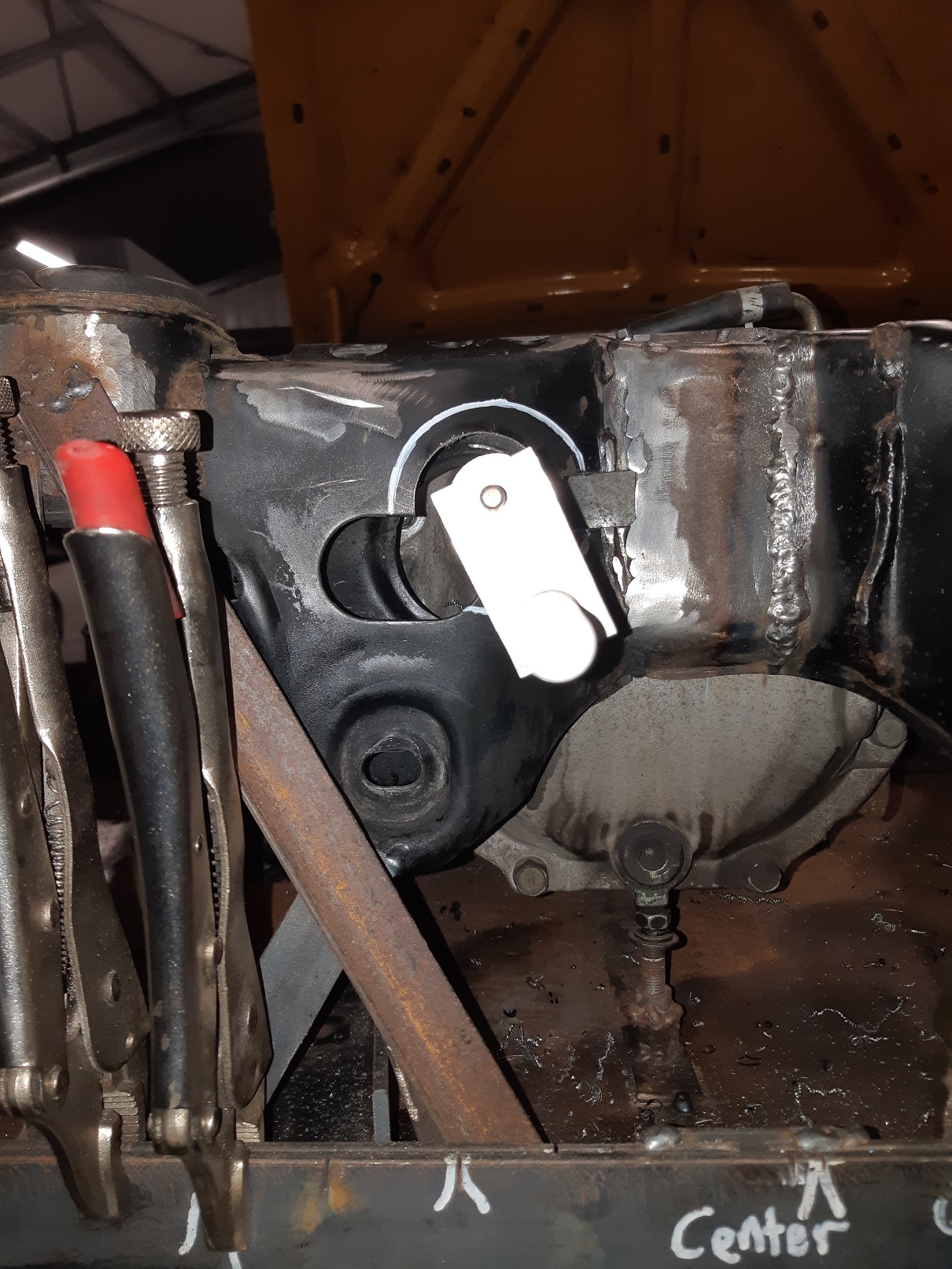
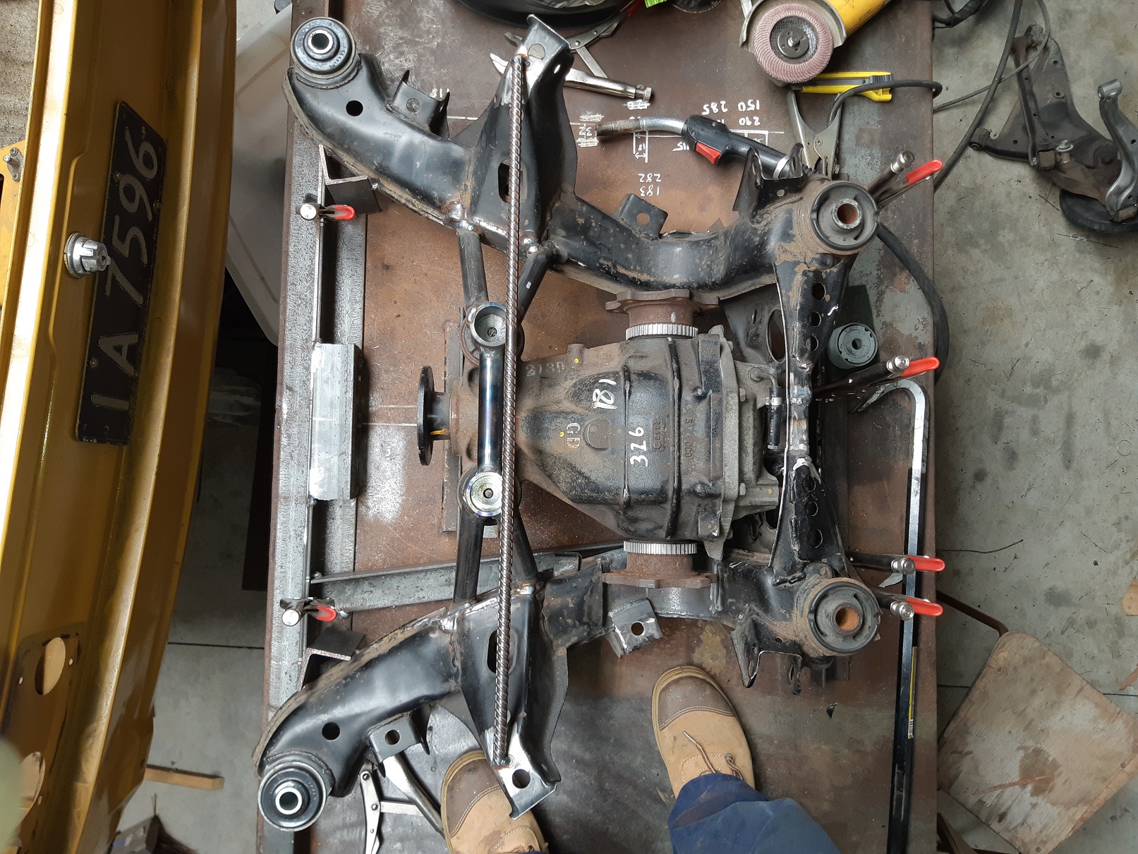
The rear mount for the diff is a stud that goes into a bush that presses into a sleeve. This required the making of round things with holes. And a rectangle with round holes. It's not this blurry in real life...sigh. So this bush presses into the sleeve. I need to weld the sleeve into the subframe. Initially I was going to guess and progressively hack until the hole seemed in the right place. But then I had a better idea. I drilled and tapped some round bar so I could screw it onto the stud to extend it. Then made this extremely complicated block to hold my pen so I could draw the hole. I haven't decided what I will cut the hole with yet. Angle grinder and power file probably. I did think of making the hole with a hole saw, but I don't have one the right size and trying to make something to guide it seemed way more complicated than this method. My next trick will be to weld the sleeve in without warping it and making it impossible to press the bush in. Maybe if I press the bush in first and use compressed air to cool the weld while only doing short runs.
- 201 replies
-
- 12
-
-
What a PITA to try get the pipe ends to fit properly. I'd get one end right, then the other end would be clocked wrong, or too short. I ended up using a too short pipe with one end that fitted correctly, then wrapped it in a thick paper sleeve which I could slide and twist and trim the end with a razor till the paper end fitted properly. Then I'd wrap the whole thing in another bit of paper to create a template to transfer to a fresh bit of pipe. It still took all day. Front of the diff is now supported by the cradle, not the jig. I've got to turn it over so I can finish the welds underneath. But it's too damn to hot be wearing overalls and a welding helmet in the shed now.
- 201 replies
-
- 15
-