


Roman
-
Posts
7,235 -
Joined
-
Last visited
-
Days Won
39
Content Type
Forums
Downloads
Events
Gallery
Posts posted by Roman
-
-
- Popular Post
- Popular Post
I havent really driven the car anymore, because I've had a clusterfuck of small inter-related issues which are causing things to not be fun.
So firstly the bank to bank imbalance was a pain - So I went back to setting up double e-throttle.
After a bunch of hours, and admittedly was very close to having it running good.
I decided it was quite un-fun to try make my own ethrottle controller, so I am using a borrowed G4+ Xtreme just as a 2nd throttle controller. Ha.
It's not doing anything except for actuating the throttle, and receiving throttle position target over canbus.
So once this was all going. I tried adjusting each bank individually to try get lambda to match bank to bank.
Still sucks, even when the motor is at steady state.
Still got some other issues somehow.
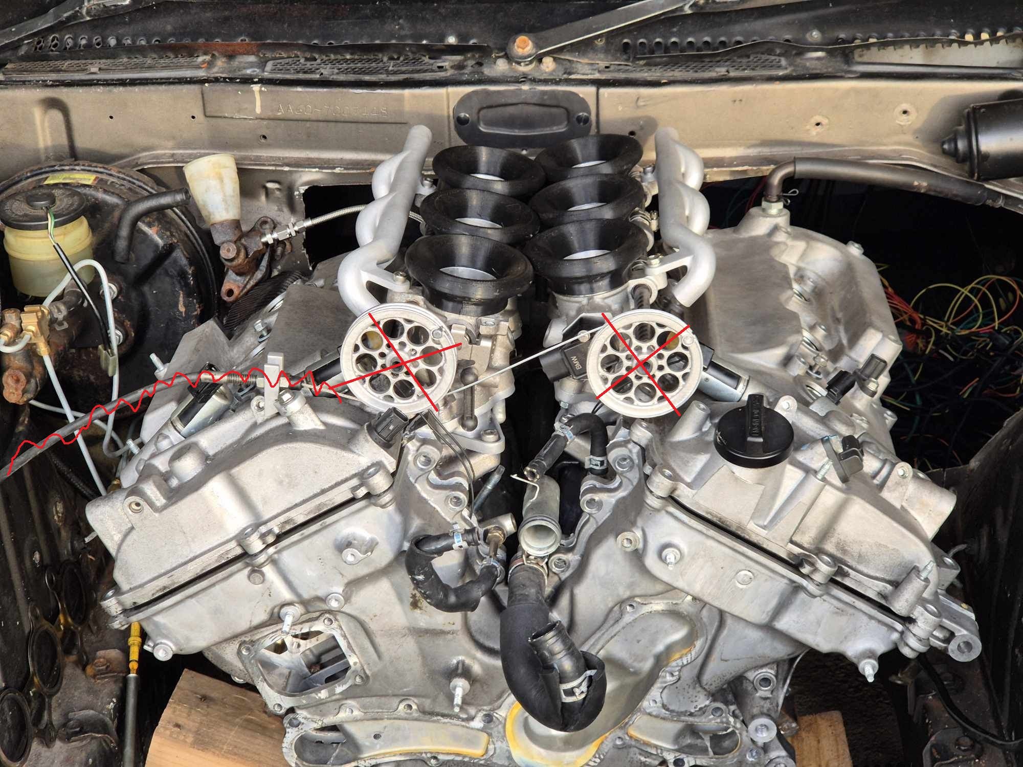
So I pulled the fuel rails off and printed a test rig to double check injector data.
Yep it was all good, no issues.
Sooooo what else could it be? Maybe individual throttle balancing.
Ages ago I tried to print a little throttle balancer thingy, but my printer was acting up.

But went back up the priority list.
It's a little tube that I can plonk on top of each throttle, and it'll give me an airflow reading through a MAF that I've stuffed in there.
Like so:
This worked GREAT!
My previous guesses with the screwdriver were massively wrong.
On one bank, all 3 throttles were being fed air by only 1, back through the balance tubes. The other 2 throttles werent flowing any air at all through the throttle plate.
It only took about 10 minutes to get everything balanced up, and now it's all matching a lot better, and idle is now really nice.
I've just printed a version 2.0 that has a smaller internal pipe size so it pushes the voltage readings a bit further up the scale, so its a bit more sensitive. It works well enough as is, but not making much use of the range available.
I will also add a capacitor to the output so it smooths the signal a bit.
My ethrottle pedal that was from the Echo, has a weird pivot point height and pedal height when fitted to Carina.
So it's quite awkward. But it's working at least.
However I think I will try adapt the sensor onto the normal pedal instead.
Hopefully now it'll start feeling like the car responds and acts a bit better when trying to dial in the fuel.Edit: some paddock tuning
-
 42
42
-
 2
2
-
Could wire the fuel pump to the oil pressure light being off and the "starter" position on the key.
-
2
-
-
True but we are trying to bully him into buying an ECU
-
 2
2
-
-
3 hours ago, mjrstar said:
In fact @Roman why do your videos not contain ecu data overlay?
I dont like looking at graphs
-
4
-
-
Bin it
-
1
-
1
-
-
@GARDRB Fuel pump control is simple, you just assign an output to turn on when rpm is over 100 (or whatever)
Assuming there isnt a specific function for it which does that. -
G4 cant upgrade to a G4+ or anything like that.
I'd recommend downloading PClink for both G4 and G4+ and see how they compare.
G4 software is alright but a bit more janky than G4+ which has had another 10 years of updates or whatever.
If you've got a serious itch for ethrottle, that's the only reason I'd consider the G4 xtreme over a G4+ storm.
(assuming G4 xtreme does ethrottle, cant remember)
-
-
1 hour ago, kpr said:
Generally to keep your tuner happy as possible. you want to leave your car at home, drop them off a large sum of cash, along with that V and pie, then leave.
-
3
-
-
45 minutes ago, bigfoot said:
You should, I bet you've got a lot of power hiding in your ignition table at the moment.
-
2 hours ago, shrike said:
What kind of plug do those sensors use? are they a deutsch plug?
Woops, didnt notice the plug on that one.
I use the ones that use an EV1 (injector) plug
https://vi.aliexpress.com/item/1005006120877474.html-
1
-
-
8 minutes ago, mjrstar said:
Is there hp left on the table by not accurately measuring iat on a stock ecu? My thoughts are being n/a then probably not..
If it's MAP based, then IAT decently contributes to the airmass calculation. But if it's MAF based then IAT does hardly anything.
Maybe you could wire in a potentiometer, so you can adjust it and see if you make any gains. haha-
1
-
-
If you get canbus based wideband controllers, you can run one in each bank and read from them both.
Then this way you also dont use up any of your precious analog inputs, annnndddd its way more accurate.
G4+ is pretty good but honestly wouldn't recommend going older than that.
As the software is a bit more janky and you'll grow into some of the features that are in G4+ but not earlier models.
Idle speed correction isnt a huge deal really, but yeah get rid of the stepper based one.
You can calibrate any sort of IAT to work, same goes for MAP etc.
However I've got a favorite that has good fast response and they cost nearly nothing. Dont go paying $100 for an IAT sensor, they are literally just a 0.005c thermistor with some plastic bits to hold it in the air stream.
-
2
-
-
3 hours ago, Rhyscar said:
and then I thought about it some more and a car is wider than it is tall, so the air moving around the sides has been displaced as much, if not more than that going over the bonnet.
Here's another thought.
You have a high pressure zone right at the nose of the car.
then a low pressure zone right at the middle of the rear of the car.
Why not run a big tube through the middle of the car, that joins the engine bay firewall to the lowest pressure area at back of the car.
Turn your car into a donut for reduced cross sectional area. Haha-
3
-
2
-
-
I guess another way to look at it - There are fast as fuck race cars, that do any and all of the above.
So long as you are following some well established general principals I'd not get too hung up on the details for starters.
I bet there's a fairly decent deadzone where you get similar results from lots of different ways of doing something.
Where different wings or angles etc are a fairly linear drag vs downforce tradeoff.
Then you're chasing incredibly diminishing gains to optimize it all.
Might be time for some sideskirts? 🤐-
1
-
-
Or if you can find an ecu for cheap, and an obd2 reader.
If you keep the MAF in the standard sized pipe the ecu's MAF scaling will tell you grams/sec airflow.
-
1
-
-
The Alfa 155 DTM cars did the dual radiator thing where they come out in front of the wheels. But yeah I agree its likely more to do with rules than ideal aero.
I am guessing much like BTCC, they werent allowed to change the body panels much or at all.
So werent allowed to chop a big hole in the bonnet, but modding the bumper was fine.
So it was probably just best way to deal with a bad situation handed to them by the rule book.
It's funny how many times race car stuff isnt "ideal" so much as, just best conforming to some really abstract constraints.
-
6
-
1
-
-
I just used Ali ones and they have been fine so far.
But I cant give commentary on if they stand the test of time or whatever.
However the crimp terminals have all been nice.-
1
-
-
I quite like the Sumitomo plugs, just google "Sumitomo 12 way connector" or whatever and heaps of things come up.
Have used these to make sub looms on mine.
-
3
-
-
- Popular Post
- Popular Post
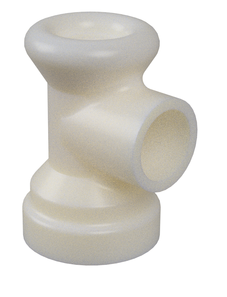
I havent had a chance to do much exhaust testing, apart from trying some gatling gun looking ends.
So this still has same cross sectional area as a single 3" pipe but it has longer pipe bits which protrude in, and has bellmouths on the entrances so it's hopefully not too restrictive.
Surprisingly, it does in fact sound a bit better even at idle.
God bless PLA and duct tape.
Changing the tips is not getting the sound I need/want (Didnt think it would be that simple, but best to rule out the easiest possibilities first)
I cant show some nerdy stuff about wavelengths etc because it was incredibly windy at the time.
Some ethrottle junk turned up in the post.
I gave it a test and it works great!
A single motor could pull open both banks, no problem.
So having 1 motor per bank and it should be super snappy.
I've got an ethrottle pedal from a Toyota Aqua wired in, and have the ECU running one bank through the onboard ethrottle.
For the second bank my dashboard now doubles as an ethrottle controller, and runs an H bridge to power the 2nd motor.
So a high priority CAN message gets sent at 200hz containing ethrottle target (throttle %) and actual throttle %.
Then it applies a PID routine to output a frequency to the H bridge to give it some juice.
It's all wired up and just needs PID settings locked in with some testing once it's operational.
Since I currently need to run ethrottle from the same microcontroller that does dash stuff.
I need to make sure I'm not hogging the processor for half a second (or whatever) with screen updates or something.
Currently my code has just been running in a loop, updating the screen every time it can after receiving some CAN data.
I never checked how quick this is, but its zillions fast.
I've now cut it down to a fixed refresh rate of 50hz for screen refresh, 200hz for ethrottle PID routine. Then the rest of the time it just sits there collecting CAN frames.
It's managing to catch 20+ lots of can frames in between each PID routine so there shouldnt be any issue getting the relevant ethrottle data from the ECU in time.
I've added some other bits and pieces to the code to make it easier to draw features, change color scheme and so on.
It's still not quite the aesthetic I want but it will do for now.
I've ordered a Teensy 4.1 (rather than my 4.0) as this has an onboard SD car slot. Meaning I can load gifs and bitmaps onto the SD card so it can display them on the screen.
Once that turns up I'll have the 4.0 as a dedicated ethrottle unit, and 4.1 just for the dash.
I've drawn up some new pulleys that can sit underneath the fuel rails without bonking into anything.
New one looks like this. No holes or anything, as I dont want to have any chance of snagging on something or jamming while it's further down in the guts of the intake setup.
So all of this stuff can go up on the wall of shame, and make way for an airbox.
Alsoooooo some Kelford cams turned up!
Exciting.
Big cams are the make or break for this project, so it's exciting to finally have them.
Am I completely full of shit about this motor revving out good? Lets see. Haha.
Lots to do at the moment but very busy.
The plan from here is to finish the ethrottle setup. Then get a decent full throttle fuel map / VVTI map sorted on the factory cams.
So I've got a good baseline for comparison.
Its incredibly annoying how much of the motor you need to take apart to swap cams.
If it was easier, I'd probably just do it straight away. Haha.-
30
-
Haha wow, thats some uncanny synchronization!
-
2
-
-
On 17/04/2025 at 18:59, Gravity Sucks said:
Wondering where you've got to with this project ?
What news do you have to share ?
I ended up moving house and not having any garage space any more.
There is an fb group for diy flow benches though, and using a MAF is a popular option.
Might get back to this one day, but not any time soon
-
1
-
-
Yeah the reason thats needed is because the FXE pistons have shallower cut outs, which is part of how they get the higher CR.
Hopefully the factory valve pockets on the 4GR are alright to get the cams setup on the factory timing marks.-
1
-
-
Might not be any point with my motor.
Since it's got a longer rod ratio than the 2GR, the piston dwells at TDC for longer.
So it would likely hit pistons sooner than a 2GR.
Maybe cant make use of the extra range anyway.
Will see.
Ordered big cams! Exciting-
7
-
2
-


Roman's 4GR V6 Carina discussion thread
in Project Discussion
Posted
Yeah it was just the easiest thing to test and rule out first.
But imagine doing it the other way, then doing that last and finding it's what made the difference. Would be gutted. haha.
Here's some ethrottle skids