Roman
-
Posts
7,233 -
Joined
-
Last visited
-
Days Won
39
Content Type
Forums
Downloads
Events
Gallery
Everything posted by Roman
-
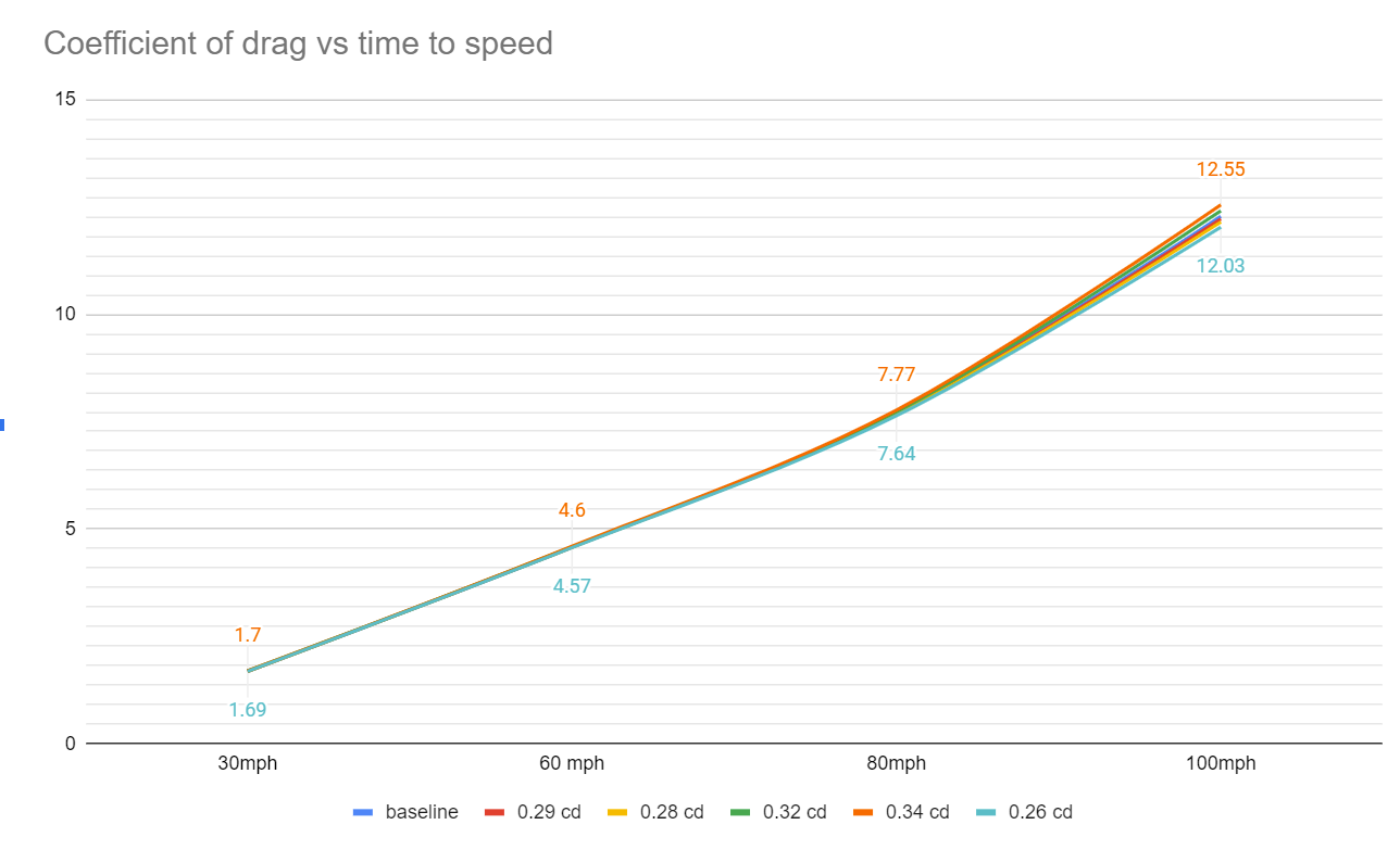
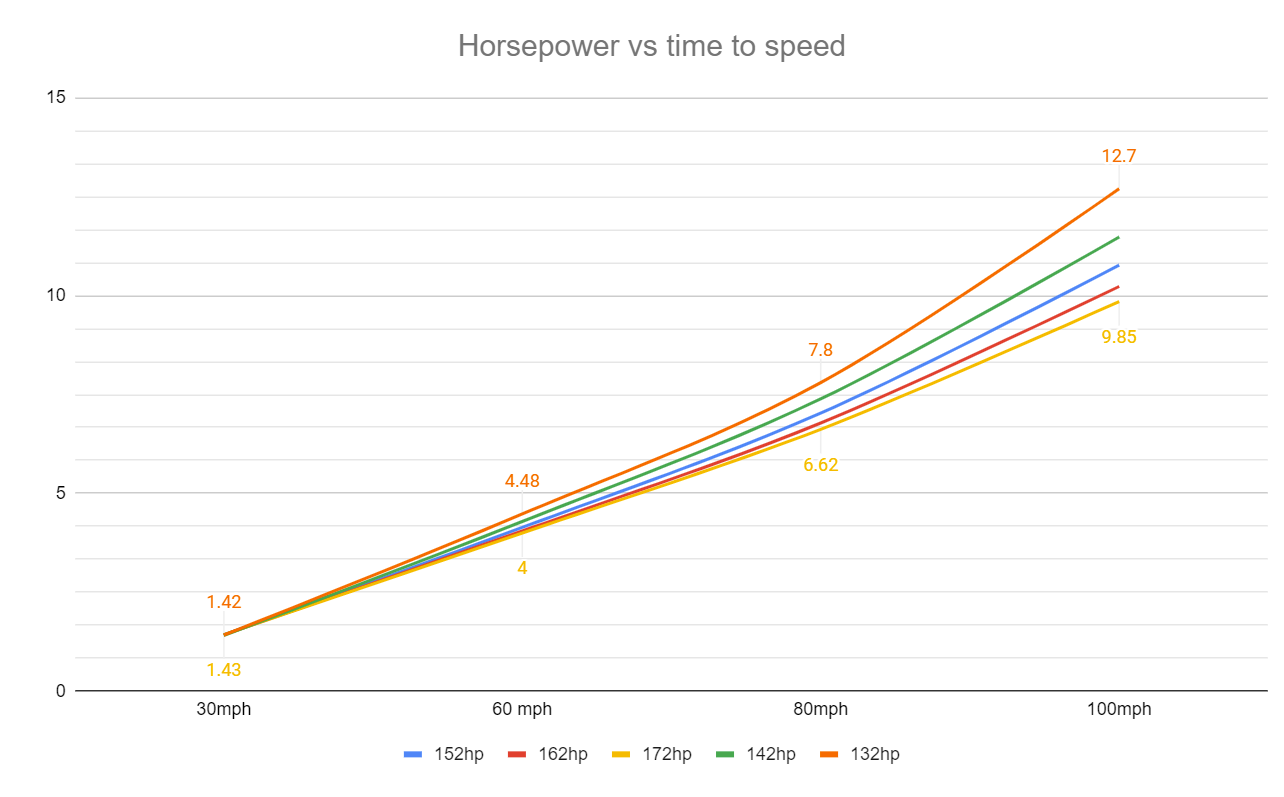
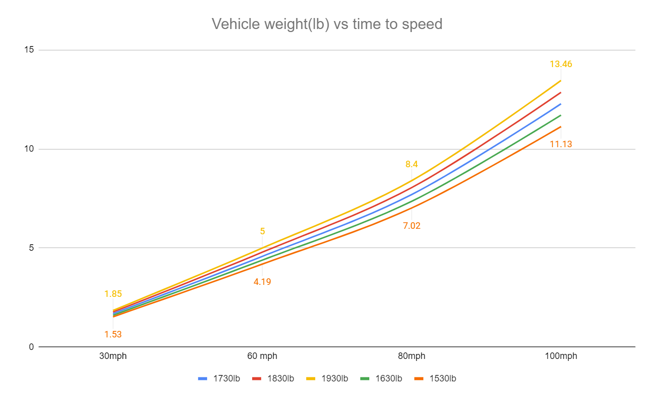
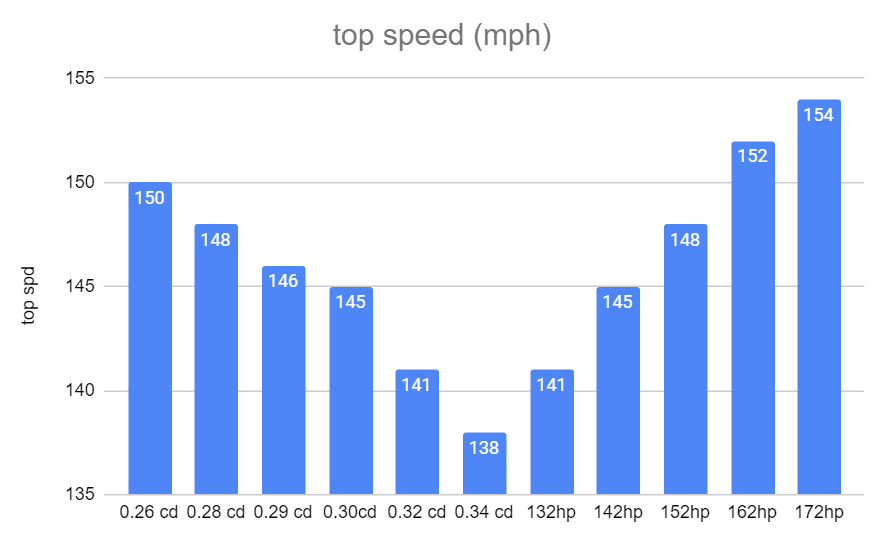
While finishing brackets for the wing, it's got me thinking about whether these changes are actually likely to help at all. In terms of reducing drag (There can be peripheral benefits to stability, reducing lift, blah blah) So then the question, what's better? Reducing drag by a bit, reducing weight by a bit, or increasing horsepower by a bit? As each of these things will potentially help at a different speed range for the car. Coefficient of drag means absolutely nothing for helping you get off the line, but at what speed does it matter? And so on. From day 1 I've had the echo setup in a program called Cartest which is friggen awesome for testing out combinations etc. It's especially great for just isolating one variable to see how things change. So, I ran some accelleration tests with the coefficient of drag adjusted in .1 increments, weight in 100lb increments, and 10 horsepower increments. Both up and down from a baseline figure. Collated all the info into some graphs, cos thats what I do. I added the numbers onto the graph for the worst and best result, just to give an indication of how much of a spread there is. For reasons I wont bore you with the horsepower graph isnt apples for apples with the other two, but you get the idea So it looks like overall, adding some horsepower is the winner, then reducing weight is second place, then reducing drag really is a low priority. Because reducing drag to 0.26 would be an absolute fucking miracle of science, yet it results in less top speed than simply gaining 10hp. Reducing drag is great for fuel economy, because if you can cut 10hp worth of drag down to 9hp of drag, and the car only needs 20hp to cruise along. Then you've made a sizable percentage of difference.

-
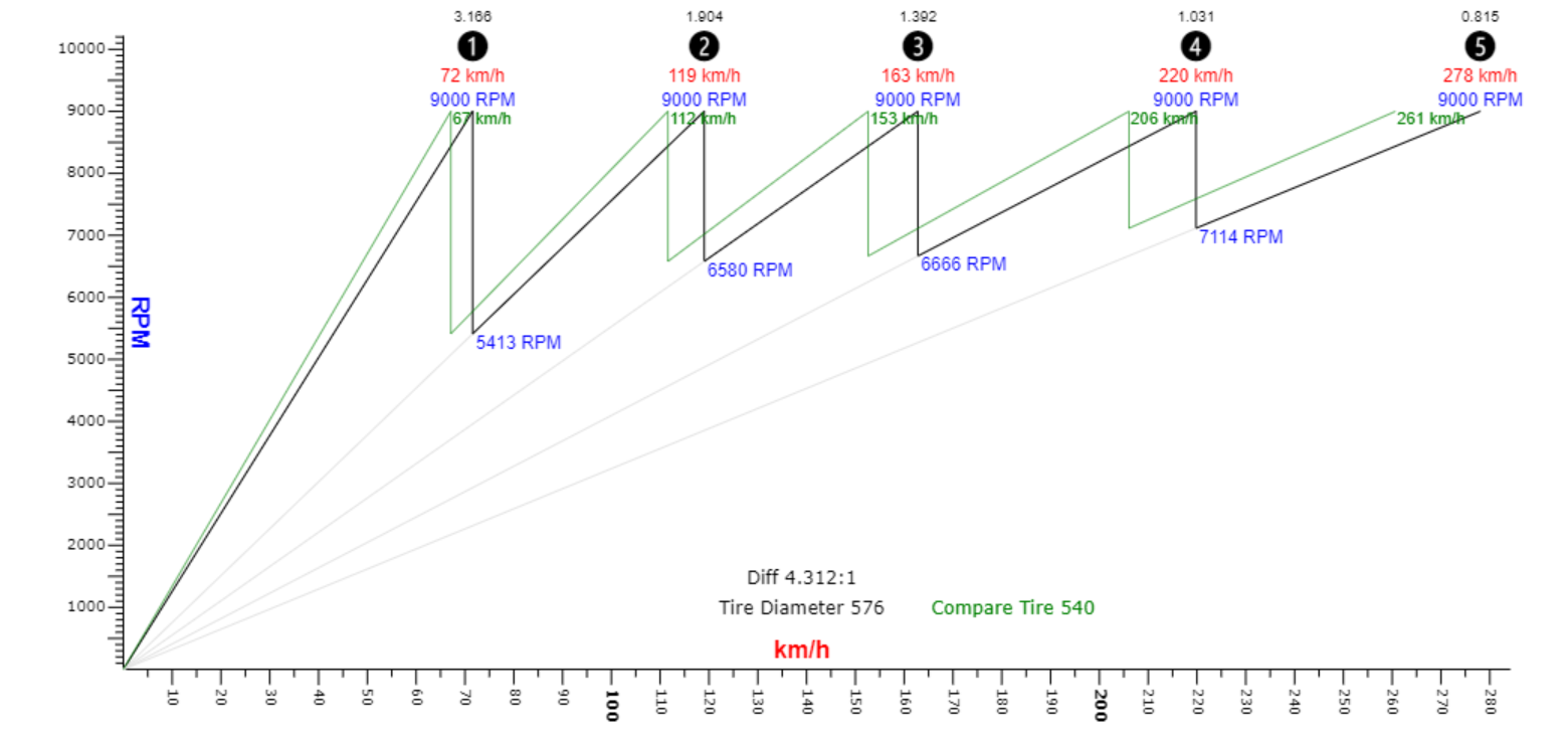
Yes it has, the change in tyre size means it's the equivalent of going from a 4.3 final drive to a 4.6 (compared to old tyres) Hopefully the stickier tyres will give it more of a slingshot onto the straight, and the shorter gearing might help a little with acceleration perhaps. However I'm nowhere near topping out max speed. At 9000rpm in 5th it was previously 278kph max, now 261kph max. I thought I'd have to shift into 5th but redoing the calculation says it will do 206kph at 9000rpm on new tyres. i think last time I was short shifting a fair bit by the end of the straight because it was feeling sluggy with the power drop from overheating. Black line is old tyres, green line is new
-
Weight difference for disc rear isnt too much. The main problem is it means i cant fit my skinny 13s on the back for drag day anymore. No brake fade at the moment, but i think currently the fronts have been doing all the work. To be honest it amazed me how good the braking was. But will have a bit more grip available now, so can hopefully lean on the brakes a bit harder. Im a bit nervous about changing too many things at once from last time, as it truly was amazingly good with such a simple setup.
-
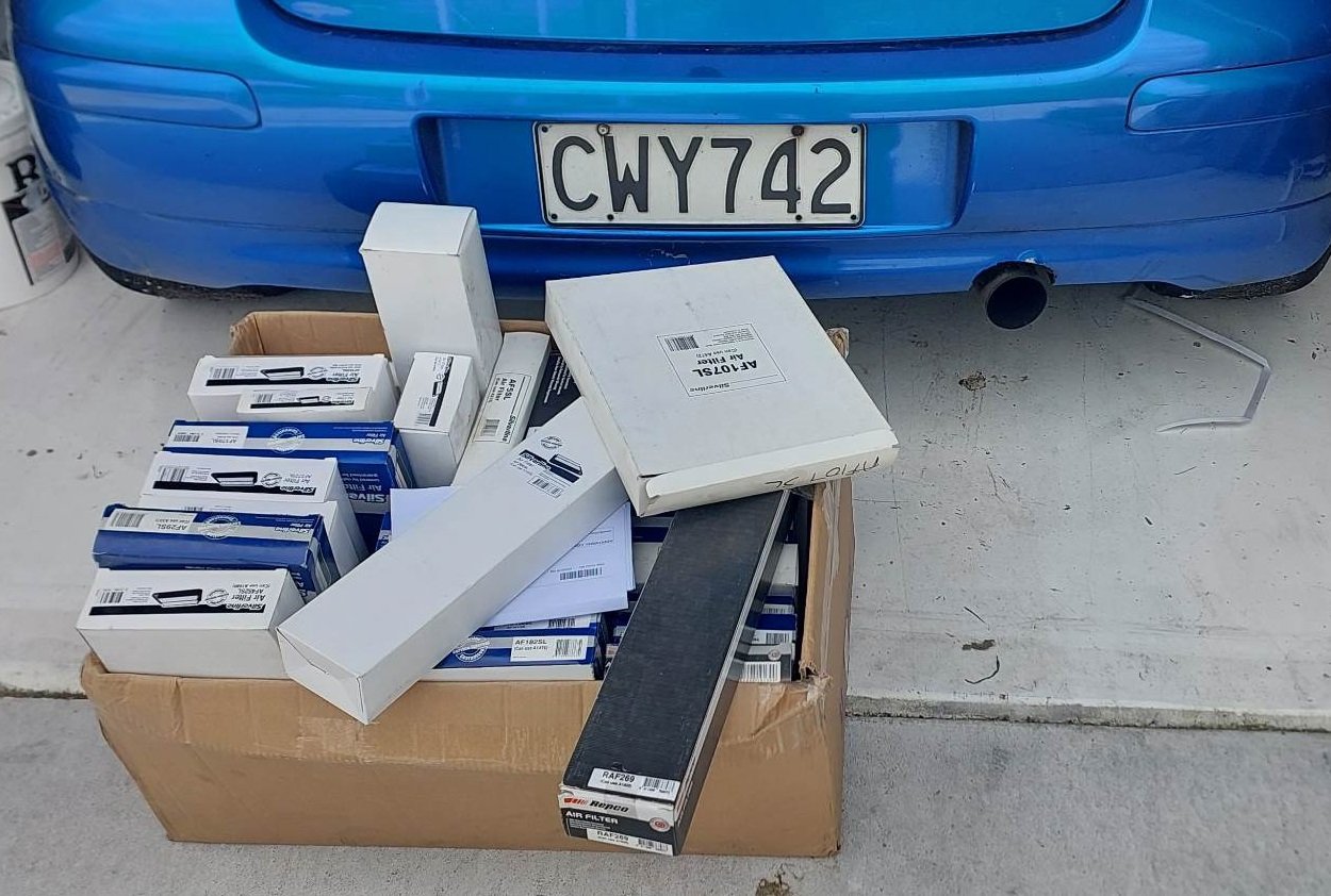
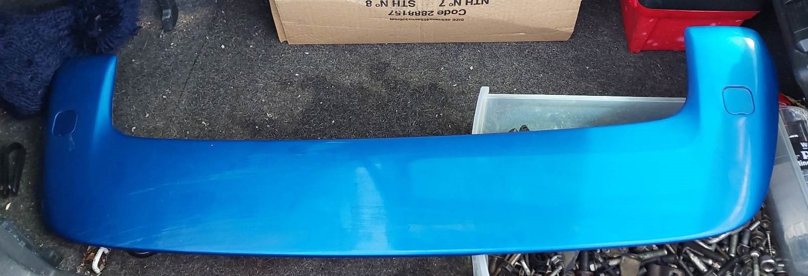
"Hi, I placed a punishing click and collect order" "Aahh, the air filters?" So will try figure something out, cant make the excuse of lack of options haha. Also, although I've enjoyed having this look like a standard car, I also want to try get a sweet top speed at Pukekohe this weekend. So I've fitted the Vitz RS sideskirts that I've been hoarding, and found a standard spoiler but thought it was a bit meh. So I robbed this, partially cos the colour was close enough Will take some fuckery to make it fit securely but its pretty sweet. Also, the tiny wheels/tyres are friggen sweet. haha I have found one problem since adding in max camber at the front though. I've got the camber bolts in the top holes of the hub/strut, this means when it adds camber it's pushing the top of the hub closer in towards the center of the car. So on full lock the CVs seem to have been binding. I switched the camber bolts to the bottom holes instead, and seems to be sweet now. I'm still procrastinating on fitting the disc rear setup, see how we go...
-
I know that this is a punishing request, But it would be interesting to see how good the fuel economy can be with your vvti able to go into prius mode! Would be cool to: Drive at 100kph and see what load/rpm you end up at. Go to this load/rpm on the dyno and see how much horsepower is needed for cruising. Then adjust the vvti / ignition timing / air fuel to see how little fuel you can use to acheive this much horsepower. Might be that you can dethrottle the shit out of it by retarding the cam by heaps, so make 30hp at 70% throttle or whatever Will really get some internet people mad if your car gets exceptionally good fuel economy as well, haha.
-
Higher octane usually helps if you are unable to keep advancing the ignition timing, because the engine is knocking or very close to knocking. However in this case the motor made its best power on dyno without knocking at all. So there's a bit of margin on 98 octane. In which case I dont think 100 octane would help. E85 might give some tiny tiny gains from charge cooling or whatever but it's unlikely to be worth the hassle.
-
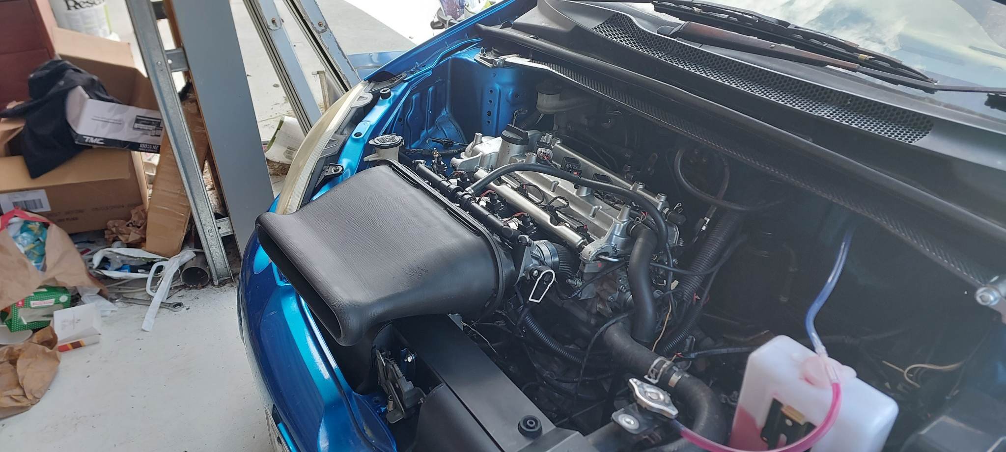
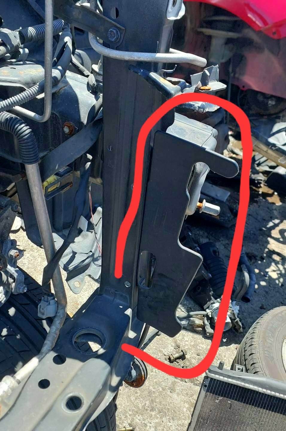
Got this all printed but as expected it's a bit silly. I dont want to drive the car with no bonnet, and I cant cut my spare one as this covers the bonnet latch. But physically seeing something there gives some inspiration anyway for how things might work. I think I'll switch back to putting the throttles closer to the head on the shorter manifold, so I've got more room for airbox activities. In aid of trying to find an air filter that will be appropriate, I've decided to brute force the problem. Some poor hungover person at Repco Morrinsville is going to really hate my click and collect order
-
Its more about hoping not to induce knock with the high compression / keeping a better safety margin and where I know its safe. So my ignition and fuel adjustments are very aggressively keeping things on the safe side if it gets hot. The motor got a lot louder and felt a bit flatter at end of the straights. Also since there's no oil cooler its more like the oil put heat into the block, then the coolant cools the block. So in a round about way keeping coolant lower keeps oil lower too. So far its been good at keeping the radiator temp to a decent level.
-
Okay sooo I just found a 2d CFD program that uses an MSpaint bitmap and a text file to set parameters Holy shit a brick I am going to absolutely pollute the internet with garbage now
-
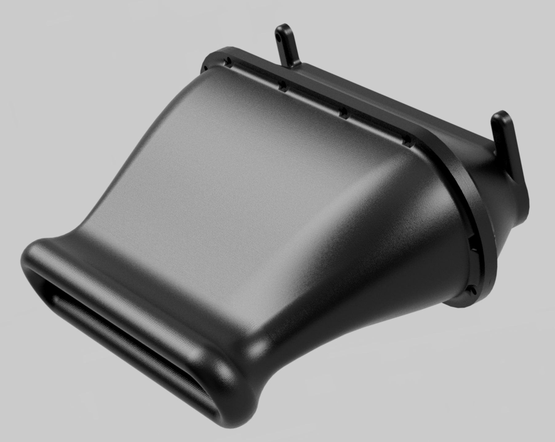
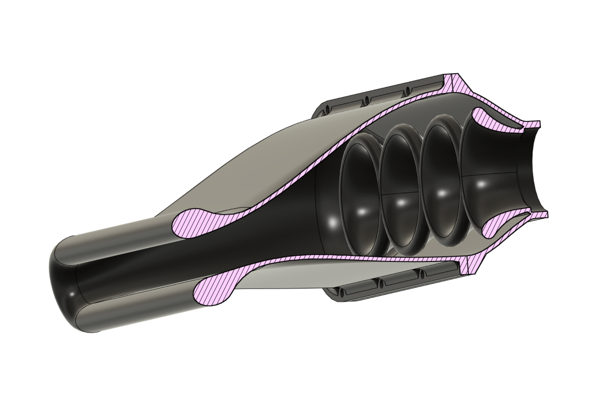
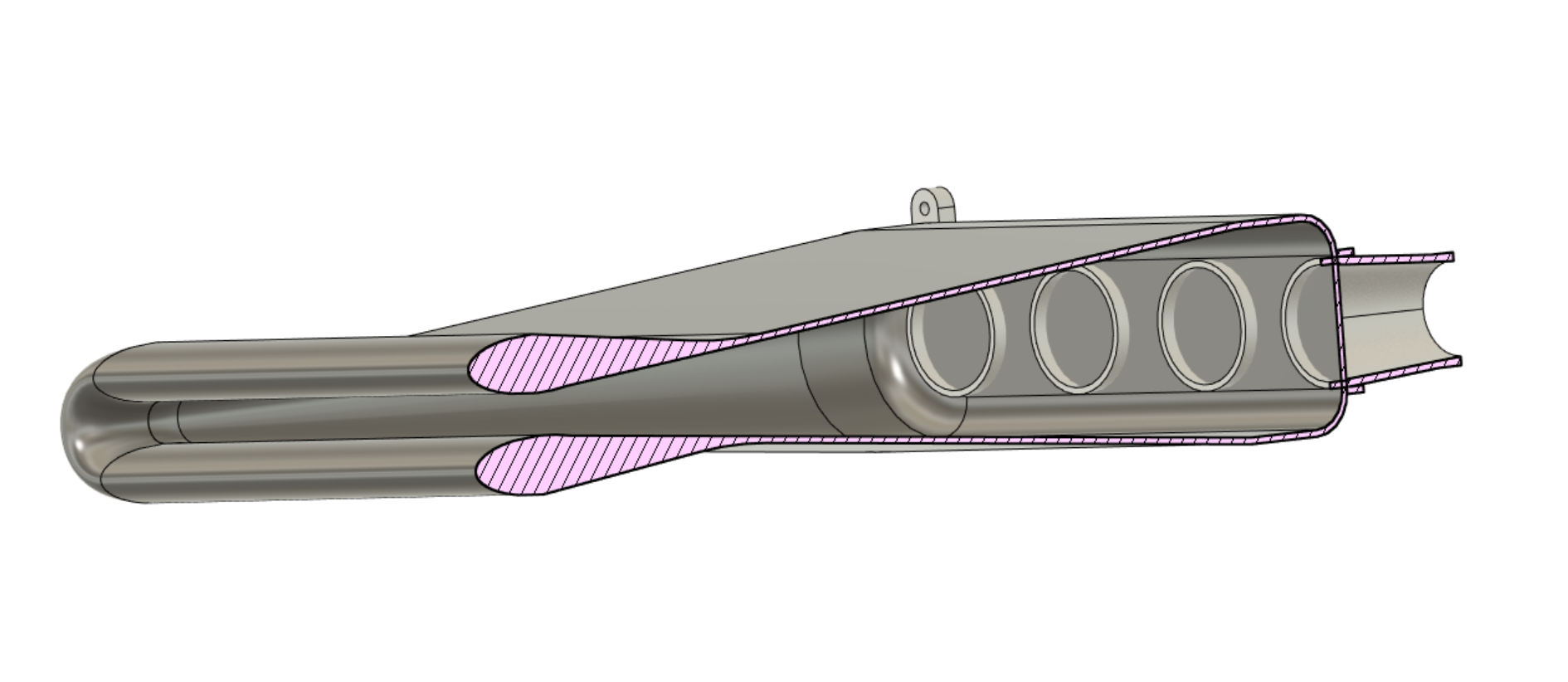
Started printing an airbox design. I decided that it's unlikely that I'll be happy testing just one iteration. So made it a bit more modular with 2 pieces so I can swap the fronts. Or run it without the front piece on at all for comparison. I had to add a 13 degree slope to make it parallel with airflow direction. I think the angle is a bit too steep on the diverging part here for this theory to work to its potential. People have said that 7 degrees is the magic number maximum for tapering out, but they havent mentioned whether thats in total or per wall. If it's 7 degrees total then 3.5 deg per wall is going to be difficult. I wish I still had a good CFD program. I've been trying to learn OpenFoam but man what a headache!
-
Every single OEM EWP implementation that I've seen runs a thermostat. Maintaining circulation and pressure are especially if an engine has water jackets very close to the exhaust ports or whatever. Can get localized boiling that then makes your measured engine temp do big see saws. Or just push all the coolant out of the overflow when it seems like nothing wrong. I've never seen an EWP setup that didnt have headaches from trying to run without a thermostat. Waterpump and thermostat do two very different jobs. So yeah it runs essentially the same way a mechanical pump engine does, except the pump speed is disassociated from engine speed. I can vary the pump speed using a PWM signal, but this was causing my pumps to blow up, as when I switch the car off I think the ECU was backfeeding voltage through the pump. If I reduce the pump speed the car could idle slightly lower from less alternator load but that was the only tangible benefit I found. I dont think there's such a thing as water flowing too fast to cool. If water travels twice as fast a in circuit it might only draw away half the heat each lap, but its doing two laps. But I think the issue is that a thermostat also acts to build pressure in the system even when its open, by being a partial restriction. So when you remove thermostat it doesnt get put under pressure.
-
Yeah it's running an electric pump, turned on full speed all the time. When the thermostat is out, it pushes water around like crazy. I dont think the pump itself is the issue, they use the same part number pump on the bigger hybrid motors too. Hmmm if it does fully open only by 95 deg then maybe it's not so bad, as it only got to 96. Will need to drive it for longer to see if that number keeps going up, so long as it's not over 100 then it's probably fine.
-
Here's an interesting one
-
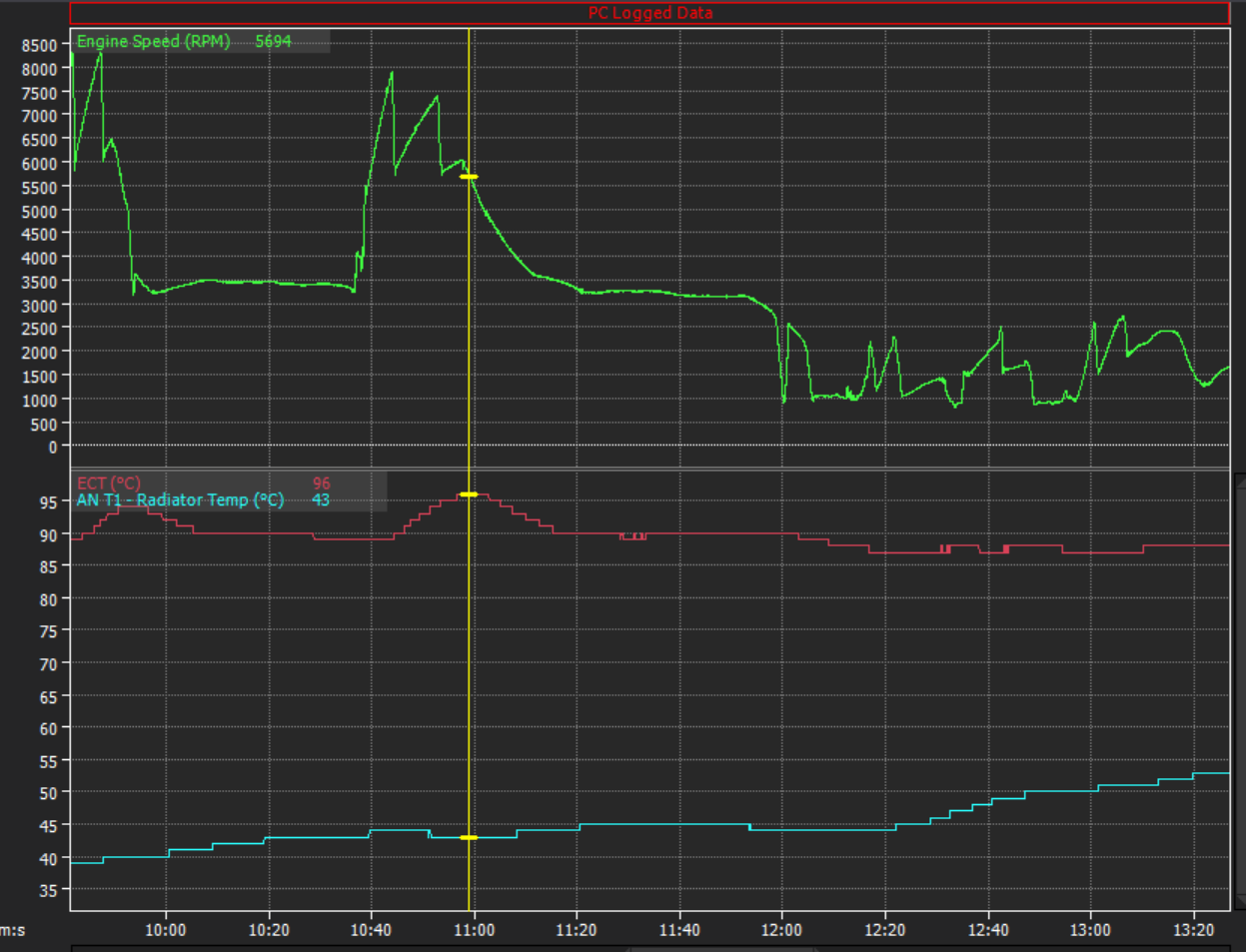
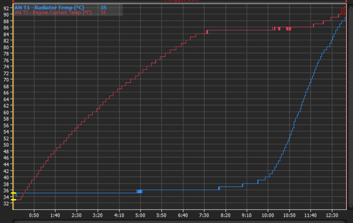
I went for a drive with the new radiator setup. I dont have the radiator fully blanked off, but generally the radiator stays around 35-45 degrees when cruising at 100kph with no fan going. So doing some full throttle stuff, the engine temp still spiked even though radiator temp stays low. So that's interesting. Maybe the flow through the thermostat is the current bottleneck. After all its designed for 75hp maximum and tootling around at half that. I guess I can try take the thermostat out and see how it compares. The radiator temp did slowly creep up some time after a full throttle run, so ti will be a bit more punished with continous full throttle at a track day. But that's where finishing off the ducting will help.
-
Alright so rather than trying to make this fit in a cramped space and get a compromised result. I'm gonna start with what I figure the ideal ram-air box would look like and I'll cut my spare bonnet around it. Then see what difference there is in a best case scenario. Will hook up a map sensor into the base of the airbox to see what sort of pressure gains are possible. Then if it works good, I'll try compare that best-case result to something that fits the car. So will have a base plate section that is 100mm radius around the throttles, and then 60mm long non tapered section (so this is high pressure zone) Then from here it's extruded with a 5 degree taper (may as well stay safely below maximum) Then a bellmouth on the entrance to try make sure flow stays attached. This thing will be absolutely monstrous, haha. About 525mm long so I cant print it all as one piece. However if I make the angle 6 degrees or 7 degrees then maybe it will be fine. The narrowest part of the slot has an area equivilent to an 80mm circle which is heaps. Could maybe go a little smaller. However I've also just assumed that the airflow direction will be perpendicular to the throttles which it wont be. Will go measure what sort of angle there is. then adjust it.
-
Alright consider me sold on the subject! Will be something interesting to test. Especially since I've got your differential pressure gauge to test things with. Then I can hook up a MAP sensor into the airbox as well. However I'll need to try figure out what is actually going to be physically possible to acheive. Maybe I will use my other bonnet before I cut it for other reasons, and make a little airbox inlet space.
-

Discuss here about Yoeddynz's little Imp project...
Roman replied to yoeddynz's topic in Project Discussion
Agree, looks bloody awesome! -
It could possibly be weight neutral? or fairly minimal... As my fan assembly is a lot lighter than standard. Shame on me for not weighing everything already though. haha. I remember reading something from a BTCC guy who said they looked into ram air type setups and said there was no point. As in ideal conditions its only a millibar or two of extra pressure, at maximum speed. Then you lose that as soon as you are following someone else. But then some of the bike manufacturers gloat about their ram air setups so who knows. I've still got a 5kpa differential pressure gauge on loan from @Hyperblade so I guess I can go do some tests at some point. But likely limited by space anyway. The main issue is that I would like to incorporate an air filter arrangement, which makes life a lot trickier than the cross section implies. Still not sure how this will work which is why I'm just working on the front bit for now instead.
-
Speed based fan thing is a bodge for not knowing radiator temp. If going 60kph keeps the radiator temp down, then theres no need to turn it on anyway. Im not using any shroud, ive got a single 12" fan mounted as close to the top radiator pipe as possible. As this has the highest temp differential of the whole circuit so cools the best. Fan shrouds improve fan efficiency but block flow at speed so wont be using one. As its only at trackdays that cooling is an issue.
-
If i could only have one engine temp sensor. Then what you describe is the best place. Or more specifically somewhere inside the circuit of flowing engine coolant when the thermostat is closed. But measuring the radiator gives an indication of how much cooling capacity is in reserve. Older cars used to have a thermo switch in the bottom of the radiator to trigger fans. Newer cars seem to skip this and just have the ecu trigger from engine temp. Likely to save costs.
-
Also I fitted a radiator temp sensor. I lett the engine warm up with the radiator fan turned off to see what happens. It behaves how you'd expect. The engine gets to temp quickly, radiator stays cool, then eventually the radiator saturates with heat too. The reason that this is interesting is that currently the engine fan comes on only based on engine temperature. So in order for the engine fan to come on, the entire circuit has to saturate with heat past the point where engine temp is stable. Having a radiator temperature input means that as soon as the radiator water starts on its curve upwards. You can anticipate the system saturating and turn the fan ahead of time. The car's not mobile currently but I think it will be interesting to see what sort of temps the radiator stays at in various conditions/speeds. It will probably be a reasonably good indicator of how well any ducting etc is working too. Something you wouldnt be able to see from looking at just engine temp. I've still got a few weeks up my sleeve until trackday but feels like there's a lot to do before then. I should really get around to fitting the disc brake rear as well.
-
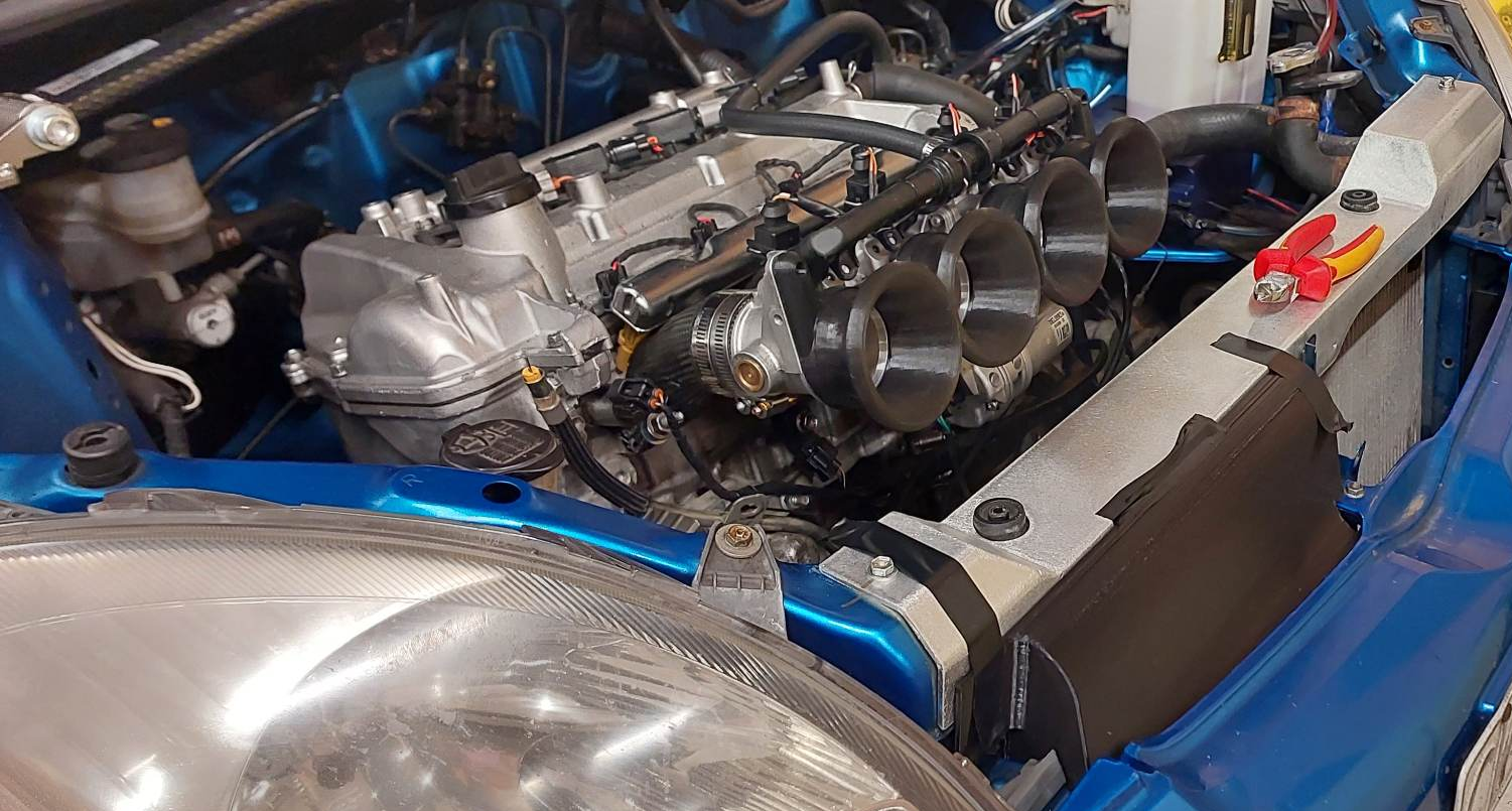
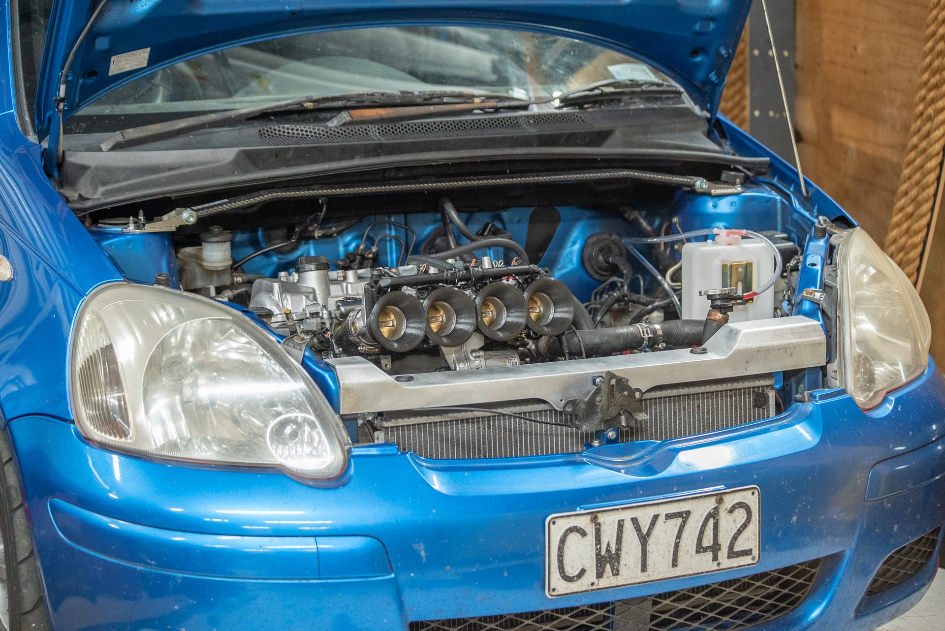
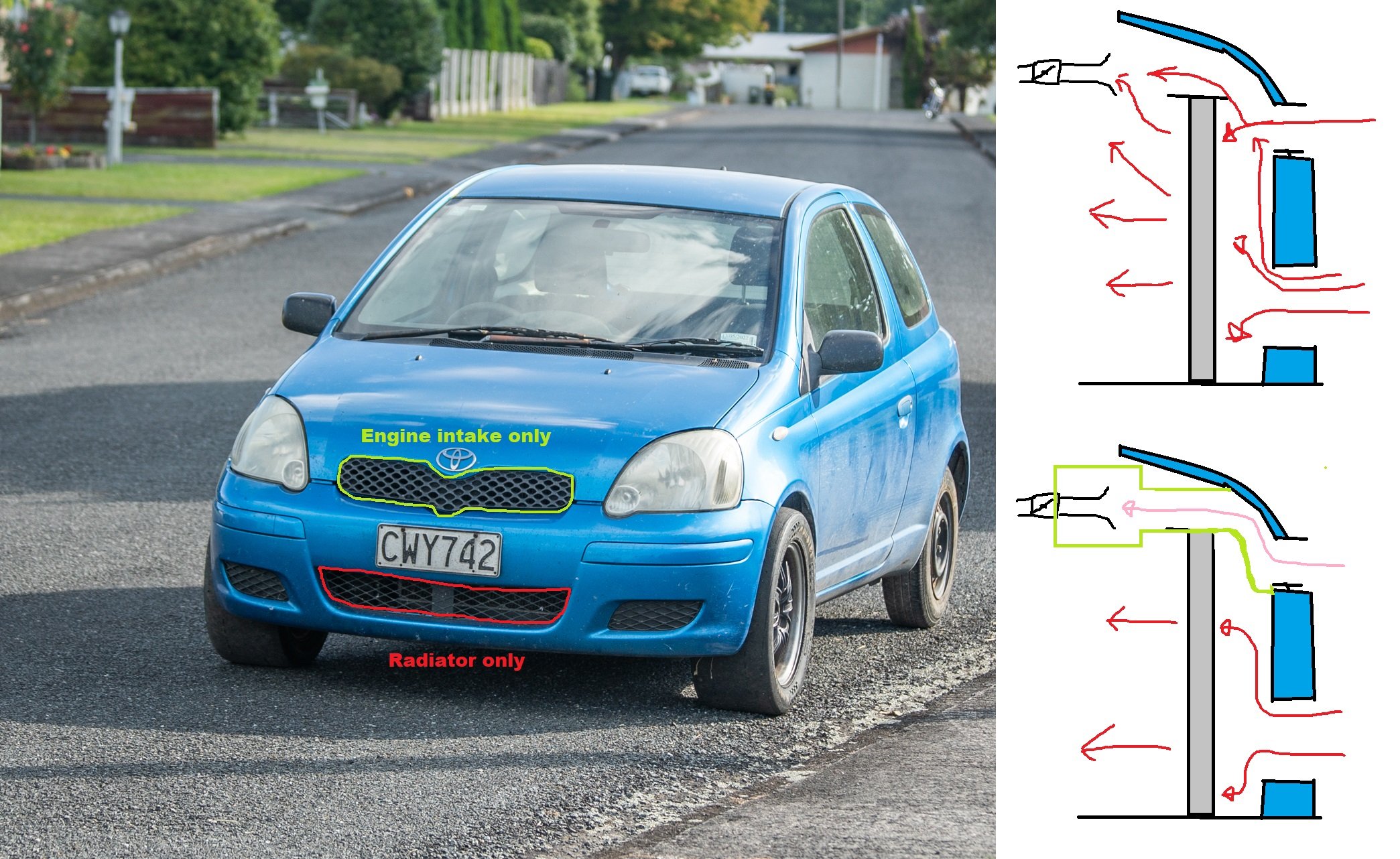
Got this sorted, and it's awesome. Thanks again Stu! The extra room gained is incredible. So the next thing to decide is how a filter or airbox or whatever is actually going to work. On the engine bay side I've been tossing up some ideas but not 100% sure yet. However ahead of the radiator and crossmember, I think it's going to be best to completely divide the engine air and radiator air intakes. Looking at the front grill area, there's a decent cross sectional area available through the holes in standard grill. More than enough to feed the motor. So sketching it up / cardboarding it up, hopefulling something like this works Printed out a test piece for one side and fitment is nearly there. Should be good!
-
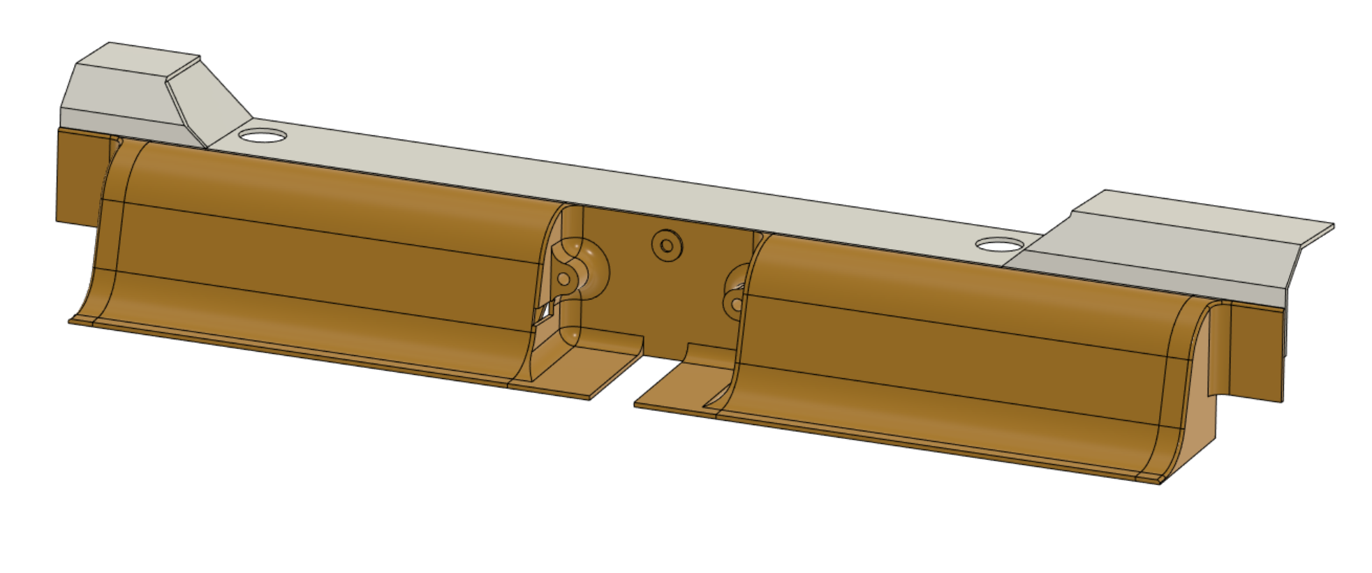
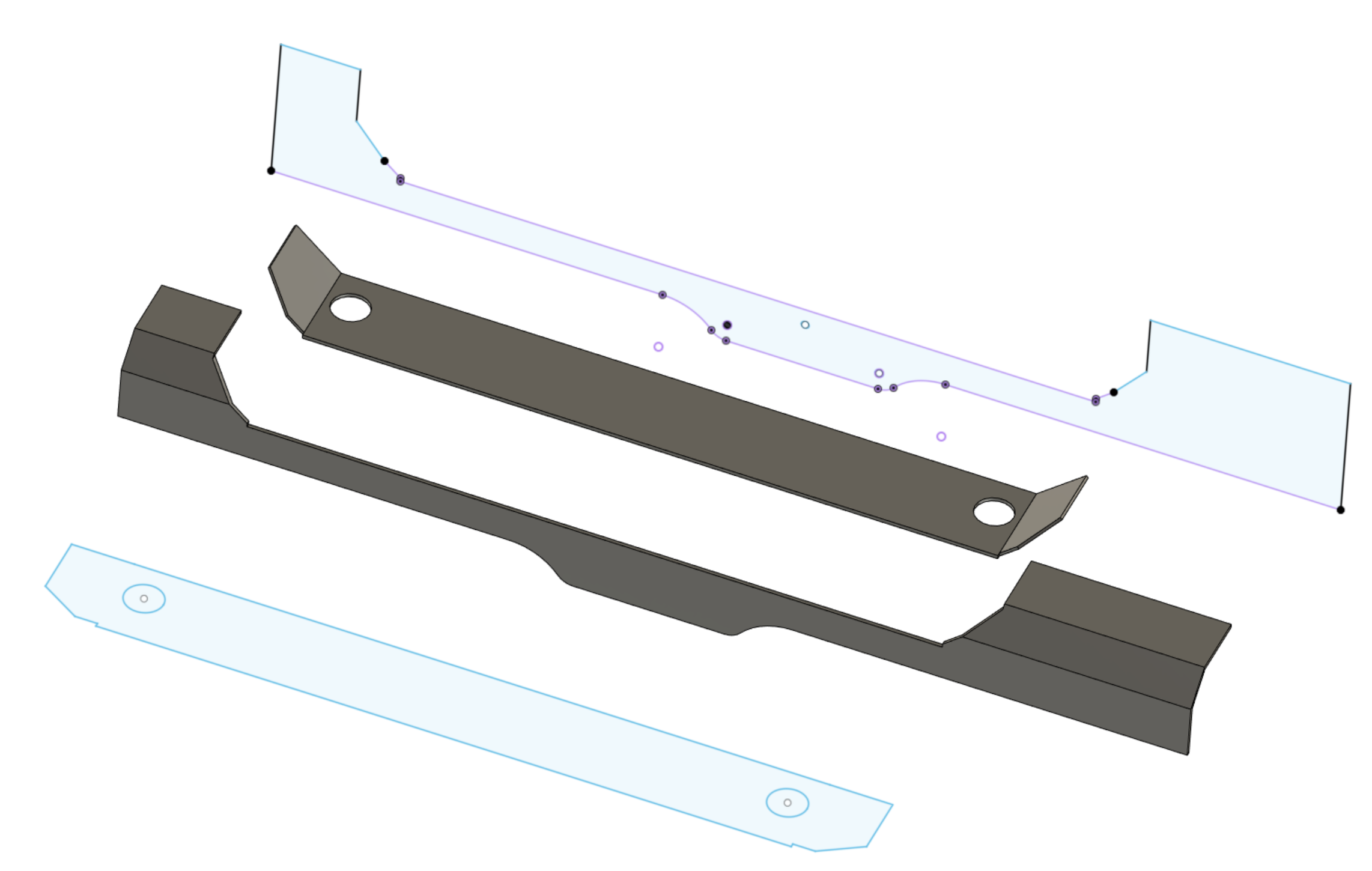
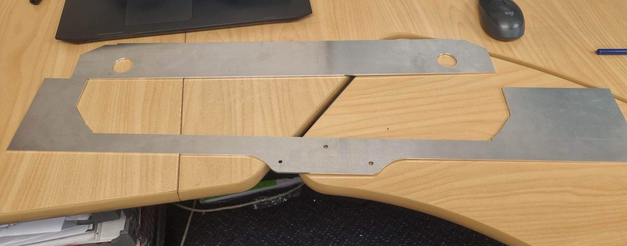
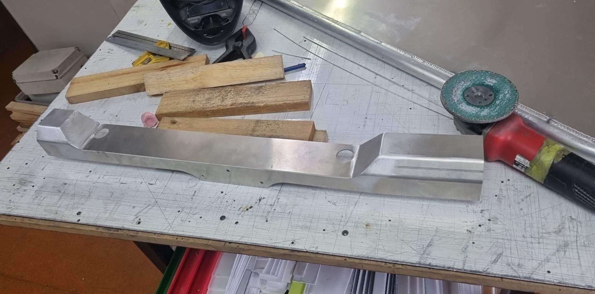
I was planning to do usual trick of print and then smoosh carbon on it, however OSGC @Stu offered to help making one from aluminium. So I revised the drawing to be more suitable for this method and sent him some DXF files for cutting and bending. It looks amazing! Cant wait to fit it up. Love your work Stu, thanks heaps! Then the next fun part will be making the top feed airbox that runs over that new gap. Having an extra 35mm near the throttles is an absolute life saver! Also I paid up for a Pukekohe trackday on the 14th January. So I'll need to have the radiator and 13" slicks setup all finished by then. Will try get an airbox finished as well. Cant wait to see how the slicks go, and the double whammy of a little more power from the engine (hopefully) not overheating and also having a better cold air supply.
-
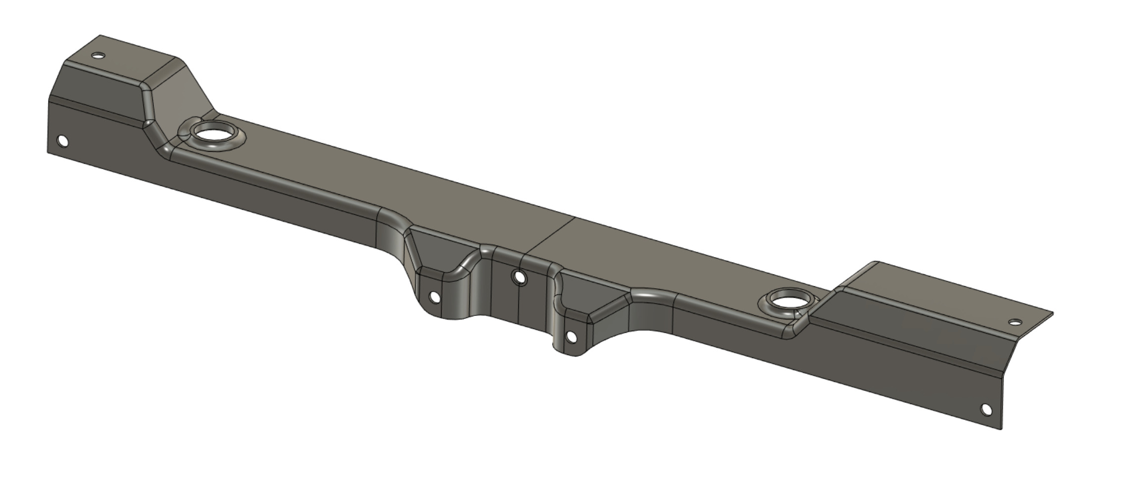
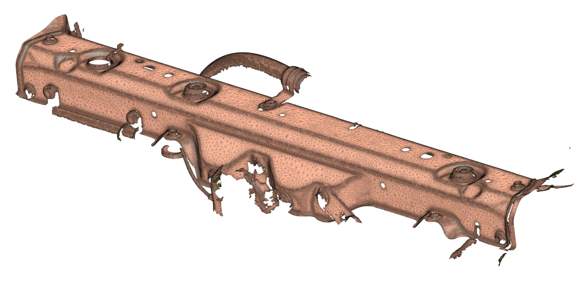
Ages ago a great guy named Rob from the UK sent me a 3d scan of an echo's radiator top cross member, when I was trying to figure out how to build an airbox without hitting stuff. It wasnt too useful at the time, as it was hitting the bonnet that was the problem. However! I just remembered, so dug it out as it's probably useful for new radiator. The radiator will be full width now, I cant run an airbox down the side. However the radiator is also shorter, so I can run an airbox inlet over the top. Which is probably actually a nicer solution. Hopefully all works out good, just got a prototype on the printer currently. Some of the extra bits on it arent needed anymore, like mounting points for aircon stuff.
-
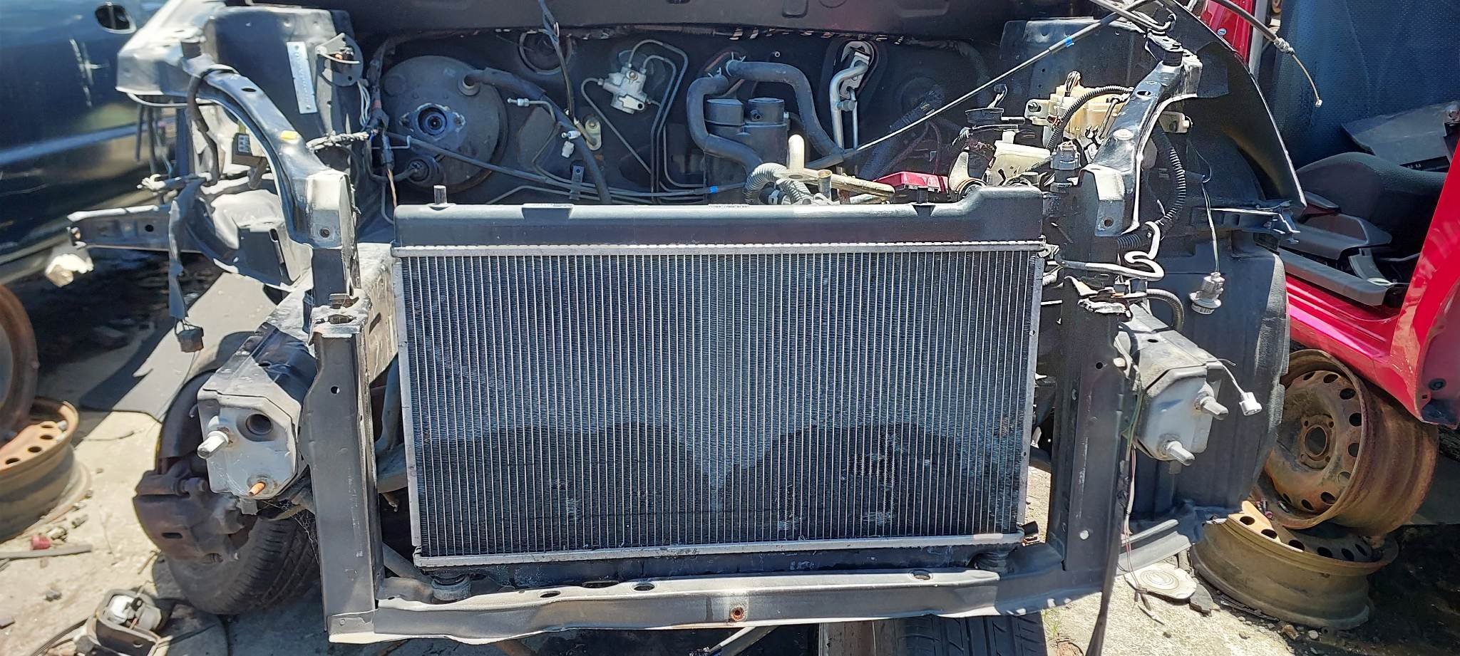
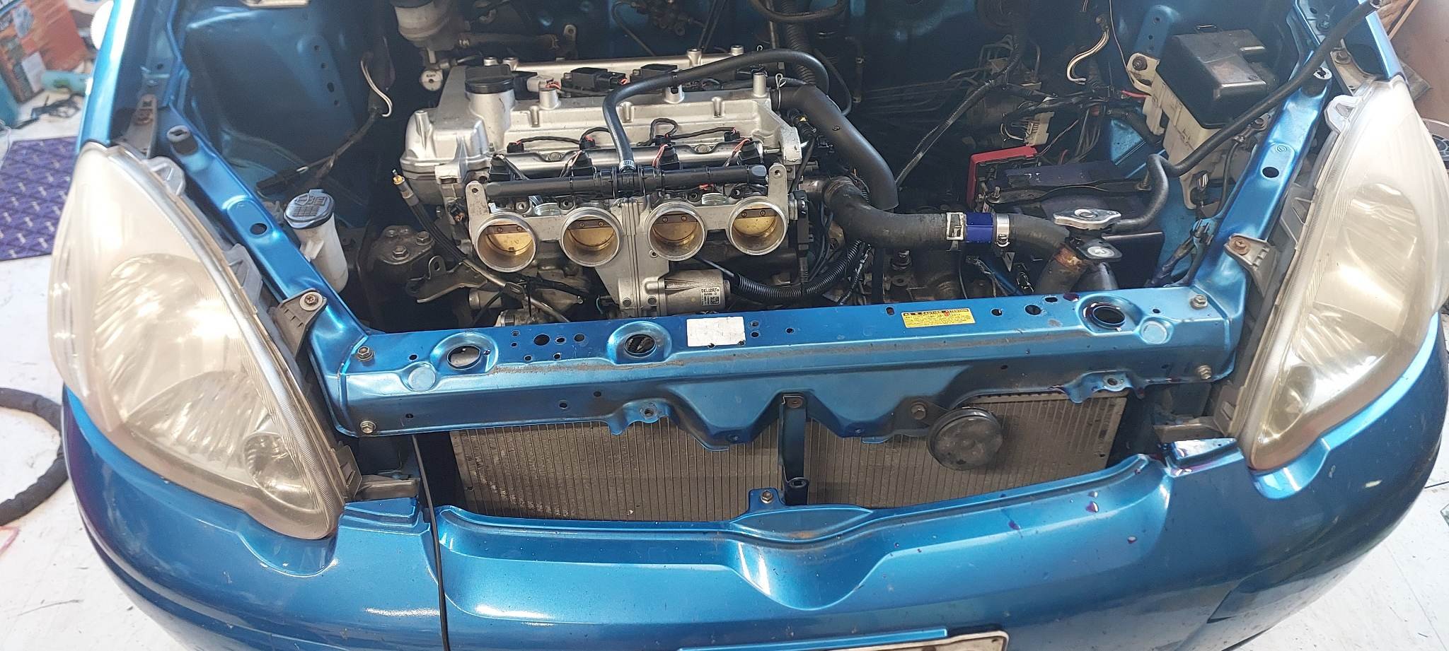
The next drag event is likely not until late January (either 4&rotor, or nightspeed, or a comp meet) So its time to get this up to scratch for another trackday in the meantime. (assuming there's anything to go to as well!) So I've dropped off my drag slick wheels to get the Michelin slicks put on instead. Rather than using the tall bumpstops that I bought (which were 85mm long rubber butt plugs) I think I'll use a similar setup to my drag day bump stops, to shim a shorter bump stop to about the right height instead. (Thanks Cletus for idea) The other major hurdle was the cooling system as the car only runs a partial width radiator, and to be fair I'd removed the side blanking panel so air didnt have any amazing incentive to flow through the radiator. What has been puzzling though, is that the top and bottom radiator supports have two sets of holes - It looks like its meant to fit a bigger radiator, but none of the various Toyota options with this chassis ever use a full width radiator. So doing some pick a part adventures. I found a Vitz RS that was already mostly apart, with the whole front missing. Then went window shopping for other cars radiators that might fit okay. First one I tried was too wide. Second one was from a 2008 Honda Jazz. Weeellll shit. Turns out the bottom pins/rubbers on the radiator are the exact size to fit the outer holes in the vitz/echo. If I swap over to the Vitz rubber bits, it fits perfect. Hah! Denso makes the toyota radiator, and also the Honda ones. So they must just have a template for sizes kinda thing. The hose sizes arent identical, I'll need to fit an aftermarket fan, and it's also a little shorter. So it's not exactly plug and play. But it also puts the top hose outlet completely out of the way of my throttles, which is handy for making an airbox etc. Have already got it in and holding coolant, have ordered a fan and will print something for top mounts. Easy! Happy with it! Also I noticed that the Vitz RS has these side ducting panels mounted to force more airflow through the radiator instead of around to wheel well area. So grabbed those too. Hopefully my cooling issues will be sorted. At the very least the temps should stay a bit cooler than before anyway. Also, I bought a spare bonnet for an experiment. When people add bonnet vents its usually a best guess to find the best area for them. You dont want it too far forward, but also not too close to the windscreen. But then it's hard to test even a handful of variations without ruining a bonnet. So on something like my Carina where spare bonnets are non existent, it's not something I'd really want to do. However in this case, there's no such anxiety about ruining a spare vitz bonnet as they're plentiful and cheap haha. I'm going to cut an absolute shitload of holes in it, and then cover them up all of the holes with a flexible plastic sheet (or whatever) taped down on the leading edge. So if the pressure on the top of the bonnet is higher than the bottom, the sheet will be held flat against the bonnet to stop air from flowing down in. But if the pressure underneath is higher, then the flap will lift. So rather than trying to guess where the best spot is, the airflow can tell me where it wants to naturally go. Again its another situation where you can do all the big brained calculations in the world, and still be wrong. Or you can do a dumb dumb brained test and get actual results that account for all of the real life variables. Ultimately it doesnt matter why something works, so long as it does! Before getting too far ahead of myself I'm also anticipating it might end up with some weird fluttering as various ones open and close but we'll see.