Roman
-
Posts
7,218 -
Joined
-
Last visited
-
Days Won
39
Everything posted by Roman
-
It's just a number I pulled out of my ass to show a comparison of engine rpm at that piston speed. That was somewhere around max rpm for each of those types of motor. As it seems a more meaningful comparison than the other way around (comparing piston speed at a fixed rpm) And yes I see I labelled it wrong, should be FPM.
-
Not too sure, havent weighed anything. However gut feeling is that it wont be meaningfully lighter than a 3S setup. Was using this calculator. Was using feet per minute as the units. Sorry if mislabeled it somewhere. https://www.omnicalculator.com/physics/piston-speed RB20 has a nice short stroke and a pretty good rod ratio.
-
Here's the remix.
-
HAHAHA This car is the gift that keeps on giving (Go to 11:20 if it doesnt automatically)
-
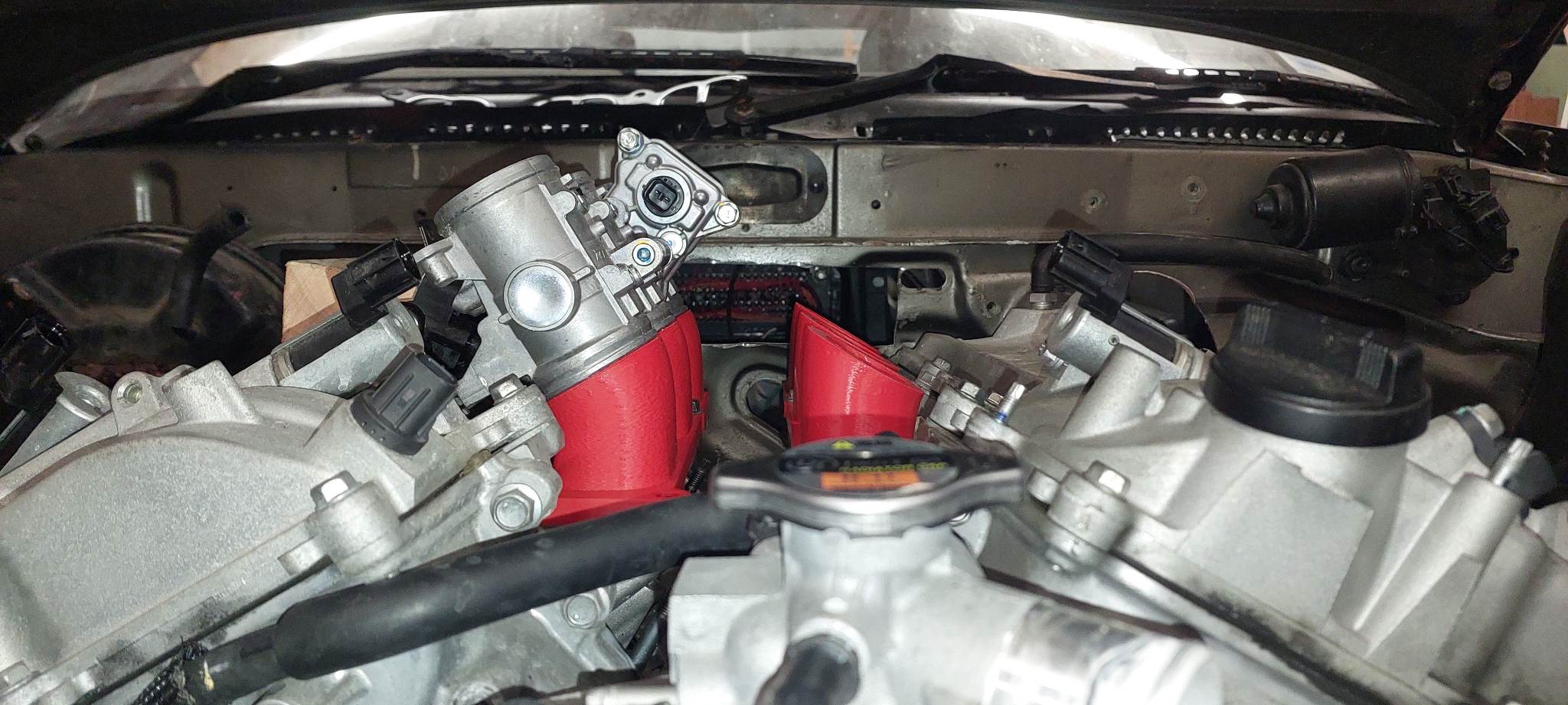
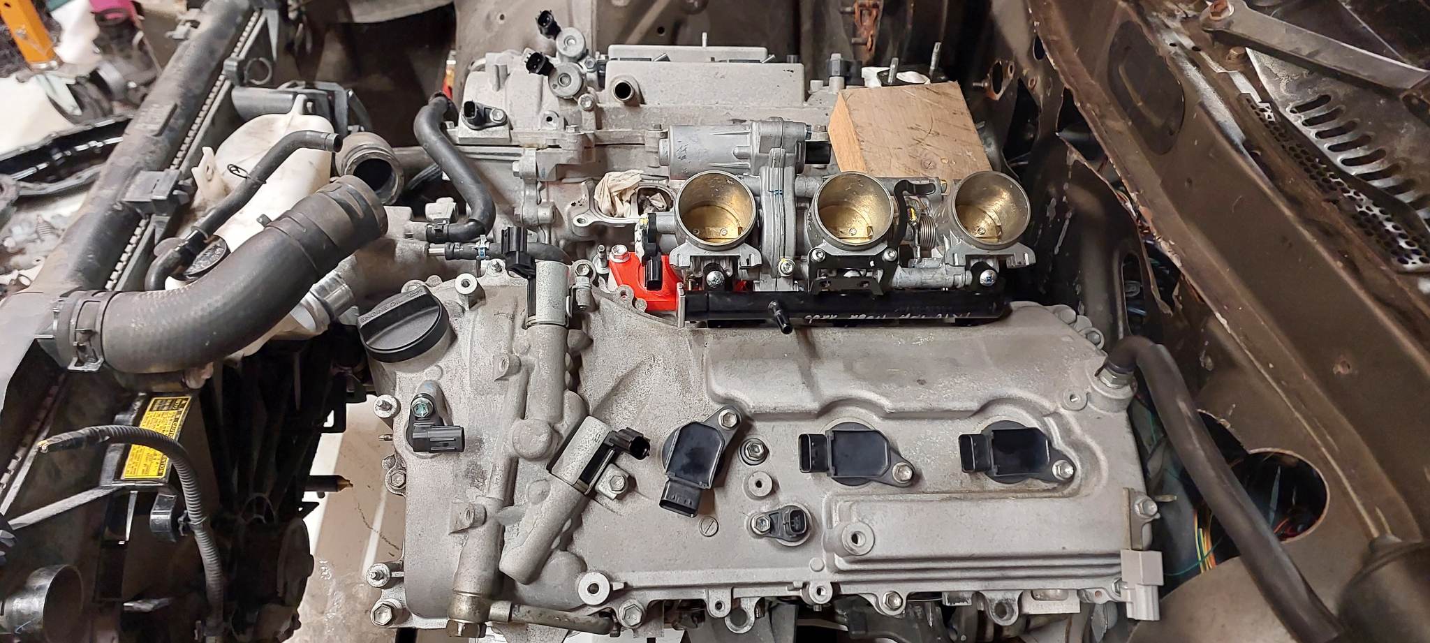
I cant flip them the other way because the fuel hose connection onto the fuel rails will hit the bonnet. The problem with standing them up too much more is that it limits me to something like a 20-30mm trumpet on the end. Not sure if that will be enough runner length. Although, the head does have quite a deep port. Key thing here is to try keep making progress towards getting a running motor. Then play around with all the variations on things for about 55 pages later on.
-
Ahh look at that luxuriously spacious 90 degree Vee! 60 deg vee makes life a bit more tricky for the intake. But, it also gives better room for the exhausts which is sorely needed. Win some lose some. It would be nice to be able to cross the runners across the vee like that V8. But that only works if your throttles are spaced apart at least as far as the ports. Where as my throttles are closer together than the ports. The other pair of throttles turned up today, as well as the H bridge controllers. Looks like I'll have way more room than expected if I want to make them more vertical or push them closer together. I'm desperately trying to avoid raising the motor any more, so the sump situation is taking a fair bit of trial and error. However I've got a setup that now clears the front pulley, the pan nearly fits okay (will push it back a bit further from the swaybar) Then still dipstick hole and oil filter to figure out.

-
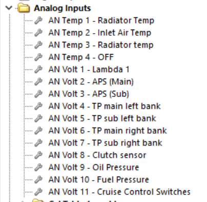
I'm not too sure, but I'll measure it when next in the garage. However I can confirm that it's bloody huge. @anglia4 my ECU actually only accepts a digital input for "clutch", so I'm actually using a general purpose output that then triggers a virtual on/off switch. Reason for doing it this way, is that matching the on/off switch to the clutch engagement point for rev matching or flat shift is super critical. So being able to adjust in software is super awesome. It's not strictly necessarily but it's an absolute life saver. I can add other analog or digital stuff over canbus as well, so not hugely stressed about running out of IO. It's mainly just a case of making sure that all of the mission critical stuff is direct to ECU where possible.
-
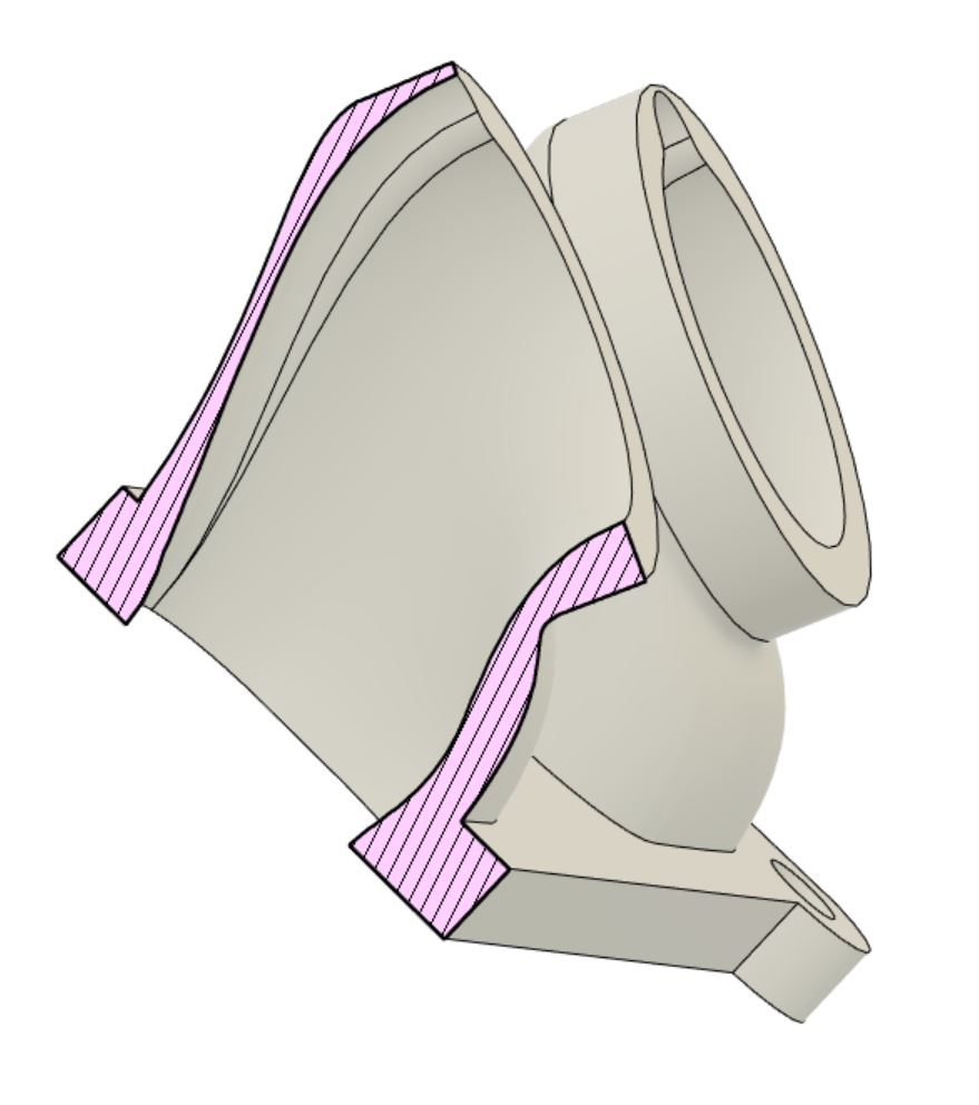
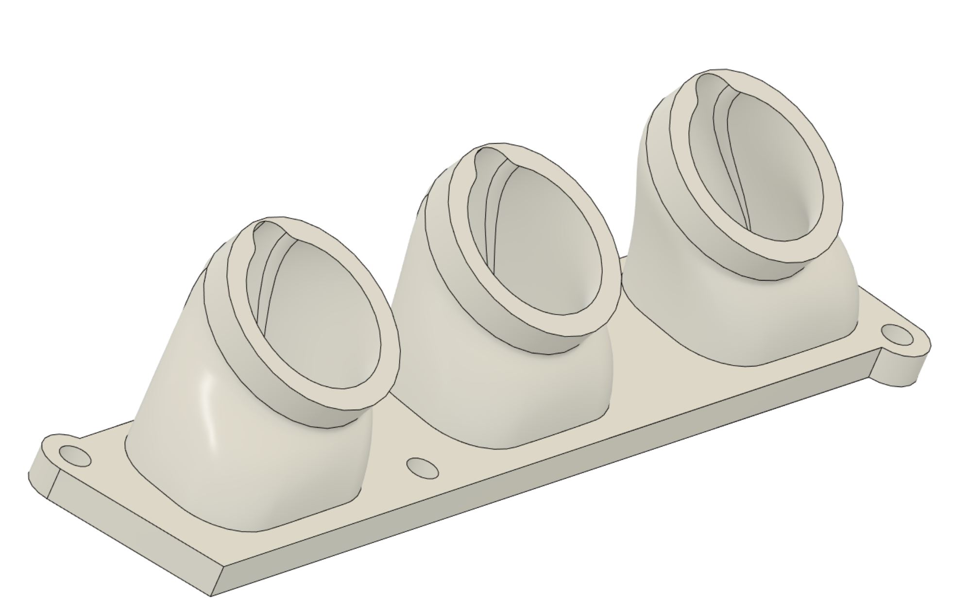
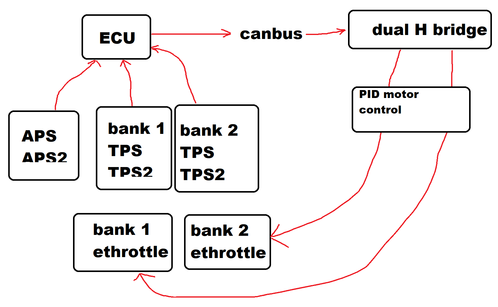
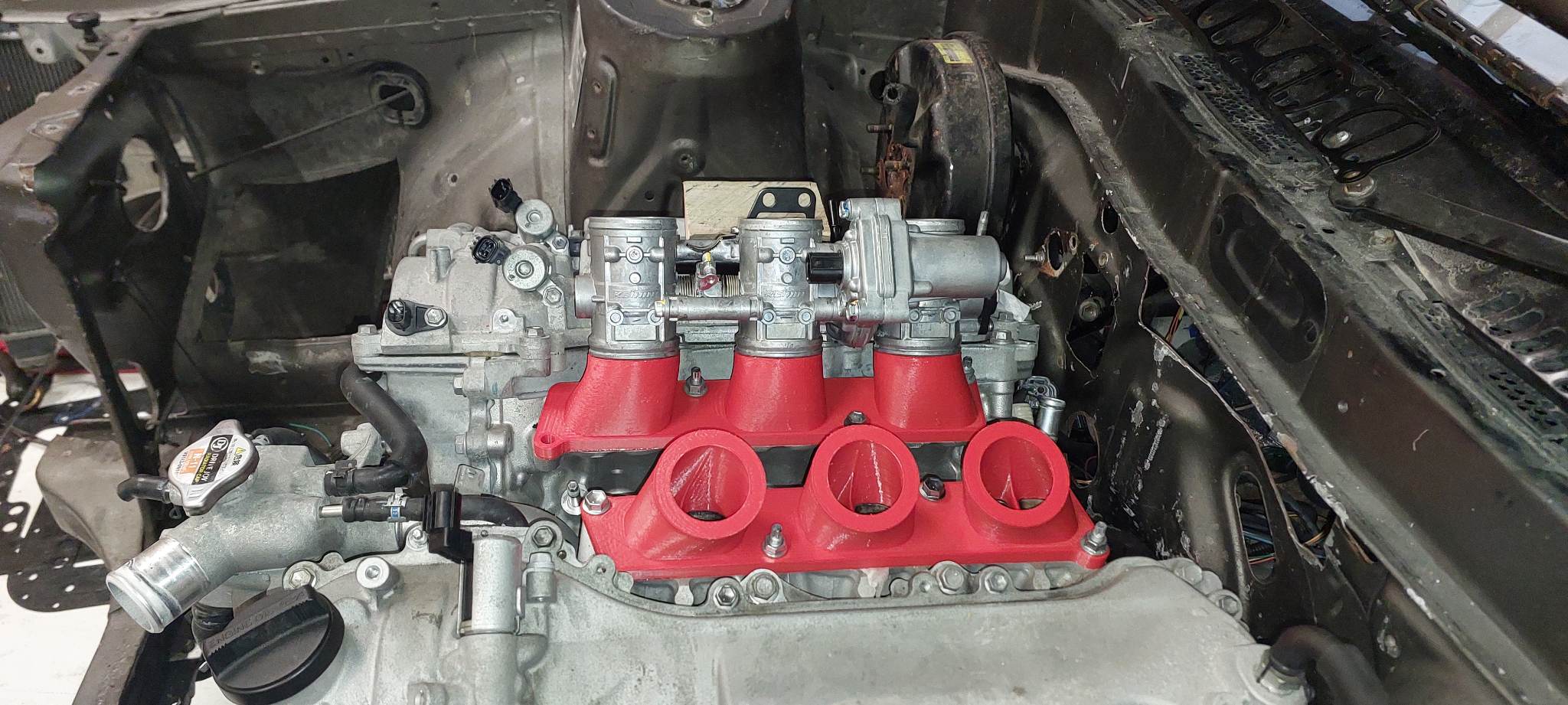
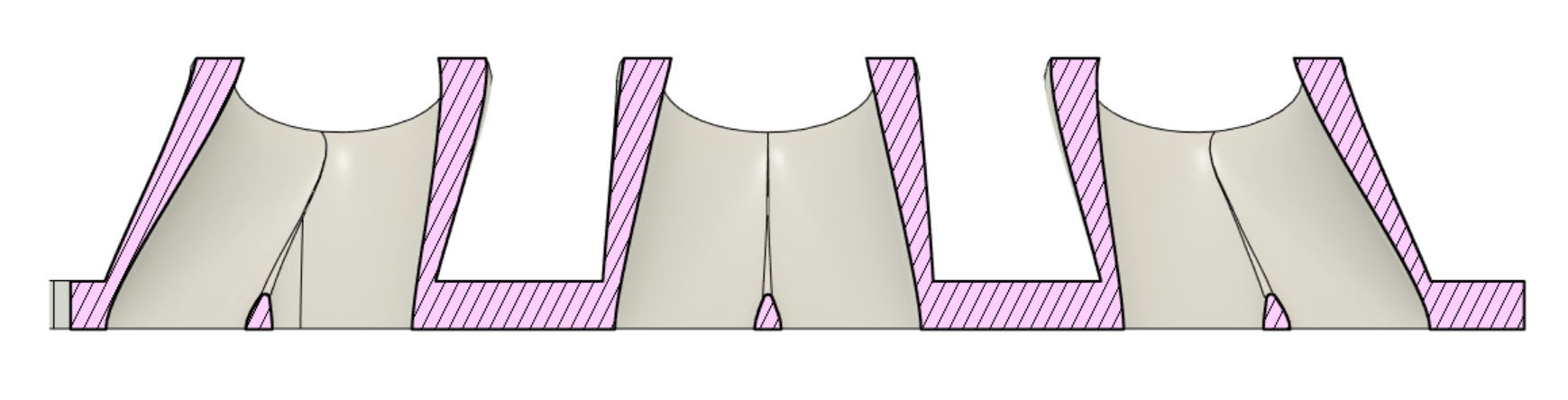
I'm pretty close to final version for throttles I think. I've pushed the pairs a little closer together towards the center of the vee, so hopefully still fits okay. I've added allowance for the injector and added 10mm of straight section to the top of the outside profile, for the silicone joiner to clamp onto. So although it looks a bit derpy on the outside shape, the inside shape means the injectors should be spraying more towards the center of the port rather than onto the walls. So that's nearly one job finished. Only about 50 other things to figure out! Also, I was talking to my Dad about ethrottle situation. He said that I should stop being a little bitch and just make something to control the motors over canbus (Actually he didnt say that, he's a great person) But, yeah, it's not actually all that complex to control a DC motor with a PID routine and an H bridge I guess? Then I could add a feed forward table so it works better than the standard setup. The MaxxECU actually has a way better e-throttle control scheme than Link does, in some good detail here: https://www.maxxecu.com/webhelp/settings-ethrottle-throttle_control.html So I might be able to make it work a bit better than standard. Will get someone smart to review my code though so I'm not gonna kamakaze myself into a wall because I divided by zero or something. However, the ECU would still be accepting all of the inputs, and still be in control of safety shut off features like killing power to the e-throttle relay if it sees a fault. However this does mean that I'm absolutely nuking my ECUs allocation of analog inputs. So if needed I'll try push some more stuff to canbus, and keep critical things direct to ECU.
- 130 replies
-
- 23
-

-
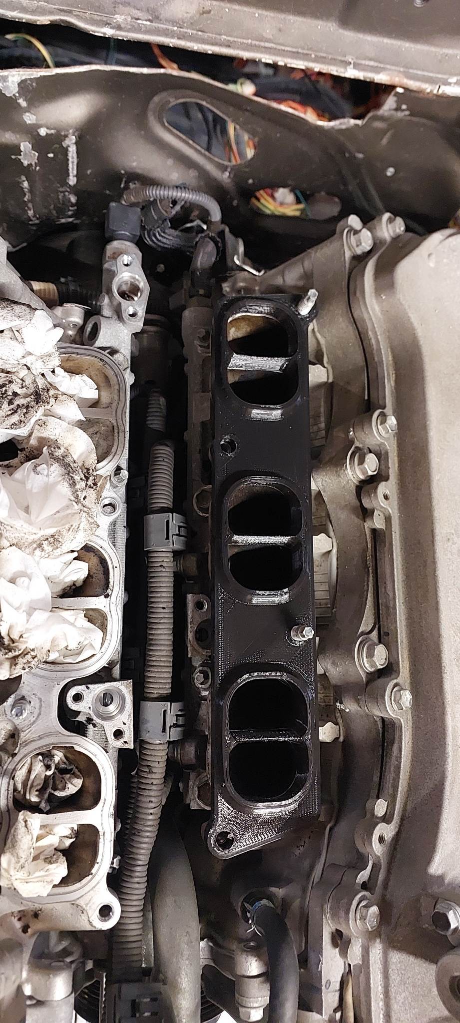
I will do the same trick as before, print with Nylon PA12 and then wrap with carbon fiber. This time I'll add some crush tubes so the bolts can do up tight without having to be precious about overt tightening them.
-
I got both sides fitting nicely. Sweet! I guess I should try find some injector plugs and TPS plugs that suit the bike, hopefully they're fairly generic.
- 130 replies
-
- 36
-
-
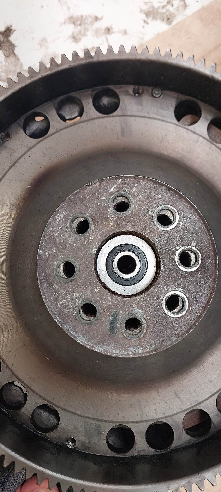
Yeah welding it isnt even really an option, because it's super thick there. As this replaces a dual mass flywheel. But that's also what gives me some confidence that it's not going to blow to smithereens either. Alternatively I could drill new holes in between centers of existing, but I think slotting would likely be the better option. The consensus of internet facts(tm) seems to be that so long as you're slotting outwards rather than inwards, it's okay. @shrike I think the radiator will be fine, will just mix and match hoses to make it work.
-
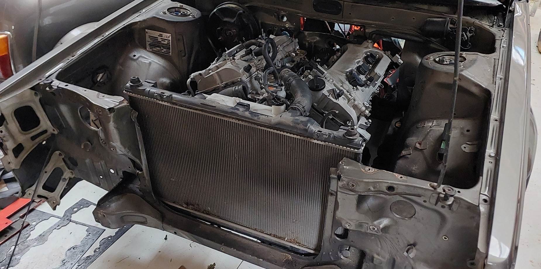
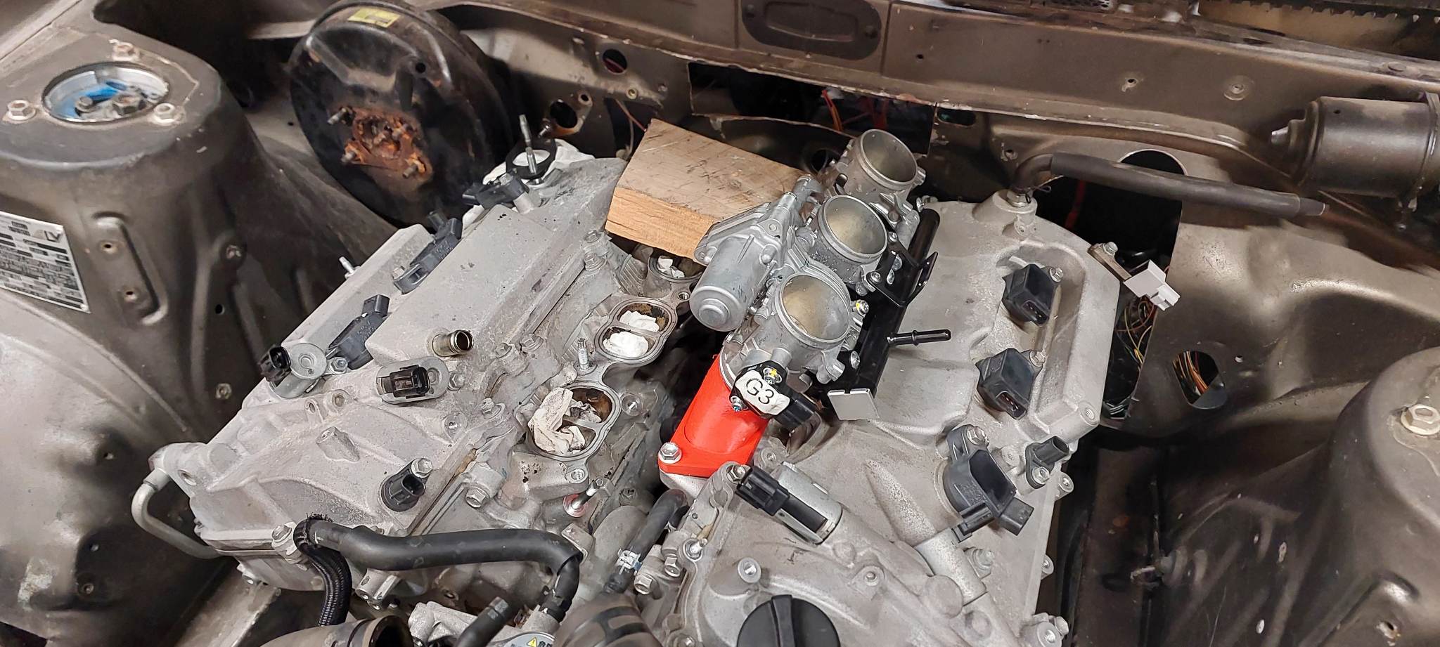
Few bits of scatterbrained progress, on everything but the sump. haha. I pick-a-parted a Mark X radiator and fan assembly, as the radiator hose sizes on this motor are real big. It's pretty big, but it clears the bonnet. Sits too high for the hoses to line up which is a bit meh. But, keeps things simple in a lot of ways I guess. Also one set of throttles turned up. Took some quick measurements then printed just one runner to test fit. Has an alriiiggghhhttt amount of clerance to the bonnet. But these throttles actually have a massive head height above the throttle plate. So I might machine them down a bunch, so I can start a curve on the runners earlier. Just printing another iteration that's about 10mm taller, and a little less angle. The throttle spacing is not quite as good as my guesstimate with the 1NZ / S1000RR throttles. Should be alright but longer term will probably try come up with something that keeps them all straight. Also, I'm glad I didnt jump the gun and buy a 2GR or 1GR or whatever flywheel. It looks like all 3 motors have different PCD on the crank. Which is good news for me, as the 4GR is closer in spacing to the 3S than the 2GR is. With a real life measure / eyeball it's probably close enough that put my chromoly flyhwheel on the CNC machine to slot the holes and it would be sweet. This would make life a bunch easier for the gearbox situation as well. As the other FWD flyhweels dont have allowance for a spigot bearing that the J160 needs. Also some random trivia, there is a 4WD Mark X. As seen at Pickapart. Unfortunately the sump is considerably less useful than my existing one, and looks like a bastard to get out. I dont know why a 4WD Mark X needs to exist, 210hp in a 1600kg+ car surely makes for a pretty sluggy driving experience. I've gone through a few more iterations of trying to simplify the sump situation but I'm not quite happy with it yet.
- 130 replies
-
- 27
-
-
Well I think we can consider the Alfa 155 DTM as the real life version of maxxing it out for a 2.5 litre V6. So around 365kw... 196hp per litre!
-
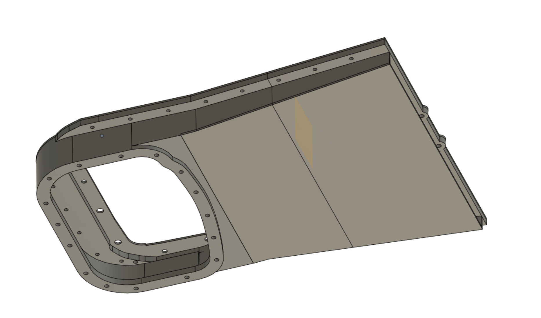
I have had to narrow up the sides a bunch, as it's tight for clearance where the steering column is, and the brackets for the steering rack. However, getting closer towards a workable plan. One annoying thing is that the edge of the front pulley hangs down lower than the bottom of the motor, so will need to allow a notch or whatever. Will move the oil pan about 50mm forward of this point so its got heaps of clearance to the crossmember to make life nice and easy. This will also mean I will be able to weld a little upstand piece on it, to fit the 3SGE dipstick as well. Then the only hard part left is figuring out the oil filter lines.
- 130 replies
-
- 24
-
-
If you have a steep valve angle, as in, the valves are more vertical. Then you need absolutely insane amount of lift and overlap in order for both of the valves to hit. At full intake cam advance, my intake valves are chasing the piston down the bore as close as they can. So hitting exhaust cam isnt the limiting factor.
-
I whole heartedly encourage graphs and wild specualtion
-
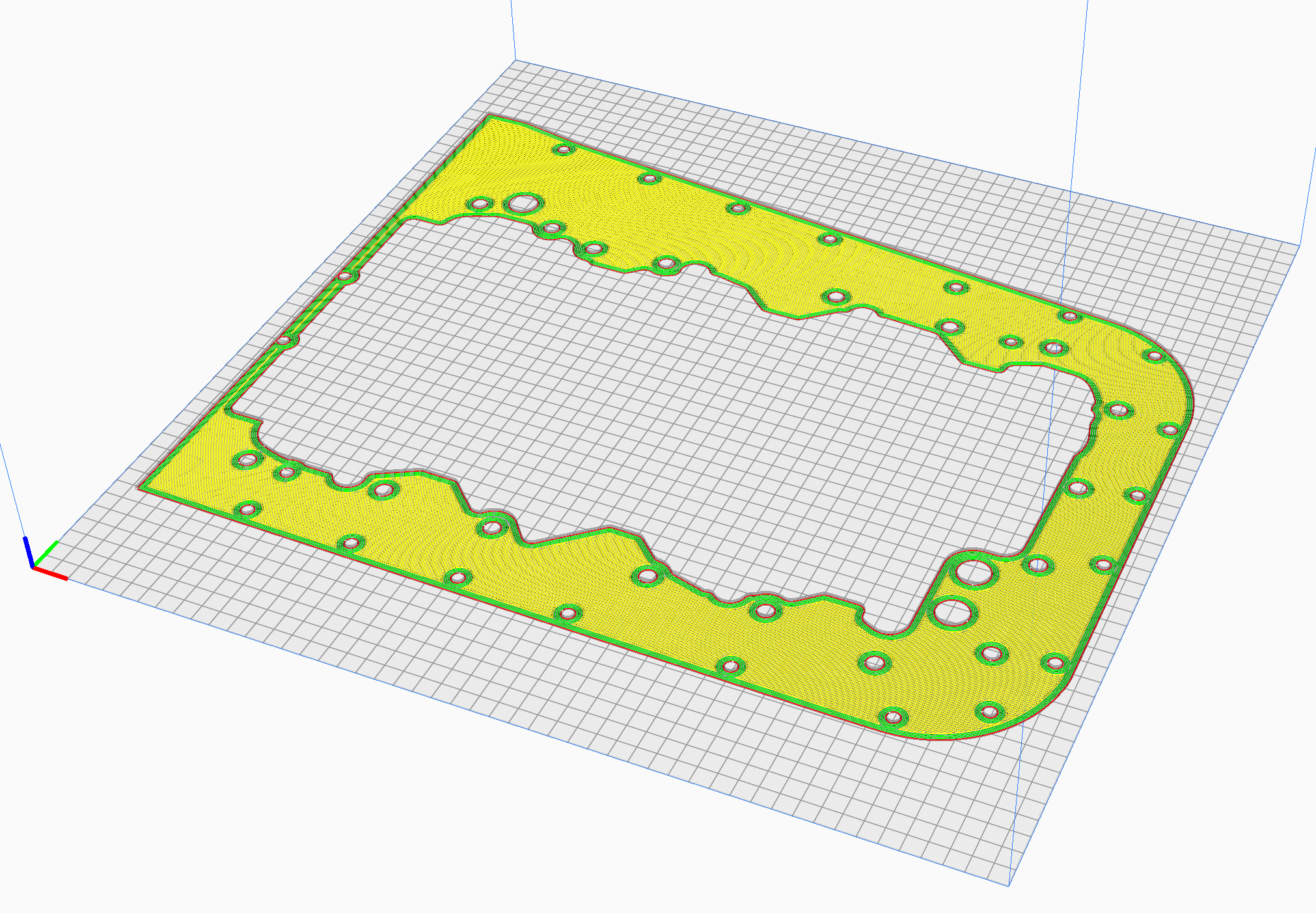
I somehow messed up my sump scaling. I printed the first half of it, and it was about twice as big as needed haha. So started again from scratch because it messes things up if you just try rescale it. So the good news now, is that I can fit whole sump on the printer at once. And the beams oilpan might fit pretty awesomely to the shape. See how it goes.
- 130 replies
-
- 24
-
-
Also, something has been boggling my mind a bit. Lets say you have two 2500cc engines, one is 4cyl and one is 6 cyl. Lets say they are both doing 6000rpm and both have 100% VE at full throttle. Does the v6 make more power because its breathing more air in, because its got more cyls and more valves? No, because they have exactly the same amount of airflow going into the engine. As displacement is the same and VE is the same. The V6 just cuts the pie into more slices. So what's the point then? Well, hopefully with a V6 at high rpm the VE number can stay higher as rpm goes up, as there's more valve area. So for example a K24 motor has a 36mm valve with a 5mm stem, a total valve area of 7984mm2 with its 8 intake valves. A 4GR has only a 32mm intake valve, and assuming 5mm stem as well. On total area it wins by 17% with a total valve area of 9408mm2 with its 12 intake valves. So hopefully the idea is that when the 4 cyl motor's valve area starts becoming insufficient towards higher rpm and VE drops off, the V6 still has enough valve area to keep flowing well. I'm really pinning all my hopes and dreams on this motors ability to rev really high, as it's the only real upside to this big chonka. It's still possible that there's some fundamental reason why it wont be able to. Like maybe the crank will break or the oil pump will explode or whatever. Also, I am very cautiously making comparisons to a K24 because it's unlikely that it will make power as good as a K motor setup will. But, forgetting the power figure. What if it does rev well and everything's okay, and its absolutely massively awesome? How good! That daydream is alluring haha.
- 130 replies
-
- 20
-
-
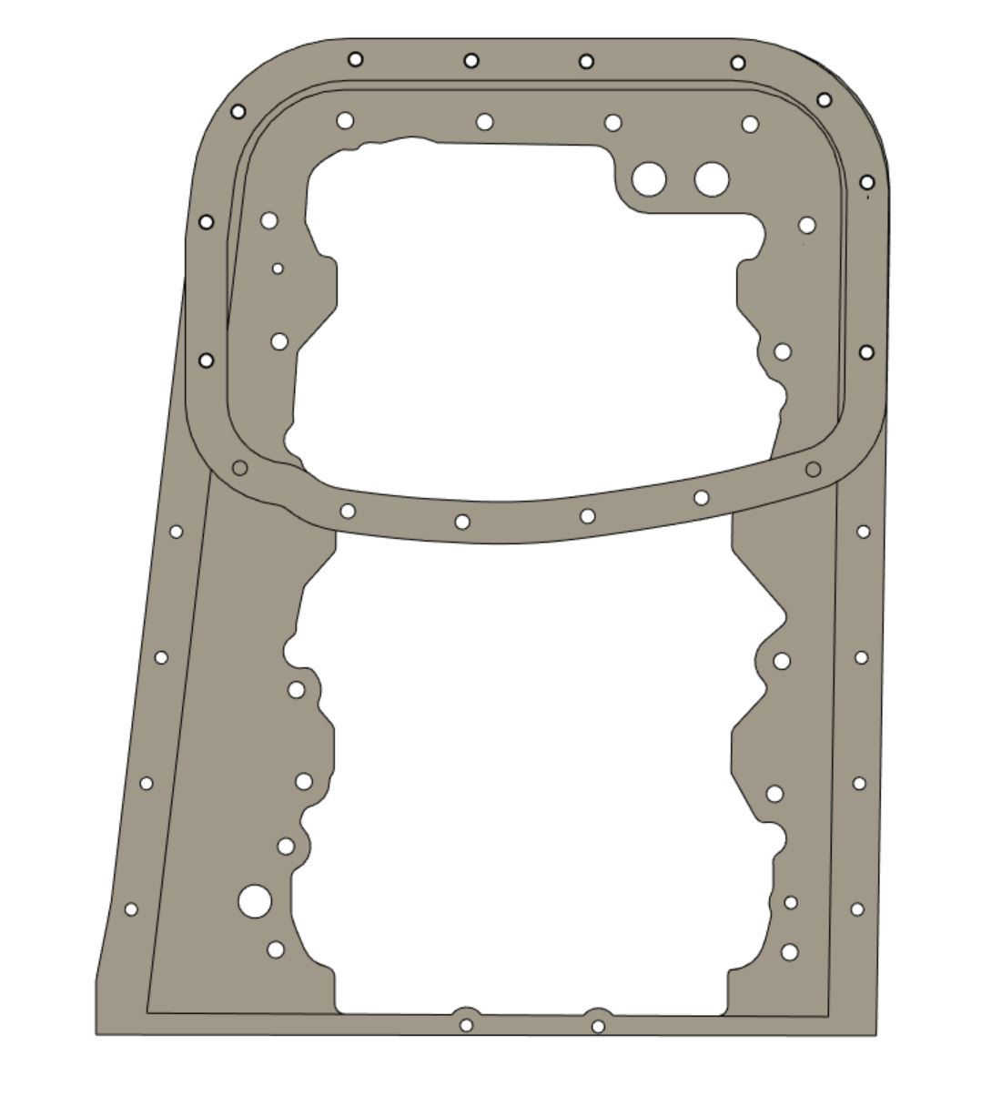
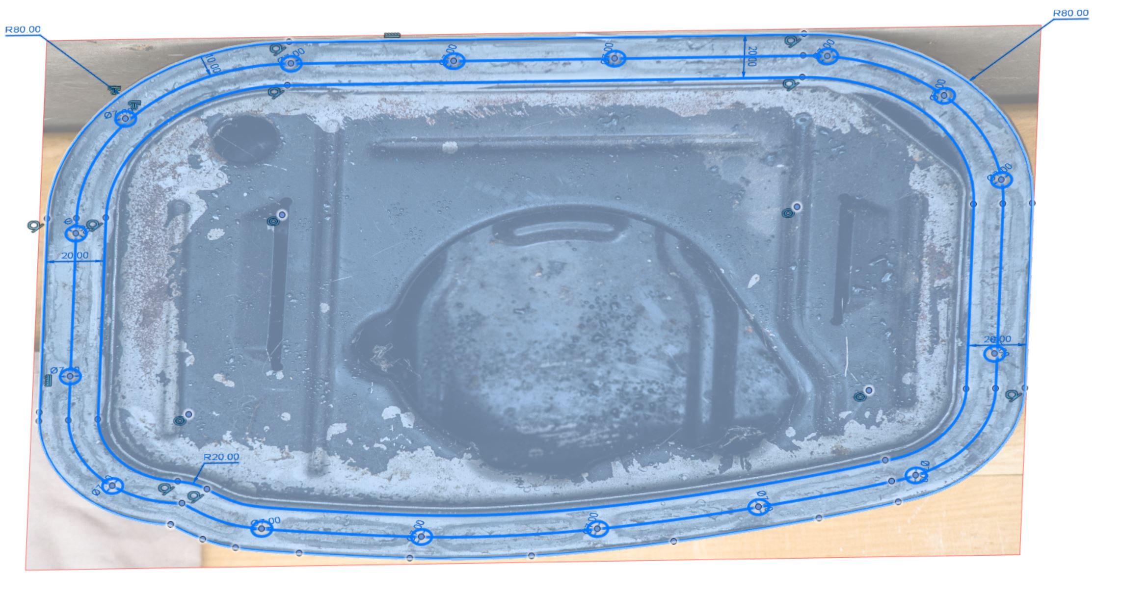
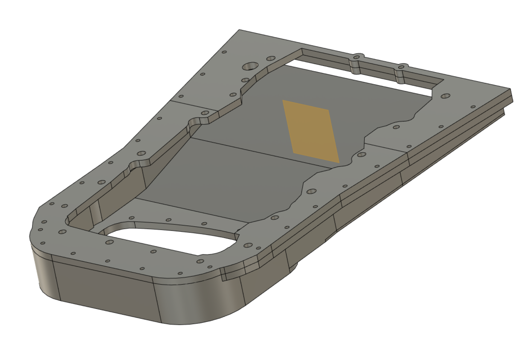
My trick for drawing from a scaled picture worked out really well! It's not perfect, but drawing from measurements alone it would usually take me a few iterations to get this far. So I decided I'd try the same trick for getting some measurements and shape from the beams 3sge oilpan which I'm planning to use. So as mentioned earlier, taking a photo from far back and zooming in, and trying to get as square on as possible minimizes distortion and gives a more accurate image to work from. Then I added that shape and measurement to the model I'm just printing the front part of the flange that fits to the motor, to see if it's all looking good. Then I'll print a bottom front part and see if everything's sweet, and if it's possible to do up all the bolts. Then go from there.
- 130 replies
-
- 19
-
-

-
Must have been heart breaking to see that spray on the seats. Stoked that the insurance came through on that!
-
Hey @Hemi, It doesnt do that stuff automatically. What I did prior to the start of that video, is that I found an image that was nice and "flat" as in, had minimal perspective distortion. If you are standing really close to something when you take a photo, the center part of the image is closer to the camera than the edges, and you're viewing everything less parallel. So you get distortion of sizes. Fish eye lense is an extreme example. If you stand further back and zoom in, then you get everything propertioned more correctly as this effect is minimized. So, thanks to the random internet photographer person who took those nice photos of a 4GR block, I had a good image to work from. So once you've got a nice photo, you need to import it into the program and then tell it how big it is. So normally you pick between two known points, and enter a dimension - then it will rescale the image to that distance.
-
I put together a quick(ish) silent film showing my methods for designing and 3d printing manifolds. Maybe helpful for someone trying to prototype something. Basically, if you know how to use lofts and fillets you're golden haha.
- 130 replies
-
- 16
-
-
-

Hyperblade's KP61 Racecar "KP61R" Discussion
Roman replied to Hyperblade's topic in Project Discussion
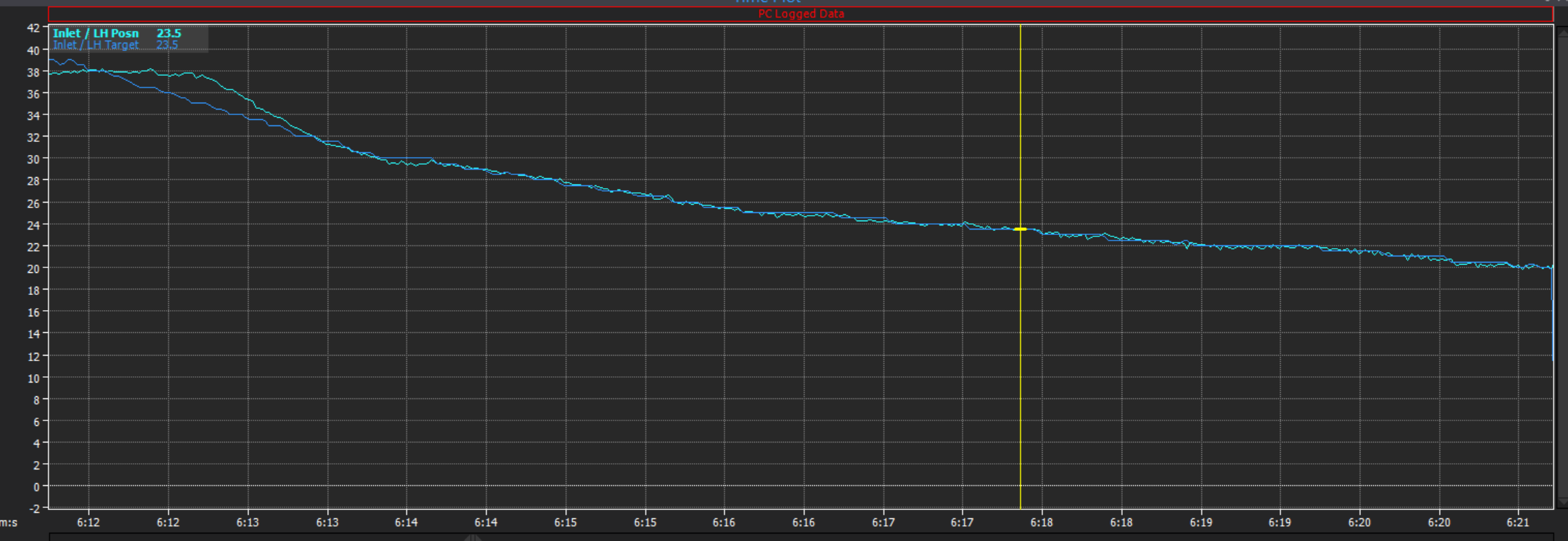
This is not from his engine, but from a Toyota VVTI setup. Can generally stay on target within 0.1-0.2 degrees, but needs to catch up on fast transients - cant do much about mechanical latency. But the Link PID works well, there is a compensation table for oil viscosity when oil is cold.
-
I'd be happy to try one if I could find one! Strength issues, dunno. Will have to see if that's an issue, although I'm not sure how it would present itself.
-
Yeah will do it how the factory pans do, will just cut a groove then use sealant. Will have o-rings on the interface to the oil filter in/out lines. (again as per factory fit)


.jpg.a12c03a26a295944c07eef4c45bfbd80.jpg)