yoeddynz
-
Posts
19,489 -
Joined
-
Last visited
-
Days Won
158
Everything posted by yoeddynz
-

Discuss here about Yoeddynz's little Imp project...
yoeddynz replied to yoeddynz's topic in Project Discussion
A bit like the unequal tracts on a earlier scooby to create the off beat rumble ? But in the case of almost all Porsches and all Goldwings they have very equal systems yet still create the sound I want. I am getting closer each time though and what Ben has to say below is similar to what I'm planning next... -
Yoeddynzs 1965 Hillman Imp. Chasing Flappy whirrs
yoeddynz replied to yoeddynz's topic in Projects and Build Ups
I've now clocked up 3200km since fitting the flat six. 1200 of those are from the weekend just past but I'll get to that in a later. First off - more exhaust box modifications. Adding that sound deadening mat around the pipe had made it too quiet and the exhaust note had lost some of its character. So I cut the box open again and removed the stuffing. This time I riveted a lid in place in case change my mind..again.. I also cut a hole in the bottom of the box and made a bolt in panel that has a folded over, wedge shaped partition splitting the main lower chamber in two. The idea is to stop the exhaust pulses from each side hitting each other and creating that hum. I don't really think it will work as such because they are pressure induced sound waves and the partition isn't a perfect seal. But it does help guide the exhaust flow up through the plate of many holes above. I didn't take pics so you'll have to picture it. So the box is sort of back to what it was like when first made but in theory better flowing. It sounds nice enough though, not droney at all, no fumes and sporty when extended. It'll have to do until I start exhaust box number 3. With that bit of exhaust fettling finished I double checked my tool box for anything extra we might need, packed the car up and cut some thick foam up to make a cradle for the UE Boom bluetooth speaker so it doesn't slide about on the parcel shelf. We headed to my mums place in Blenheim, Hannah driving convoy in the van which was filled with the last of our K11 micra bits that were getting picked up from mums by the new k11 owner the following week. She had Kevin the cat for company as mum would be baby sitting him. Pic from a stop at Pelorus bridge on the way over.. Kevin.. The drive over was great fun. I was lucky enough to almost get a clear run up the Whangamoa hill climb until I caught up to a Suzuki swift sport that was not living up to its name. For those that don't know the Whangamoa hills its a decent climb out of Nelson that's got loads of great corners where you can see well ahead. The whole road up to the saddle was resurfaced a few years ago and its a sporty drivers delight. The following day we headed south to Christchurch. Hannah had a weekend long fire fighters conference to go to. I would be free to catch up with family and friends down there. Lovely drive south with perfect weather. We've not been down the east coast for a few years and this was the first time in a very very long time we'd driven anything interesting on this road. Pics.. View from cafe stop.. Had a very nice posh hotel to stay at in Chch. Car was now plastered in fly road kill.. The next couple of days I hooned about chch city, caught up with friends. First thing Sat morning I popped in to mag and turbo and got my front wheels rebalanced as I could feel they were out slightly on smoother roads. Big thanks to @CUL8R for sorting me out there, getting the right fella (a mini loving barry) on the job. Was nice to catch up for a good old chat. The cars front end was much improved. Sunday was especially good as I managed to get some really good driving in on the Port hills and Lyttleton habour area. Good coffee, great roads, clear sunny day. I have not driven a lot of these hill roads for years and the last time at speed was in the 90s in my supercharged Mr2, brothers TVR or a bit more recently a mates WRX he lent us for a week. Great roads and luckily actually really quiet on the Sunday morning. I discovered whilst hooning through the Lyttleton tunnel that if I hit the red line in second then button right off so fuel cut activates the car does a wicked backfire. Second time back through the tunnel was hampered by someone who insisted on sitting at 40kph. Late morning whilst parked up looking at the maps on my phone six Triumph TR6 sports cars raced by. I dropped my phone and took off after them. For the next hour the convoy raced about making the most of really good hillclimbs and twisty roads. Damn it was fun. What glorious sounds! The Imp was in its element and by now I was really getting the hang of making the most of the rear engine configuration. I was bloody loving it. I just kept following them until we ended up out over in Charteris bay and they pulled into a cafe car park. They all came over to check out the Imp, wondering how I managed to keep up Lovely cars TR6's - my brother almost bought one that we'd test driven before getting his TVR. The Triumph 6 connection for me is having owned 5 TC2500s over the years. Turns out I had met one of them a coouple of years previously when they were doing a nationals meet up our way. I was invited in for lunch with them and had some good banter. Late Sunday afternoon after Hannahs conference was over we drove to Hanmer springs. Another nice Hotel and this time the Imp had company more its age.. That evening we spent several hours in the thermal springs right over the road from the hotel. Cool clear night. Tickets now include the water slides so we made the most of those too. On Monday morning we left Hanmer.. and headed back to Blenheim via Waiau.. and the inland Kaikoura road. It used to be gravel for quite a big section and I've not driven it since it's been sealed. Looking forward to the twisties but it was quite a let down. Actually very rough, lumpy and bumpy. It was not really suited to a lowered imp. Would be far more fun in a peppy Citreon or something with really supple suspension. In fact I had more fun when it was gravel. Kaikoura for lunch.. Back to Blenheim for the evening. Got to play with mums border collie puppy .. Following day it was back home. This time I was even more lucky on the Whangamoas because there was a traffic stop due to tree felling. I was at the head of the line just behind a large truck. Passed him after the lights went green and had the whole hill to myself. Fantastic. Gentle 4 wheel slides balancing that rear weight overhang on the smooth tarmac. So fun. Once home I did a final check over of the car. Needed a tiny bit of oil, 200mls, due to a small drip from the sump I have now fixed. We clocked up 1280 kms (having accounted for 3% speedo error) and across all that driving averaged 6.6L/100km or 42 MPG in old money. Of the fill ups the best was 5.9L/100km when just cruising with the traffic down the east coast, worst was 7.4 after a lot of fast driving. I'm bloody amazed. We kept re-checking the figures etc and its legit. Its just so cool that such a smooth, nippy little six can also be so thrifty. The Imp is also really comfortable (the Recaros help) on long trips too. Its the only car I have owned to date where I don't get a sore right ankle from the throttle on long runs. So I'm pretty bloody rapt with the outcome and look forwards to more road trips. Also looking forwards to cracking on some more modifications I have planned.- 120 replies
-
- 46
-

-

-
Just a thought which may or may not work (and could end up looking ugly..) but can you fit tiny nylon balance tubes between each bank?
-
Discuss here about Yoeddynz's little Imp project...
yoeddynz replied to yoeddynz's topic in Project Discussion
No real opposition to the side exit. From the very beginning of starting this conversion I just always had the picture of this setup having the twin centre exits and I prefer the look of them But fumage Quite keen on seeing what two corner exits might be like with regards to the airflow wisking away the fumes. -
Discuss here about Yoeddynz's little Imp project...
yoeddynz replied to yoeddynz's topic in Project Discussion
I sort wish I had started that way! I have spent more time making exhausts than actually driving it. God knows how much of my life this thing has taken actually. But this is oldschool And its fun. -
Discuss here about Yoeddynz's little Imp project...
yoeddynz replied to yoeddynz's topic in Project Discussion
yeah aware of that. But even if I extend them quite far out its still going to be an issue I believe. But they are bolt on units so I can certainly try longer ones in the future. Its a problem many Hillman Imp owners have had due to the not so fantastic sealing quality of the rear opening windows etc and all the owners who have gone to side exit exhausts fix the issue. The power of the low pressure zone is strong in this car The other day I went for a hoon after the council mower man had cut the verges around the bay. I got home and the engine bay was full of cut grass! All sucked up and through the vented engine cover -
Discuss here about Yoeddynz's little Imp project...
yoeddynz replied to yoeddynz's topic in Project Discussion
You're probably not wrong. I actually copied the flowmaster muffler design for the Datsun A12 and apart from it now rotting out because made of zinctec its a good sounding muffler.. I took the Imp for a good thrashing this evening up the up the Riwaka hill, over and back. Caned it heaps and its interesting how the exhaust note changes as the muffler gets some real heat in it. Worked the brakes hard and the front pads are properly bedded back in (but will be replaced anyway) Got home and straight out with the temp gun. Front brakes perfectly matched in temp, rears only about 3 degrees out side to side. Really good to see. I'm still going to design another muffler setup because its a fun thing to do. Got some ideas on how to modify the original one for better sound too - although I'll never be able to design away the fume problem from its centre exits so it'll never be good for summertime windows down cruising. -
Discuss here about Yoeddynz's little Imp project...
yoeddynz replied to yoeddynz's topic in Project Discussion
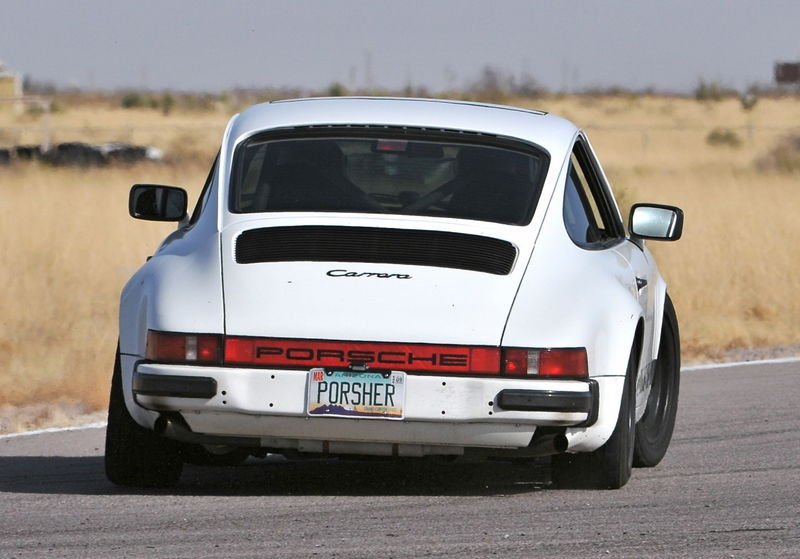
Oh also - for @Roman and anyone else who likes graphs.. check out the wall of text and graphs that Bill Verberg loads up on this thread I found in my searches... http://forums.pelicanparts.com/porsche-911-technical-forum/592353-mid-engine-exhaust-design.html -
Discuss here about Yoeddynz's little Imp project...
yoeddynz replied to yoeddynz's topic in Project Discussion
Yep .. "This time I filled the cavity around the perforated tube. I'm hoping it might quell some of the 'hollow cackle reverberation' sounds" Edit - I've just realised the build thread is missing a photo I took of me adding packing into the chamber with the perforated tube. -
Discuss here about Yoeddynz's little Imp project...
yoeddynz replied to yoeddynz's topic in Project Discussion
I'll check that out but I think the headers are fine because it sounded pretty bloody cool when bench testing, both without mufflers and with some in place. But was probably too loud and not the most practical packaging They are the two mufflers that came with the engine. It did have a small balance tube installed between the original headers. The jury is out about balance tubes on flat sixes. From what I have absorbed they are not needed at all for performance gains but can help for a certain sound. My current exhaust box effectively has a balance chamber but as I have noted this is possibly the cause of the resonance. The previous exhaust box had none of that type of resonance but being a straight through it suffered from the drone sound I pretty much got rid of using the J pipes. But to me it sounds just like a straight six until around 4000 rpm. Engine with just the old mufflers loosely sat in place over the ends of the headers... Same setup at idle. Sounds exactly like I want... I'm trying to design another setup that has these two mufflers or similar (because I have actually given these to a biker mate) mounted across the back, with an exit out each side sort of like this
-
Update on this little beauty from the new owner. He's loving it. He's just got it a new COF, has got himself a truck licence and a TSL and is now in the process of tidying it up. New deck installed and he and his wife are currently stripping the old paint off it in preparation for new paint. I'm super happy it went to them and really glad to see it getting some love.
- 4 replies
-
- 22
-
-
Quite annoyed that you just go slapping on a couple of hotdogs out back and your exhaust already sounds more boxer than mine... I might copy.
-
Yoeddynzs 1965 Hillman Imp. Chasing Flappy whirrs
yoeddynz replied to yoeddynz's topic in Projects and Build Ups
More exhaust tinkering. But first I decided to make some new front caliper brackets. The race car I first bought came with a set of 80's CRX sliding calipers and vented rotors. 231mm/17mm thick. They work really well. However the brackets they bolt to are only held on to the uprights with two of the original drum brake mounting holes. This is actually the way many of the disc brake conversions sold for imps over the years are done but I've never been super happy with it. The holes they mount through are spot faced and quite close to the edge. My fear (yes possibly a bit paranoid but) is that the casting could break and the caliper bracket get pulled away under heavy braking, jamming the caliper in the rim and locking the wheel. You can see the setup in this pick I took not long after getting the race imp... There is better, more fail safe way to do it using all three mounting bolts, which is also stiffer and also modular. I bought some 10mm steel flat and got to work. Drilled and bored the centre hole to exactly match the axle size.. This way the brackets will always sit perfectly central and even if all three bolts let go (is a very super paranoid way) the bracket would still stay in place concentrically. I didn't take many photos of the build, a process that ended up taking way longer then I expected but hey, that's car projects. Here's the bits on the bench as I'm measuring out and marking etc etc.. The finished parts before paint... Only down side is the extra 380 grams of unsprung weight per side However, on the plus side I do get to inform the various Hillman Imp doomsayer Barries out there that I have added more weight to the front of my car so I wont end up in a hedge next time I attempt to corner it I shimmed them up to suit ( for the final install the bolts are reversed and lock washers install btw) Test drove and its all good. I really need some new pads though because old pads are worn to suit the old brackets which I had noted were slightly bent. The new setup is far stiffer. The original pads are rock hard anyway and have always really only start to bite once there's some heat in them. Keen on suggestions of pad brands to try within NZ. The basic TWR ones from Repco always seem to work fine though so I'll go that way first. Luckily these discs, calipers and pads are all still readily available new and cheaply. I think they are used on many different earlier Civics and CRXs which helps. Stuff from Rock auto is insanely cheap for example. Next up was my ongoing exhaust sound experiments. Upon suggestion from one of the fellas on a 911 forum I cut the box open and added a deflector to help flow. Here's another exceptionally well drawn image showing the science behind my modification... The red arrows show the exhaust gas flow. Now please humour me and lets just pretend its flowing like a lovely consistent river of lava. As it flows out from the exit it will follow the curve around and into the bellmouth of the next pipe which shoots in a straight line through the silencer and out via the tailpipe. There will of course could be pressure pulses created by the tail pipe exit so if they come back they, as depicted in yellow, should create a vortex, do a perfect swirly thing and get pulled back into the pipe. In theory. I welded a lid over my master piece of fluid dynamics and then cut open another bit of the box. This time I filled the cavity around the perforated tube. I'm hoping it might quell some of the 'hollow cackle reverberation' sounds. It didn't. After welding a lid back on, splashing some paint around I took the car for a hoon. Its certainly quieter and from my seat of pants o'meter I think my gas flow mastery has added at least 1 small pony into the mix. But there is still an annoying reverb sound at around 2700rpm (which happens to be around the 100kph area in 5th) I think I know the cause. Its the exhaust pulses in the lower chamber matching each other. In fact Wikipedia has a section with more detail on this... https://en.wikipedia.org/wiki/Humming So with that result my exhaust experimentation will continue.- 120 replies
-
- 39
-
-

-
-
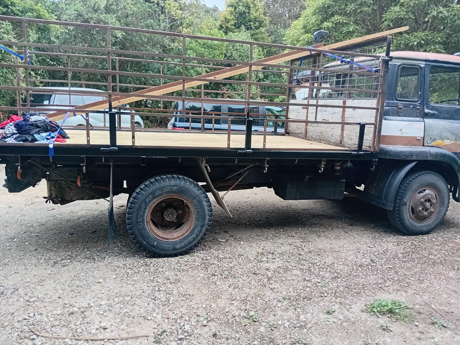
We are tempted and I rang him but no answer. So I sent a text. No answer. I'll try again next time we are over Blenheim way. I think @cubastreet had more luck in getting hold of the fella but he's not after a project. However - I know someone in Dunners who needs a cheap cube and I'm really quite surprised that fella hasn't bought it already.....
-
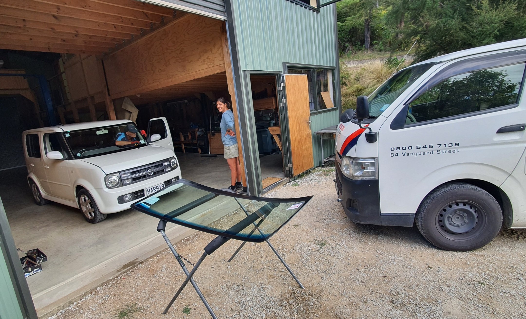
Nice new windscreen today...
-
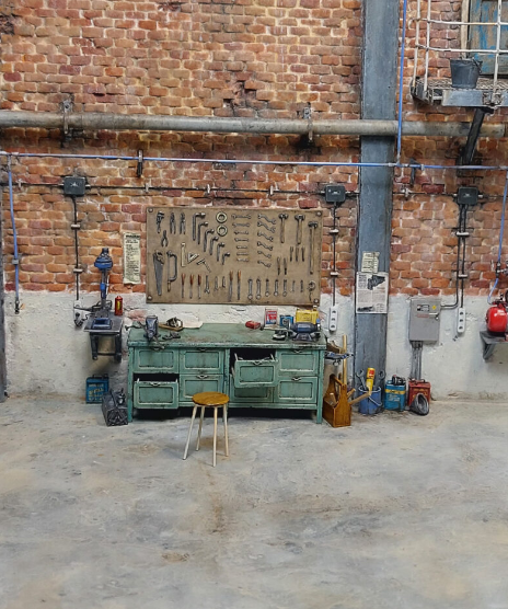
Definitely something fishy going on and I think I've worked out what's happening. Found another picture taken moments before..
-
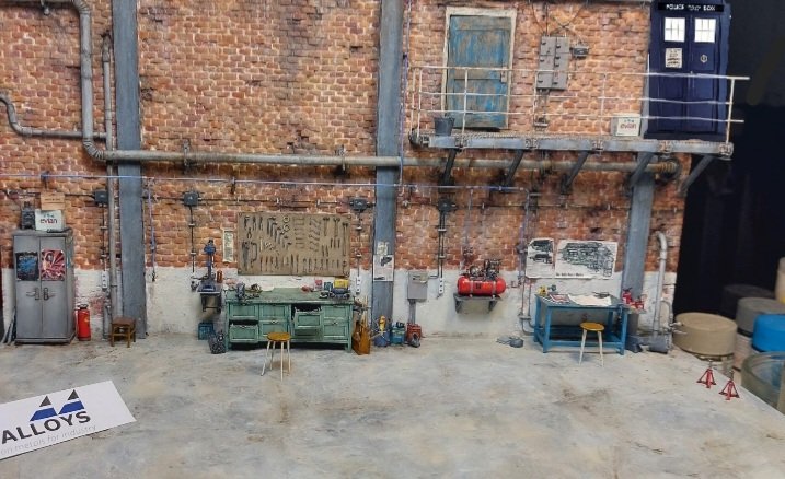
https://www.albionhobbies.com/models/spitfire-diorama-by-norbert-scholte/ Hmmmmmmm Someone has added the radio to throw us!...
-
I'm trying to pick the era that scene is meant to be in. Looks like it could be 40 to 60s until I spotted the stereo on the bench.
-
Discuss here about Yoeddynz's little Imp project...
yoeddynz replied to yoeddynz's topic in Project Discussion
If I'd known all those years ago that Alison Holsts 911 recipe was more far more involved than she'd let on then I'd not have started it. -
Yoeddynzs 1965 Hillman Imp. Chasing Flappy whirrs
yoeddynz replied to yoeddynz's topic in Projects and Build Ups
Exhaust box part two, take one. Chasing a more Porschey sound and also move the outlet to the side for less potential fumes being drawn into the cabin when a window is down. I have been studying various classic and modern 911 silencer boxes and decided I'd do my best at replicating the original design which looks like this... I flipped the design so my outlet would be on the drivers side of the car. Ordered some perforated tube online and bought some 1.2mm stainless sheet. The sheet was polished stuff so I had to get this photo before I cut it up... With my old box removed I cut and folded the stainless, extending it back and down a bit for more volume. Machined up some new flanges to suit the existing inlet pipes.. With those welded in place and the inlets bolted up.. ..I checked the box lined straight with the relief on the rear valance.. At this point I stopped taking photos and just built the thing. I had originally wanted to weld it completely using the Tig but access meant I ended up mig welding the interior panels. I figured that as long as the lowest welds were Tigged in stainless I can hope for a bit more longevity than the rusting out mild steel unit that goes behind the Datsun. One photo I did take was of the partition I had fun drilling out many holes in.. So the finished interior ended up like this... I used all of my graphic skills to make these diagrams to 'show the flow' Old straight through box... New baffle box.. I made some more flanges for the tailpipe. Welded one onto the box, where you can also see one of the exhaust hangers.. 2" stainless tailpipe with flange welded on. I can now easily change the tailpipe in size or shape. Box then got a flick of paint, knowing that I'll no doubt be opening it up to change things.. Started it up. Completely different sound as expected. Much more characterful and classic porsche 911 but a bit hollow. Sounds cool when revved up. Took it for a drive and its much quieter with no load on. At just before 3000 there's a resonance. Then again at 5000. Hard to describe but its like the exhaust pulses are matching and it creates a new timbre, like when two voices harmonise. Its almost comical but not what I want. Hannah took some driveby videos that sort of display the sound... Exhaust box part two, take two... We got home and I pulled the box off and cut a slit along the bottom and added a vertical strengthening plate with a folded over edge to hold its shape. This would stiffen up the base which I think was the cause of some of the tinny thrumming... Took it for a hoon and it sounded odd? Got home , removed the box and realised I had almost covered the inlets. Silly boy! Exhaust box part two, take three. I cut some squares out so I could remove the centre strip obscuring the inlets.. I then I realised was also obstructing flow around the 'holey' partition plate. This time I folded up some stainless into a V shape.. It took ages to tig weld in, starting with many tacks. Its not pretty but I figure it cant be seen easily Splashed some more paint on and took it for a hoon. Its much better but still not what I want. I have more ideas but ran out of time. It was now time to pack up the car and head to Blenheim for the big Hospice classic car car. Some alloy flexy tube had a arrived from Chinaexpress so I finished off the passenger side fresh air vent. It works a treat! Inlet here behind the grill.. We took Kevin along for the weekend. I seemed fine with the new exhaust.. Spent the evening at my mums place giving the imp and engine a good clean. Very shiny.. Car show the following morning. I'd made an information board up because there's just too much to explain to folks looking over the conversion.. The conversion was very popular. Always a crowd looking over it. Really positive response and many people I spoke to really appreciated the info board. I caught up with a lot of old hometown friends, many I had not seen in years. Fantastic weather and good coffee carts! The trip each way went perfectly. Cruised with the flow of traffic, had lots of fun on the twisty hills. Filled the tank for each trip and we were really pleasantly surprised that the flat six returned around 7.5L/100km each way!!! (38mpg in old money) I was expecting maybe getting into the 9s. Its such a good cruiser though - that 5th gear really helps and the torque allows the car to stay in it most of the time when cruising. One of my favourite cars at the show was this little thing... More car photos from the show can be seen here...- 120 replies
-
- 46
-
-
-
But my crayon skills are pretty good it must be said. I can even mix colours and get different shades.
-
Imagine the tiny little pens they must use to write those!!!!
-
Gary has cute little paws.
-
This dude makes some amazing models. Well worth checking out his posts. https://www.instagram.com/reel/DG2zbY5i4N-/?igsh=Y2o3YWlwZnB4MnQ4
-
Ahhhhh ok.