Ned
-
Posts
8,644 -
Joined
-
Last visited
-
Days Won
1
Everything posted by Ned
-
Any chance of moving this a week so it coincides with Felixx being in Auckland? He'll be here wed 25th. Probably no big deal if it's too late, can just have 2 meets
-
it's not? didnt even realise haha. I'm keen for 2 as well, but burger boes is a pretty great thing to witness for out of towners, because its the only time people actually come to meets with some cool cars haha (and if it's a week later, i have SOME chance of getting my car there haha)
-
so i put some parts on! thought i'd share some of the steps for those who find this interesting and are unfamiliar with the process... so first of, you need to design a PCB on the computer, send it away and then PCBs show at your door 2 weeks later like so; Now we have a few options. I could throw dollars around and get a contract manufacturer to put the parts on. They charge about 20c per component to place (as a rough rule of thumb) and then there is a one of charge of ~1500 to get them to setup the machines etc. Very handy when you;re making hundreds/thousands of the same thing, but not when you have to make 1 board to make sure it works first! Option 2, you get friendsly with your soldering iron and you place all the parts one by one and solder them on with the soldering iron. This is how many DIY people do it at home, but this isnt the fastest and doesnt have a very good end result normally as nothing is on straight, and the solder leaves heaps of flux behind etc. Option 3, the option i went with, is spending a little more money, and the man making the PCBs will also make you a stencil. Normally these are grown (yes, grown, it's weird!) but the cheap option is laser cutting them out of thin stainless. What a stencil is, is where there are pads that need solder, they make a hole in the stencil so you can squeegee some solder paste over the top and it leaves solder where you want it, and not where you dont. The other option is using a solder paste dispenser, which is a little syringe driven by air to put some paste where you want it. anywho, solder paste is just that, a paste made of little tiny balls of solder, mixed with some flux. The flux makes it all stick together, and also helps the heat transfer around all the little balls of solder, and when you heat it, it all turns into real solder so after you put some solder on (hard to tell in the photos) we are ready to place some parts! and here is the first part placed! (brown-ish, slightly up from the middle) about an hour later, and all the little passives (caps, resistors etc) are placed! left = done, right = to-do hour 40, and all the bits are on! Notice the tweezers used to place the parts that board is about 65x90mm to give you some size ideas. So before you all ask "why place such small parts on a DIY board?! that seems way too hard!" well, those parts are actually quite big. They are 0805 SMD parts, which means they are 0.08 x 0.05 of an inch in size (2mmx1.25mm) which seems small, but these days people will use 0201 on a regular basis, and even though most get a machine to place them, some still do manual rework on them. Most contract manufacturers dont even have a machne capable of placing 0201s by machine and get done by hand. So 0201 is 1/20th the size on an 0805 the two circled parts are both just a resistor and do the exact same job, just a different size Now that the parts are placed, we get to heat up the whole board at once to reflow the solder and turn the solder paste into real solder and hold the components on properly This is done with a hot plate. Big aluminium plate that gets heated up to 200deg C and then you put the PCB on and solder paste turns into solder right in front of your eyes Sorry about the shit camera work, but heres a video in case you feel like seeing how it works Now just need to put the through hole parts on, and fix the solder bridges etc, and power it up and see if it blows up... (i hate that part... like starting an engine for the first time after a rebuild haha) edit! do they look similar? best thing yet though! it lights up! and the computer enumerates the serial port
- 24 replies
-
- 37
-

-
too late to move burger boes by 1 week chris?
-
just got this delivered!
-
just picked up some more fuel related bits from Tim at TTT Auto Engineering and Segedins. Cost a pretty penny more than expected, but is a lush job, and SHOULD be big enough to feed a 7K
-
china FTW my friend. how bad can it be right? fuel pressure sensor is china also
-
carbs are for suckers! also put a hole in the fuel rail for this So now i have a fuel pressure sensor on the fuel rail to go back to the ECU. Not needed, but i'm going to run a Bosch 044 (china 044) and thats gonna be a little overkill, so going to reduce the flow so want to be able to log the fuel pressure to make sure its not too much for the standard fuel pressure reg, and also enough for when i'm at max fuel etc.
-
Should work now
-
Lame balls! I'll fix it when I'm back in the office
-
Spent the weekend swapping engines //oldschool.co.nz/index.php?/topic/36476-neds-7k-drop-hatch-starlet/?p=1614406 next mission, wiring and plumbing EFI!
-
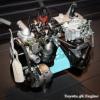
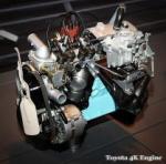
Spent the weekend at Cams working on the car. did this on Saturday and prepped the new 7K to put back in (theres 2 7Ks in this image followed by some fireworks show Then sunday, put new engine in the hole Fuel tank out, ready for EFI conversion didnt actually take any photos of stuff really so not much more to show and then the end of the day, stacked some cars in Cams garage KP is the first and only car to have been on the hoist, and this was the first time cam parked his precious 86 under another car on his hoist. Hope it's still standing! and then today, i received a nice box of bits from DigiKey. 988 little tiny capacitors and resistors etc, so ready for the PCBs to turn up!
- 24 replies
-
- 10
-
-
So the ECU has 6 outputs good enough to do fancy timing for spark or injection. 2 injection and 2 spark and 2 that go to low side switches. Those low side switches can be used to drive a coil if need be, but need some extra hardware (just like a microsquirt) and they may not actually work very well for old style spark? they may have to be logic input like COP or newer LS coils but not sure, havent looked into it that much. The board is being made, i expect that to get shipped today/tomorrow so hope to have it early next week. The parts have already been shipped, so they will arrive monday first thing new motor has been found and am picking that up tomorrow afternoon, and the car is already at Cams where we'll be utilizing his new garage toys this weekend for engine swap Then next week will be make and test board and then do wiring etc weekend after... gonna be fun!
-
Has 2 ignition and 2 fuel with 2 more fuel outputs that need extra drive circuitry to use it. Its really made for 4 cyl batch injection and wasted spark but can do sequential injection if you really want to
-
cheers guys, and no, you just take a punt and hope you're up to the task really. you CAN probably model bits of the circuit in some weird program, but thats only part of it as the layout often has a lot to do with it all and you cant really. Plus i've never used the modeling software so wouldnt even know where to begin haha. you just design a schematic (kinda like a wiring diagram) and then you do the PCB layout and route all the tracks etc. The software will tell you if your PCB matches the schematic and can perform a design rule check, where you can setup things like "i want my tracks to be no closer than 0.15mm from each other" and it will run through and tell you if that all passed.
-
Hey, guys, i did stuff! //oldschool.co.nz/index.php?/topic/36476-neds-7k-drop-hatch-starlet/?p=1609820
-
wow... been a while! Used the car as my daily for 6 months earlier in the year and went fine. Now it's time to actually EFI it though... before drag day (i hope). So i figured, the best way to do that is the hardest way, and thats by designing my own ECU... All i have to design is the hardware, i'll be using FreeEMS to actually run it all, but their current hardware leaves a lot to be desired in my eyes. so let me introduce MicroEMS! a play on words between MicroSquirt and FreeEMS because i made it use the same connector and pinout as the microsquirt, so that if FreeEMS software or my hardware all turns to custard, i can just buy a microsquirt and plug it in a 3D render from the board design program; So i have actually just ordered 10 boards, and am trying to get my digikey account un-frozen so i can order the components for it as well and start building it in a week and a bits time I've been wanting to design an ECU for a LONG time and never really pushed through, but over the last few weeks i've put a lot of hours into designing something and going to finally give it a go. I shall keep you all updated
- 24 replies
-
- 21
-
-
so the funny thing about china, is that they get mega mega good pricing because they make a zillion of 1 product. Meet digikey. This is where a very large portion of hobbyists and professionals get their parts from. Once you get into big volume manufacturing, you would go directly to the manufacturer of each part, but if you have a product that you're making a few hundred or even thousand of, you would buy your stuff from digikey. and this is the digikey link to the micro on that board https://www.digikey.co.nz/product-detail/en/ATMEGA2560-16AU/ATMEGA2560-16AU-ND/735455 spoiler, it's $30 NZ and you can buy a whole arduino for $12 china will sell you the bare chip as well though, $25US for 5 of them, so still $8NZ each http://www.aliexpress.com/item/Free-Shipping-5pcs-lot-ATMEGA2560-16AU-ATMEGA2560-MEGA2560-TQFP-100-IC/1927760663.html?spm=2114.01020208.3.31.jZFqGP&ws_ab_test=searchweb201556_2_71_72_73_74_75,searchweb201527_4,searchweb201560_9 It's crazy at how cheap they churn those out. If you were to make them in NZ (or any other place in the world that isnt china) then just the cost of putting the components on the PCB would be more than what china sells the whole thing for. And thats not even buying the bare PCBs or the parts for the board. Thats just the cost for a machine to place them on the PCB and solder them on. It's crazy how they can do it, it really is...
-
i'm sure the ones that care are actually on the speeduino forum, but the man did some actual tests on timing accuracy (on the bench) and here are the results, they are pretty good (for a low burget DIY EMS) and a lot better than most documentation on the web makes it out to be (which is where my initial info came from) http://speeduino.com/forum/viewtopic.php?f=5&t=223&p=2955#p2955
-
So micro is short for microcontroller, which is the processor. (sometimes can get referred to as uC to shorten it some more) Arduino has lots of different boards with different micros on it depending on how many pins you need, or what size memory etc etc. The one used for speeduino is the biggest, baddest one they have. All of them, share the same arrangement for how the connectors come out of them, and you can plug in things called shields. A shield is just some extra hardware you can simply plug in, and sometimes even stack lots of them together. So if you want to add ethernet to an arduino, you plug in the ethernet shield. If you want to control some servo motors, you add in that correct shield etc. Speeduino is essentially just an engine management shield that you plug in to give it the hardware it needs to run an engine. Nice and easy for development, not very robust for real life applications. People use arduinos for 2 reasons really. 1) arduinos have a very simplified coding overlay provided for them. So hobbyists dont need to learn an aweful lot about software and hardware because it's all standardised and simplified. You can just about say "turn on pin 1" and in the background it goes and figures out what pin is pin 1, find the correct register for that ports data direction pin, set it as an out put and then find the right register that controls the state of the pin and then set that high. It's like driving an auto vs a manual car kinda. You dont have to use the simplified software, so people like me will use an arduino as a set of building blocks. I will get an arduino, find a shield with some bit of kit i want to use in a project and then i can just plug it in and evaluate my design, get testing etc and if i like it, i can go and build some dedicated hardware where everything is just on one board. This is what speeduino is kinda doing, but they arent making the leap to dedicated hardware yet and i'm not 100% sure why they havent yet. They might have a good reason i havent found yet.
-
Whats wrong with this? https://www.autosportlabs.com/product/racecapturepro/
-
Fred? He doesnt like tunerstudio and wants to do his own thing, but that hasnt happened yet. Tuner studio has some limitations etc and apparently isnt unlikely for it to do the wrong thing. I have no idea and dont know anything about that side. The more and more i'm thinking about it, the more and more keen i am to just redo my board for speeduino haha, but a dedicated board, none of this arduino shield stuff. I mean those are the micros i cut my teeth on at work, and know them like the back of my hand so software development would be much easier for me and i could actually tune my car if i changed haha
-
Now look what you've done Alex! I havent made them yet, finishing touches ATM and sending off this weekend so will have them in a week or 2 probably. In time to run the KP for drag day i hope and i've jumped on the forum, i had a look around at the schematics and they seem to be very stongly influenced by the FreeEMS ones. A lot of similarities there, which is cool. Means that other than the micro, there isnt much different hardware wise between my board and theirs because mine is also strongly influenced by FreeEMS (because it has to be) so if my thing works, it would be easy to spin up a slightly different board with the same interfacing hardware, just a different micro/brain so that i can run his code, as it seems more complete than FreeEMS...
-
im sad i only just found out about this
-
It's not as exciting as it looks in fairness. I need an ECU for the starlet, and with the exchange rate, buying a microsquirt is too spendy, so for the price of getting just the loom shipped to my door, i can build a whole ECU. It's based on the FreeEMS stuff Fred wrote/is writing but is pin compatible with microsquirt, so if i ever get sick of it or if my design is rubbish, i can just plug a microsquirt in and use that haha. So same as microsquirt, 2 fuel, 2 spark, 4 spare low side drives. Some analogue inputs, 2 VR/HAL inputs. Has USB on board too, which is the only real difference functionality wise. FreeEMS is definitely not ready for this to be a thing lots of people use. It currently has no good way to tune it, which is the main down side of it all but i'm happy to make do with whats there (for now anyway) for me its as much an exercise in designing the thing as it is having an end product so even if its shit, i'm still happy.