

Hurmeez
-
Posts
341 -
Joined
-
Last visited
-
Days Won
1
Everything posted by Hurmeez
-
So the weekend came and went and made me a very happy boy! We left Whangas at around 0730 Saturday morning and got into the wreckers at 1030. I wanted to get in as early as possible to try to get the most amount of daylight possible, as well as beat any other prospecting V6 removalists to my prize. It took us three hours, but we got from this: To this: We spent the next hour or so stripping all the unnecessary ancillaries like AC and power steering pump off before slotting it into the back of the car and coming home. It turned out to be a very good thing we got there as early as we did because as we had it hanging and were stripping it down, some poor bugger came to find a big empty hole where he thought his engine should be. We helped him out with a belt tensioner and other things I already had at home but there were a couple of things he said he'd been planning to grab that we already had our hot little hands on. Yay for planning ahead. Tonight I spent an hour playing around with different bits and pieces to see what I'm dealing with. @yoeddynz, you were dead right about the right head, wrong gasket guess. Ironically, my DE from last year had the opposite, wrong heads, right gasket and intake manifold. Huh. Those sweet, sweet KL31 cams. While I was down there, I also picked up a cam cover from a 2.5L Telstar. I thought it would suit the car a little better and help me say, "it's only the DE bro, honest" before I blow their doors off And here it is fitted I also started to have a look at my flywheel options. I bought an RX-8 flywheel a long time ago before I realised how difficult it would be to adapt it to work on the V6. I pulled it out tonight to see how different the two were, and what the best plan of action would be. As you can see in the photo, the RX-8 flywheel on the right is 35mm larger in diameter than the V6. It's also lighter interestingly so go figure. The two friction disks are the same diameter at I believe 225mm (though that's just from memory), however, the internal splines on the V6 are smaller so it doesn't fit the RX-8 input shaft. The spigot bearing diameters are the same though so I was able to fit the V6 fly to the RX-8 shaft to see how far out the starter was. The answer is "quite". I should have used the flash but never mind. As you can imagine, that 17.5mm difference in radii makes for quite the gap. It would be a hell of a mission to move the starter location so the plan right now is to modify the flywheel. My original plan was to order a custom machined one from the tame machinist down the road (the same guy who milled the aluminium intake I made for the old Pinto), but I think we have come up with a better idea. It should be much easier (read cheaper) to remove the ring gear from the V6 flywheel, then machine a ring that has an undersized internal diameter and heat it to shrink fit over the original ring gear surface of the flywheel. Then, re-machine it to the standard RX-8 flywheel outer diameter before shrink fitting a new RX-8 ring gear over the top. Then I'll have to machine a spacer for the crankshaft but that should be the easy part. I'm wondering whether it would be worth machining down the back side of the flywheel while I'm there to lose a few kilos for that extra zingy V6 feel. How does the plan sound to you guys, both from a safety, and rotating assembly balance standpoint? Let me know your thoughts on the matter.
-
Not really. I'm a tradesman's assistant doing fitting work. Essentially I'm doing all the same stuff as the 30 year veterans but their experience means they're being paid twice as much.
-
Yeah being an unqualified school leaver, I'm doing the stupid hours bit but not so much the stupid money bit. Still, it pays for more car parts so I'm happy.
-
Bingo mate. I'm gonna have to be more careful, you guys are going to work out my secret identity!
-
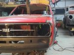
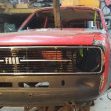
So I've been working 70 hour weeks for the last month and a half, meaning not a huge amount of fabrication had been happening for a little while. Rest assured though, there has been progress and I'll do a proper long winded update soon. For now though, I need to ask a couple of favours. Firstly, I did end up acquiring the R31 diff housing and axles. However, as I mentioned previously, I'll need to get it shortened to fit. Can anyone recommend somewhere to get this done? Bearing in mind I live in Whangarei so I'd prefer it to be no further south than Jaffaville. I plan to strip the whole thing down myself to the bare axle and weld on the spring perches once the work is complete so all I need done is the physical shortening of the housing and axles themselves. Any help would be greatly appreciated as per usual. Secondly, by extremely exciting happenstance, I stumbled across a bona fide KL-ZE in a wreckers in Auckland! (Excuse the blurry photos, it was pissing down and I wanted to make like a shepherd.) Since I don't want to let this opportunity slip through my fingers again, I'm planning on going down with a mate on Saturday morning to pull it out and bring it home. If anyone would like to come in, help out, and spin a few yarns at any point during the day, we'll be at the Zebra yard in Wiri for most likely the whole day. Let me know by private message or on here if you have any advice or are able to help out: Here's to less month long blackouts.
-
Yeah and me
-
That's weird cause I measured it roughly with a ruler after you said and it looks like the pitch is 1.25 to me. I counted ten threads and it was 12.5 mm on the rule so I would think that means 1.25. In any case, I haven't ordered the bolts yet so no big deal. Thanks for chasing me up though.
-
Yeah I was having issues with that one too but I came up with what I think is a very cunning work-around. All will be revealed in good time
-
Brilliant! That's exactly what I needed. As I said, absolute legends
-
Yeah that was my plan to use the bolts from the back too. Thanks for checking.
-
A quick update not big enough for the main thread. I'm working 13 ten hour days in a row with one day off for a couple of months so I'm not getting heaps of work done, however, I am getting closer to getting my adapter plate finalised after not worrying about it for a good while. However, I'm hitting a problem. I can't get countersunk bolts to fit the V6 bellhousing from any of my local suppliers and I'm struggling to find any online. @yoeddynz , @Transom, you guys don't happen to remember either where you got yours from, or the size and pitch of the bolts so I can hopefully better my google-fu? You'd be even more legendary if you could. Also exciting developments on the diff situation but I'll leave that for a full update later on .
-
How much did you actually shorten it by? I'm trying to find the R31s width online but I'm finding anywhere from 1410mm to 1470mm so I'm not completely sure how much it will need cutting.
-
I suppose that would be an option but I think I may run into an issue with the bearing retainer access holes. I probably could fit another stud in there in between the two but I'd be worried about how close it would be and the strength (or lack thereof) it might have. I don't think you are allowed to weld up the holes because it screws the heat treatment right?
-
I finally got around to putting in the brace between the chassis rail and the firewall on the passenger's side. I did the driver's side ages ago but for some reason, I always found something else to do until now. I'm happier with this side. It turned out better than the first try. Next, I started working on the rear engine mounts (also known as gearbox mounts). I figured since I don't have my adapter plate yet, I can't make the front engine mounts. Without it I can't be certain of where the engine and gearbox sit relative to each other so any mounts I make with my makeshift MDF plate may not line up properly when it put the steel one in. However, I can make the gearbox mounts because I do know where that will sit relative to the hole in the tunnel. So that was my next move. I used the Turbo Yoda method to hang the gearbox while I built the mount for it. This lets me hang around underneath the box as much as I want without running into something holding it up from the bottom. Also, thanks to the threads, I could raise or lower the box as much as I wanted with plenty of precision to align everything properly. I set the angle of the engine to be the same as the stock crossflow in dad's car. This means I don't have to worry about the driveshaft angles being out on the U-joints. From here on the photos start to get a bit spotty because I just had my head down and completely forgot to take enough photos. Oh well. Anyway, I started but making a mount to pick up the points used to mount the black bit below the output shaft in this photo: (That's not my photo because I forgot) It is some sort of steel block rubber mounted to the trans but not mounted to anything else. Possibly some sort of vibration dampener. Who knows. Anyway, I used it as a template to make a similar plate out of 5 or 6mm steel plate (I forget which), which also has mounting points for an off the shelf mount. Something like this: I reused the press in studs from the original mount but cut the tops off and welded them in with lots and lots of amps on the TIG. Then I made it pretty. I used captive nuts rather than tapping the plate, mostly because we only have a bottom tap in the pitch I want and I couldn't get the bastard to start. So nuts it is. What are the nuts for you ask? They bolt to an off the shelf, out of focus powerglide trans mount like this: It's nice and low profile (and cheap) and will fit really well. Here is the whole assembly in place. Next I started on the car side of the mounts. I wanted to more or less copy the design that the factory used. These are a couple of boxes that are welded to the tunnel with some tapped doubler plates behind the mounting surface. The advantage of doing it this way is that there are no penetrations in the floor, so fewer opportunities for water to enter and start causing rust. Also, bolts sticking through the floor just suck in general. So it started with a cardboard template to get the shape right, then I started to transfer it to some 2mm sheet (the same as the factory mounts). Then I made the doubler plate out of 10mm plate. I managed to get the tap to start this time so I made a real nice job of them. Then I welded them in place. This was great fun because it was the hottest I've ever run the welder and laying the fillets in there just felt fantastic. Finally, I fully welded the seams and bent the flanges over. This is it compared to the original. Pretty good I reckon. Then I tacked them in and completely forgot to take any photos. Yay!! I'm planning on putting the car on a rotisserie to stitch weld the chassis rails so I'll fully weld them then. For now though, I'll just leave them tacked; I really hate welding on my back. Finally after all that, I started on the crossmember itself. Starting with a cardboard template in terrible lighting. Of course. Then I started to transfer it to a piece of box section I picked out which happened to fit the powerglide mount spot on. And then I forgot to take photos while I cut it out and bent it to shape. In any case, take my word for it that I did. And here it how it turned out: You'll notice the gearbox looks a bit crooked. It is actually clocked approximately 2.5 degrees clockwise relative to the car from this perspective, and offset to the passenger's side by about 10mm, all for a very good reason. I'll go into that later on. I still need to cut some of the green off the ends, drill the powerglide mount holes, and finish weld the joins. Other than that, it's pretty good. It's 3mm plate so I don't think it will need gussets between the bottom and the mounting flanges, though I might do it anyway later on. We'll see. In other news, I've been looking into diff upgrade options for a while now and I think I may have come across a very viable deal. I was lookinginto a hilux diff, but they proved to be harder to find than I expected. They also don't seem to have many options for decent crusing ratios, as well as options to easily (read cheaply) convert to four stud, which I really want to keep for my Cheviot Turbos. So instead what I've found is an R31 Skyline diff nearby for $150. I saw that @Rhubarb77 had used one in his turbo Pinto MkII so I know it can be shortened to fit and will obviously hold over 300hp easily (which might be part of future plans). It's four stud already, and I can get a bolt in LSD 3.54:1 center section from the wreckers down the road for another $150 or so. Those are the positives. The negatives are as follows: It has no brakes at the moment, disks or calipers, and the stud pattern is 4x114.8 rather than my mag's 4x10⁸. I have thought that I could put the rears in a mill and slot the holes slightly to fit but I don't know how well that would work. Does anyone else have any experience in this sort of area? Should I pull the trigger and buy the diff or do I have better options? Let me hear your suggestions or comments here: Cheers
-
Yeah they are Prelude seats. I'm not a massive fan of the weird headrest setup they have but I have a plan for that and they were free, so I can't complain.
-
Brilliant. Gotta love bureaucracy don't you?
-
Now that the tunnel was finalised I could finally get to welding in the seat mounting boxes. You'll recall way back in October of 2016 I folded up some channels and made them fit in place of the old seat boxes. Something like this: I held off welding them in at the time because I thought I would have to get a cert man to come and have a look at them before I could. It turns out a simple email with photos was enough to make him happy but in retrospect, I am very happy I held off. If I had welded them in it would have been a nightmare doing the tunnel modifications. As it was, it was still a bit of a mish but that made it a lot easier. Now though, the profile on the inside end of each box doesn't fit the new tunnel, so I had to modify them to make them fit the new tunnel shape. That done, I wire-brushed and thoroughly cleaned the floor that would be underneath the box, as well as the underside of the box itself, then painted both with a couple of coats of Hammerite. I made sure the steel directly underneath where I was going to weld had no paint on it before I went around the edges with some weld through primer. That done, I got it tacked in place and checked the fit with the seat. Happy with that, I marked and tacked where I wanted each stitch weld to go, then fully welded it in. Meanwhile I had been doing all the same processes to the rear seat mounts too: They shouldn't be going anywhere soon. Then it was a case of repeating everything once more on the other side. I think I'm finally getting the hang of the MIG now too. I made some pretty good looking welds on these bits; one I'm particularly proud of: Pretty shit photo but you get the idea. Then, of course, it would be rude not to bolt the seats in and make broom broom noises. While I was in there I mocked the rear seat up to see how it would fit with the new seats. With both seats at the back of their travels, this is the leg room you get in the back. Doesn't look too bad. Nevermind, it sucks ass. It probably wouldn't be too bad for short trips but bugger driving to Auckland like that. Oh well, I'm not going to be sitting back there so who cares? Also had a bit of a premonition. Look how much crap you can fit in the back! After sitting in it for a while, I couldn't help myself and just had to bolt the door on to hang my arm out the window. Note my false ground level with the bucket and wood. Feels pretty good to get into and out of. Now I can start working on engine mounts or something. It's all feeling a lot closer now.
-
I always seem to read back over my previous post and find that I mention something about finishing something in the next few days. Then I check the date and realise it was over a month ago. Woops. Not long after I posted the last update I had to take two weeks to turn this: Into this: Some muppet (me) ran out of talent on a wet intersection and made an adjustment to a nearby fence. So I spent a while sorting all that out before finally getting back to what matters. Picking back up on the brace, I used some paper to make templates of the large flat panels that Would be needed to weld it all to the floor. I can't believe it has taken me this long to figure out that using magnets instead of tape in these situations is such a good idea, but, there you go. Then it's the standard procedure of tracing that onto steel and gluing it all together. And offer it up to check the fit. The camera angle makes it look a bit crooked but it's pretty good in reality. I gave all the welds a good clean up then coated it in a couple of good thick layers of Hammerite. I initially intended to use POR15 for this but the local shop has stopped supplying it for whatever reason and the guy said this was just as gooder so I figured it's better than nothing. Here's a comparison shot between the factory brace and my version. Note that I sprayed weld through primer everywhere that it was appropriate in addition to the heavy duty rust preventative. I've had issues in the past with this particular primer making for a spitty farty weld, so I cleaned off all the actual spots where the welds would be. As it turns out, I probably didn't need to but it did make for a lovely weld. Which you can marvel at here: It really was such a nice change to be welding good new steel to steel rather than burning holes in thin factory stuff all the time. And with that, I am finally back to where I was five months ago. Well with a much larger tunnel now but you get what I mean.
-
Brocky41's 1963 Ford Cortina MK1 - Discussion
Hurmeez replied to brocky41's topic in Project Discussion
Very cool car man. I'm glad you're leaving it as is for now, it looks perfect just the way it is. -
Discuss here about Yoeddynz's little Imp project...
Hurmeez replied to yoeddynz's topic in Project Discussion
Yeah makes sense. The hardest but for me is as soon as it makes any sort of hole it just instantly runs away on you and turns to shit. Then it's all about trying to fill holes in old thin English tin and that's never fun. -
The bug is looking sweet man. BTW, not sure how long you've had that link in there but you're a godsend for showing me the photobucket fix chrome extension. It saves so much frustration. Legend.
-
Discuss here about Yoeddynz's little Imp project...
Hurmeez replied to yoeddynz's topic in Project Discussion
I always have a hard time butt welding new steel to old with the MIG. Hat's off to you sir for making it look so easy and clean. -
This unemployment malarky can have some benefits... In my ample free time, I got the ring fully welded in, cleaned back, and dressed in a quick coat of PA-10. Like a bought one. Next, I wanted to replace the tunnel brace that ties the two seat boxes together and stiffens everything up. Something like this: I thought about integrating this into the driveshaft hoop and making it out of some 6mm plate that was folded to shape. Then I could have some captive nuts under the seat boxes and bolt the bottom half up to it around the driveshaft. It would be plenty stiff enough to brace it properly, as well as fulfill the minimum specs for a driveshaft hoop, killing two birds with one stone. However, I decided that where I wanted to put this brace was too far forward to meet the requirements for a hoop and thus I opted to make one that emulated the original factory design with a separate hoop further down. So I set to with the CAD, and started to design my interpretation of a Mk2 Escort Estate trans tunnel brace to fit a modified tunnel designed around a Mazda KL-ZE mated to a five-speed RX-8 gearbox. Simples... This is what I came up with: I modeled the top and the passenger side initially because the tunnel is more or less symmetrical. And cardboard is too boring to waste too much time on. Then I said the magic words and...Poof! This popped out. Then came lots of fitting and removing and fiddling and refitting until I got everything exactly where I wanted it. Now it was looking right but it wasn't going to be doing a lot of bracing in its current state. The lack of corners left it really floppy. So I fixed that: I started with the flat bands across the top which immediately stiffened the whole thing up considerably. I also added the oval shaped hole in the top to match the original while I was there. I'm not sure exactly what it's for but it looks right now. Then I added the corner pieces and cleaned everything back. This left it looking properly profesh. And what's more, it fits! I threw the motor and box back in there quickly to check the clearances for that too. Miles of space there so I'm perfectly happy. The last thing I'd want is to spend all this time on it only to find it fouls the box. It's funny, looking at it now, I probably could have done my driveshaft loop idea after all. It is probably sitting right over or slightly behind the U-joint, which would be perfect, but oh well. I kind of like the OE spec solution I've come up with here. Next, I'm going to weld on the big pads that get rosette welded to the floor under the seat boxes, and finally weld the whole lot in. Hopefully, with a bit better focus, I can get that and other things done in the next couple of days. I've also been every now and again checking the wreckers websites and Trade Me and so on looking for a genuine KL-ZE motor, but still no luck so far. There was a promising looking motor down in Christchurch but it had the wrong cams and unknown heads. It would have been quite a bit of money including shipping and for that, I would want to be absolutely sure of the specs, so no dice. C'est la vie. The search continues...
-
I got gas! (Seriously ask my girlfriend, she'll confirm) So I set about finishing up the other side of the tunnel. So there you go. I didn't measure it exactly but my estimate is that it was about one and a half metric ass loads of one-inch TIG weld stitches in total but there it is. All welded in. Next, I wanted to make a flared ring around the gearbox hole--like the stock Escort tunnel--to attach the shifter boot to. I started by measuring the one off my old tunnel and cutting a strip of steel the same length as the circumference of the old hole. Then I loosely formed it into a ring, And clamped it up with a hose clamp. Then I tacked it, removed the clamp, and fully welded it. I gave it a quick clean back, Then rolled the top and bottom edges over slowly with a pair of pliers, making small tweaks and working my way around over and over until it was this shape: I gave it a quick tickle with a hammer over a dolly to smooth it all out, then traced around it and opened the hole in the tunnel out to the right size. It was tacked in before I threw the engine and box back into place to check how it is all going to sit. Bearing in mind that the engine and box are only sitting roughly in place, I'm very happy with where it has all ended up. You can see there is plenty of room for the engine and box to move if the mounts get a bit sad, though I'm planning on making them fairly stiff so that should never happen. The boot also fits really nicely over the rim as you can see here: The bottom part of the rubber is turned up so you can see the sealing ring properly. And this is how it will look in the finished car: I took a quick snap of dad's stock shifter and handbrake and you can see that my setup hasn't moved the stick back that far at all. Far less than a Type 9 would have at the very least. In fact, I measured it and it is only about 40mm rear of the stock position. That's more than good enough for the girls I go out with. Next job is to fully weld the ring on, then onto other exciting things.
-
Bloody hell! Two and a half months sure does rocket past when you're not paying attention! I finally got back into the car in the last week or two after doing a couple of months work experience and coming home with absolutely no energy. That's finished now though so I can afford to really throw myself back into the car. I've started back in by making a really decent push to get the tunnel fabrication sorted. I found that with the current profile the clutch fork and slave cylinder would still foul on the tunnel so I decided to take it from the semi-circular shape I had it at and roll the flange further along to make a more traditional rounded square profile. From this: To something more like this: But that presented a new problem. Now I had to make the tunnel fit the new shape and I didn't want to cut it at all if I could possibly avoid it. So, out came a BFH and a sandbag. I started to form a bulge that would transition the rounder profile of the rear part of the tunnel to the squarer corners it would need at the front to clear the clutch bits. Once I was satisfied it would clear everything, I called in the big guns to help form a matching bulge on the other side, purely because it would look weird otherwise. Which gave me a nice pair of firm, perky, erm, bulges. Or Tolerance Improving Tumor Shapes (T.I.T.S. for short.)You can also see here the relief I pounded down just below the T.I.T.S which is designed to allow me to use the stock heater unit, something I would very much like to do. Once I had the right shapes hammered in, I offered it up to the hole in the floor and clamped it in place. Then I sprayed some paint around the overlap points to show me when I needed to cut off material. You may also notice that the rear part of the tunnel doesn't really fit anything very well. My next step was to remedy that. I started by making some slits which allowed the sides to move in the right amount to fit the width of the existing tunnel.Then I welded it into this new shape and offered it up once more. Looking much better. Next, I needed to make a piece that would bridge the final gap between old and new. I pushed some paper up into the underside of the two sides and taped it in place. Then I used the rattle can again to show me where the edges of the paper template would be. Then transferred to steel, formed, and welded on. Cleaned back and painted, And finally offered up once more and tacked into place. At which point I set to and slowly started stitching it in. Originally I planned to spot it in with the MIG but it was turning into a nightmare so I returned to the TIG. I found the heat much easier to control this way and managed to produce a much nicer finished product than the MIG. It came out quite well with much less warping than I expected. A tickle up with a hammer and dolly and it should be mint. I gave it a quick linish back with my new hand linisher and a lick of paint to stop any surface rust from starting. I'll finish the other side tomorrow when I get some more gas. For now though, that's it. Thank you and goodnight.


