

Hyperblade
-
Posts
439 -
Joined
-
Last visited
Posts posted by Hyperblade
-
-
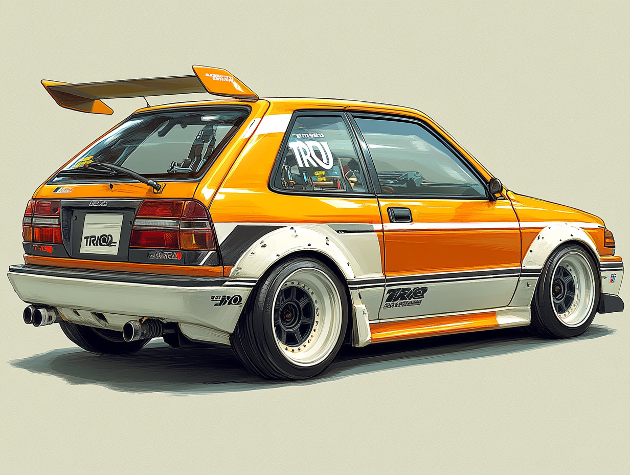
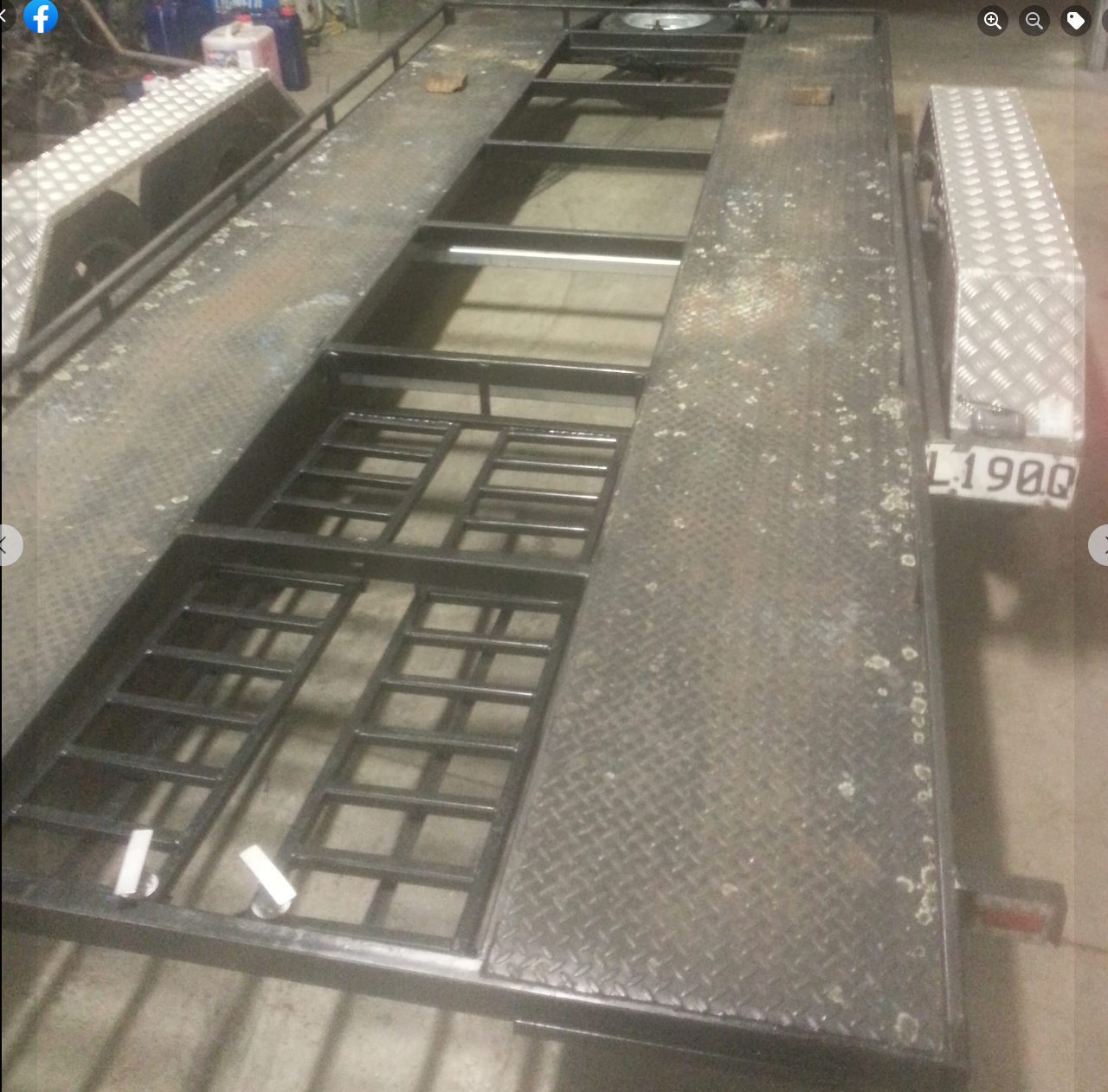
Car Trailer (L190Q) and Honda FN2 Racecar (Still stickered from 24hr race) were stolen last night.
They were last seen (after 5:45pm) being towed by light or champagne colored Hilux Surf (no lights on) going past Hellers
$2000 reward for complete return.
PM me if you have any sightings of it.

-
 9
9
-
-
15 hours ago, kpr said:
one word -> packaging
they will be aiming for the 3rd harmonic (itb's, the skunk2 maybe even 4th) im aiming for the 2nd, which is stronger = more power
tapered is said to accelerate the air. maybe. but are also losses in the pipe, so need to go bigger further from head to keep flow the same as. real world isn't much effective length difference with taper, unless is way too much. or turns into a massive bell mouth, which will act like the pipe ends part way down the bellmouth into the runner, rather than the face. in your case yeah i would taper out soon as get past the throttle plate.
Example of engine not caring too much if runners are too big; The runners on the manifold i made are 2.25" tube. think its 53 or 54mm id. half way around the bend it starts tapering down to the port. so yeah its big. bigger than the rbc intake and huge compared to the stock k24 manifold. but still gains power right down at 4000rpm. close to 10% at that point, so not a small gain either.
Another example. The only place my 4age with 52mm throttles drops below a stock engine is under 2000rpm.
Ahh that would make logical sense.
I'm not sure Skunk2 were aiming for any harmonic it looks more like it's designed for turbos.
320mm long looks close to a lot of things, may have to curve the velocity stacks to fit that in but that's all doable if being 3d printed. Will be another learning experience.
Thanks for the feedback!
-
5 hours ago, Roman said:
Hey I've got a standard S1000RR airbox - but I bought the wrong one.
It didnt quite fit because it must be the box for the slightly different variation of throttles from the earlier or later ones.
However it was definitely interesting to look at the mechanism for how it adjusts trumpet length, and the injector positions.
My consensus was that it was interesting to look at, but I dont think it would have added enough benefit for a car engine to be worth buying another one that fit correctly when adding to a car engine.
What I mean is, the box has shorter runners for higher rpm. But those bikes run to 14,000rpm so "low" rpm might be below 10k haha.
It's got a massive span of rpm it needs to operate compared to a car engine, which is why I think the dual length runner was valuable.
Also why the outer injectors earned their keep.
It was also interesting that the position of the outer injectors was so incredibly far from the runners, when the upper trumpets were lifted up for high rpm.
It must have essentially just been fogging the whole airbox. Like maybe... 150mm away from start of the bellmouth.
I will take some pictures and measurements when I'm next over where it is.
Can send it to your for cost of post if you're interested but it wont fit.
Those are good points about dealing with the rev range. I've looked at the videos of how it works and it is a very clever design in it's simplicity.
Still want to try it just to see the impact, I'm trying to get everything out of a stock K20 without opening it, so every little bit counts!
3 hours ago, kpr said:Yup, thats the same inlet test i was referring to.
Have you looked into s65 bmw throttles? they are 52mm, spacing should be pretty close for k series. the also have an oval outlet similar shape to the port. Have a separate dbw module that can be used if wanted to go that way. but is known to crap out.
I'd probably target 8000rpm maybe a touch under for your intake runner length. about 320mm from port face should get you ballpark. you want to get the intake tuning right where the engine naturally wants to make peak power. will make more power and fatten it up that way. rather than kinda trying to force it to make more power right up top. like your current intake looks to be doing. The VCT (cam timing) is also your friend here. you can use it to hang onto the power past peak a bit longer. If do everything right it should at least match the power it has now right up top 8500- 9k and make a bunch more 7500- 8000rpm plus more through the mid range
The runner length on the manifold in video is around the 350mm mark, as was targeting bit lower rpm.
Skunk 2 Ultra Street Manifold Runners
Just measured the Skunk 2 Ultra street Manifold runners as a data point.
These are all rough measurements as it's still on car and I'm not taking it off as it's a full days job (one of the reasons why I want to go to ITB's).
Runner length 155mm from port face to velocity stack tip (estimated)
Outer diameter where runner goes into manifold is 60.50mm, I think there is a fair bit of wall thickness assume 5mm which would make 50.50mm inside diameter.
S65 ITB's
S65 ITB's are out of my price range at the moment, plus the ones I have are a seriously nice bit of kit in terms of packaging and weight. I'm happy to use these ones to get experience with them, if they work better then what I have then that means I can sell the old skunk2 setup and look at other options. Will only cost me the ITB's and filament which is not a lot in comparison to off the shelf ITB's, plus i'm now sold on electronic ITB's since i've spent time and wired for them (obviously can still run cable if I need to), but not a chance I'm going with dbw module that's know to crap out...
I had looked at the efi hardware ones back when i was first looking for options, but they add up quickly with all the linkage and accessories needed.
Runner Length
So in terms of runner length for the Jenvey ITB's (EP3 version BUT NOT the Tegiwa compromised version) they look to me
Runner - ITB - Velocity Stacks = Total
85mm - 66mm(tapered) - 90mm(tapered) = 241mm
So I was planning to match that with
85mm - 78mm(tapered) - 78mm(tapered) = 241mm
But based on your suggestion it would be
85mm - 78mm(tapered) - 157mm = 320mm
So it's interesting to see such a big difference between your suggestion and theirs!
How does a tapered velocity stack affect things, my thinking is that as it's expanding it's slowing the pressure waves, so making it behave as if it's a longer velocity stack? How do you calculate that effect into it?
-
19 hours ago, Roman said:
Okay soooo
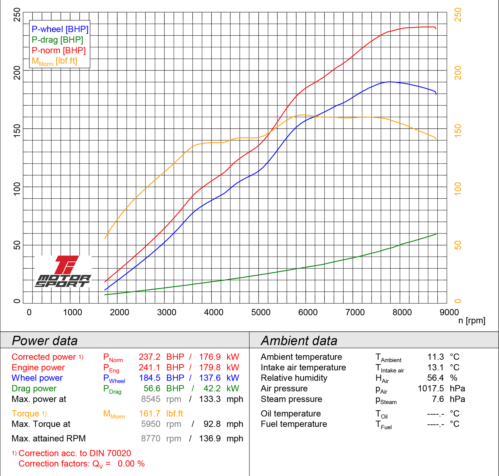
They had 184.5 wheel horsepower.
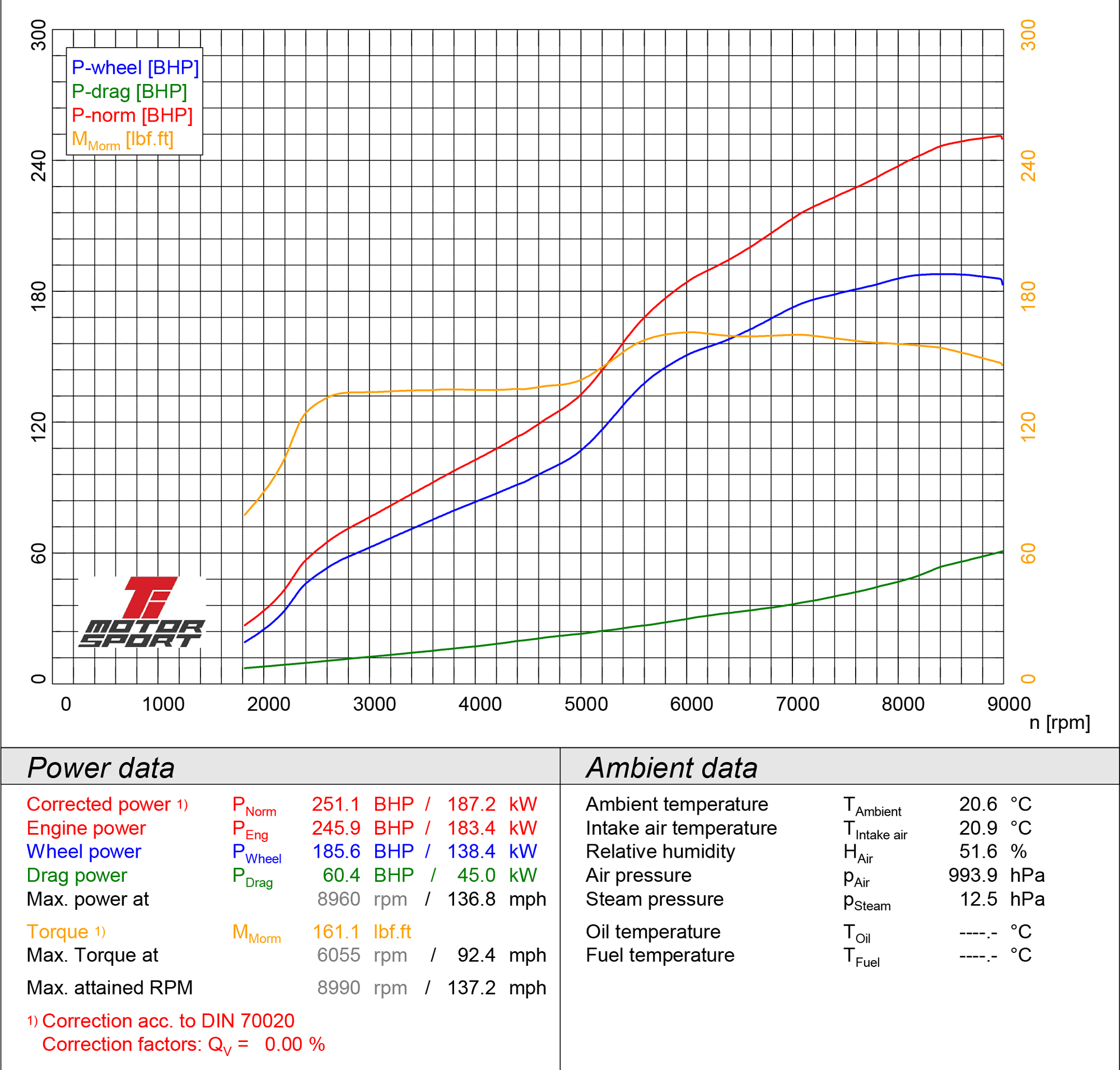
Then fitted ITB, and now they have 185.6 wheel horsepower.
So a 1.1 horsepower gain in real life.
But they now for some reason have 60.4 horsepower drivetrain loss instead of 56.6 horsepower drivetrain loss.
Did someone pour sand in the gearbox when doing ITB swap? haha.
This is why I hate "at engine" power figures.You have to love the drivetrain loss going up just at the end of the graph to produce a nice curve, very convenient for them...
To be fair the ambient temperature was different on the day.
But yeah, people need to stop with BS made up figures.
16 hours ago, kpr said:As above, I have been looking at some of the stuff they post. as been playing with a k24. They quote all these different gains in bhp, but the wheel hp on the same graph says something different. also mega driveline losses. Ive roughly overlaid the graphs blue is the wheel hp. red "engine" power. light lines stock intake, dark itb.
Looking at the wheel power. the stock intake manifold would be a quicker car. unless you could run between 8000 & 9000 rpm the whole time. even then wouldnt be anything in it.
Why, The itb's will probably flow more. but the runners are way to short to make any jam over the whole rev range. stock inlet will be running out of flow and or slightly too long to make power at 9k
ITB's only work good if you dial in the runner length and have the flow to go with it.
Seems to be super common with K series stuff. even the factory inlets. They are too short with big runners. or long with small runners.
I think those itb's you have will be a touch on the small side. possibly ok. but can get away with over sizing the intake a bit. not so much under sizing it. if make the runners small enough to gain in the bottom end (talking rpm you will never use in circuit car) will lose top end. if a bit too big, not much happens. not trying to lecture you, just wouldn't be fun to have to do it twice if you didn't have to.This is the intake i just made for k24. Big long runners. gains everywhere over RBC honda inlet. which is spose to make more peak power that the stock ep3 one they compared the itbs too.
Yep, here's another brilliant one from them, I'm sure you've already looked at it.
https://www.tegiwaimports.com/blog/?p=2443
I got caught out by this one when I brought my current ultra street manifold, i'm much more careful looking at these things now.
Lecture away! (happy for anyone too), I always like considering all the possibilities and discussing this stuff with people who have actual real world experience.
I agree slightly larger ITB's would be ideal so that you have a bit of wiggle room, but the feedback I've had is the normal Jenvey ITB's worked the best on a dyno(on built k20 in CRX) when comparing multiple different types, so if i match them in design I'm confident that it should perform at least better than the skunk2 intake I have currently.
But I'm limited by what you can easily get off motorbikes due to the pricing, I had a look around at other options, but nothing stood out.
However I do have a couple of other things planned to throw into the mix.
- Outboard injection.
- Variable velocity stacks (I'm on the hunt for a standard S1000RR airbox to get the mechanism)
- Intake will be using ram air to create pressure through filter and into air box.
- I have heaps of room to play around with lengths of stacks (which will be 3d printed so not expensive to make).
Do you have any good calculators you use for working out lengths of intake runners? I also need to find the measurement of valve to intake flange to use in them.
Just for reference car normally runs between 6000 to 9000rpm in a lap with lowest being 4700 rpm at hairpin. Being light and having the torque allows me to use more of the rev range, which helps with not overworking the tyres.
-
The last club day of the season (I was out in first round so not worried about points) was coming up and it was looking wet
So I thought it would be a good opportunity to get the the car out for another shakedown of the new wiring, and get some experience in the wet (I've never driven in the wet).
So first time out on a wet track in qualifying, i put it on pole...
Race 1
Turns out it goes really good in the wet. Allowing me to take my first win by 30s over 2nd place (he sand bagged a bit after he accidently hit pit limiter and saw me race off into the distance).
I managed a 1:42.5 which is I'm absolutely stoked with, that's only 7s off my dry time, and there was a little more in it (and that's with no changes from current dry setup).
Also it confirmed that things like the wipers, lights and demisting (not running any, instead I'm using the heat from exhaust + radiator) all worked as expected.
The wet's i ran are 4 year old ex Michelin TRS, and are absolutely amazing, it really was like driving in the dry, they are super soft and it shows as another competitor who is normally slightly faster in dry then me had older harder different brand wets and was 12s off my time.
But also the weight of the car and it's handling characteristics show it's driveable/chuckable nature.
Race 2
Race 2 was a handicap race and I was 60s behind first pack, unfortunately the guy who came 2nd place in 1st race was 15s in front of me, and he picked his pace up to match mine, i did manage to get within 9s of him on a damp track (rain had stopped).
I came out of the day actually feeling excited to potentially race in the wet in the future, where as before I was very nervous, so that's also a massive win.
ITBS
Interestingly enough Tegiwa have just come out with some Jenvey ITB's to fit an EP3, they are very heavily compromised to fit in the engine bay, but do have some dyno charts.
Check out the dyno results and see what you think about the results and claims...
https://www.tegiwaimports.com/blog/?p=6297
QuoteA run of 251.1bhp with 161.1 lbf.ft meant the kit had improved performance with an additional 13.8bhp! Of course, dyno figures aren’t the be all and end all of everything, it’s largely about the experience on the road. As we all know, there’s not much that comes close to the noise of a set of ITB’s screaming all the way to 9,000rpm which is a huge factor when it comes to deciding what option to go down when tuning your K20.
Before:
After:
Let me know your thoughts in my discussion thread here:
-
 7
7
-
-
On 01/05/2023 at 16:47, Tiger Tamer said:
I need to reinstall the main water pump housing and they don't use a gasket. I see there is a sealer made by Honda called Honda bond HT. Do I need to use this or will any good RT sealer work just as well ?. What ever has been used seems fairly well bonded to the aluminum so I will have to be careful not to damage the mating surface.
Is copper coat good to use on the bolt threads with aluminum or is there something better I should use ?
Cheers
Loctite the bolts.
I have a water blanking plate on my k20, and lost 1 bolt, and had 2 back out (out of 4), there is a lot of vibration with these engines (granted the blanking plate is also not designed great either), I was lucky as the blanking plate runs orings but it could have been a lot worse.
-
1
-
-
26 minutes ago, Roman said:
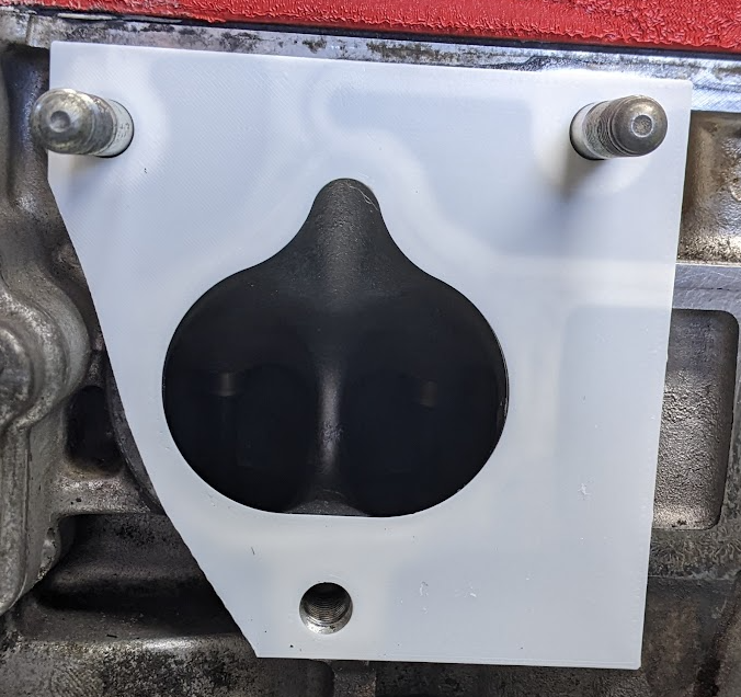
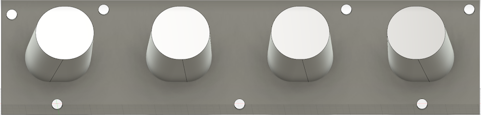
Nice work on that DTM panel! Looks good, been thinking about doing something similar.
However will you be doing anything to index them or add a keyway or something, so you cant plug the wrong plug into the wrong one?
Or colour coding them or something.
(I'm here to steal ideas)Yeah so all those thoughts crossed my mind when I did it. At the moment I have none of that.
Each connector is numbered on the loom and the bulkhead plate is numbered, but that's obviously not a fool proof solution.
Keying would be hard, you would have to machine the connectors down to put it in, and I'm not sure how much material is there to do that.
I had thought of printing color coded wrappers for them then glueing them on.
Can't use dummy pins as each connector doesn't have many to begin with.
I have made each connector very similar, e.g. 12v always on pin 1, 5v on 2, sensor ground 3, so it limits the risk a little bit, and coils/injectors are all interchangeable with no risk.
However my biggest concern is swapping the EWP with the ECU ground, if that happens then it's a straight path from fuse to ground.
So no solid solution at present, but open to ideas.
-
1
-
-
- Popular Post
ITB's Next Step
So the wiring is now done just needing testing.
The ITB's are a long term thing I need to slowly work through.
So while rewiring I pulled the manifold off so I could measure the ports and create a flange in CAD so I could slowly work on the manifold adapter.
So much crap on the internet
I did a lot of research on the internet around K20 ITB's and the port sizing, and can confidently say some manufacturers have both the port angle and port size wrong in their drawings (and that's their job to get right) Jenvey are definitely the ones who have it the dimensions right and that's backed up by feedback from someone who has tested a few and found them the best.
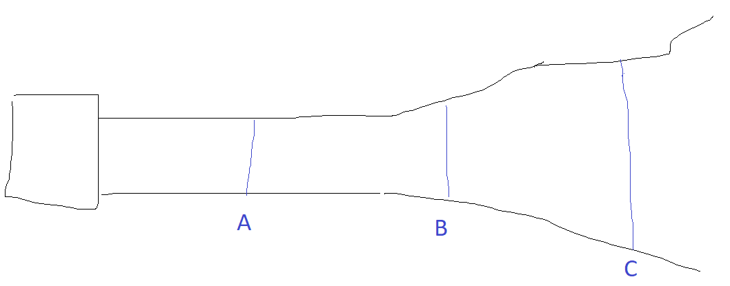
The jenvey ones are 48mm and everyone says that bigger then that is better (e.g. 52-54mm), but that ultimately depends entirely on where the throttle blade is positioned with the system.
e.g on the following diagram, A, B and C are all different plate sizes but really have no impact on the amount of air being ingested, however position does have an impact on response and driveability (closer to head being better).
So the Honda K20a CL7 port size is equivalent to 46mm throttle plate, which means if you put the throttle plate at B (48mm) you have accounted for the restriction it causes.
Jenvey looks to keep a straight section (no increase/decrease in size) of 46mm diameter for a length of 85mm from port to throttle body flange. I suspect that is because you don't want to take energy away from the air by trying to increase it's velocity just before it goes into the head, but could also be packaging etc. I'm just speculating here.
Additionally Jenvey have the port angle at 17.5 degrees, which when I measure is perfect for dead center (vertically) of the port as it narrows. Where as they others have 14/15 degrees which means the top side has a sharper angle then the bottom (which is flat).
So I can see why Jenvey perform, their experience shows in actually getting the basics right.
So they are the ones to copy as I can't afford their full kit

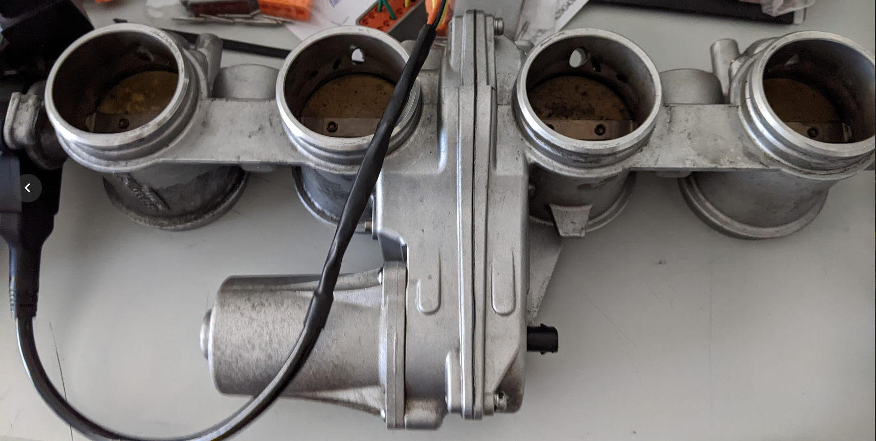
BMW S1000RR ITB's
Now the S1000RR ITB's are 53mm entry, 48mm plate and 42.84mm exit with a 3.5 degree taper on walls.
The exit is not good if port size is 46mm., however I'm confident I can bore them out with a little effort on the lathe to 46mm which would be perfect, I only need to bore 10mm into them, so don't have to worry about the throttle plate.
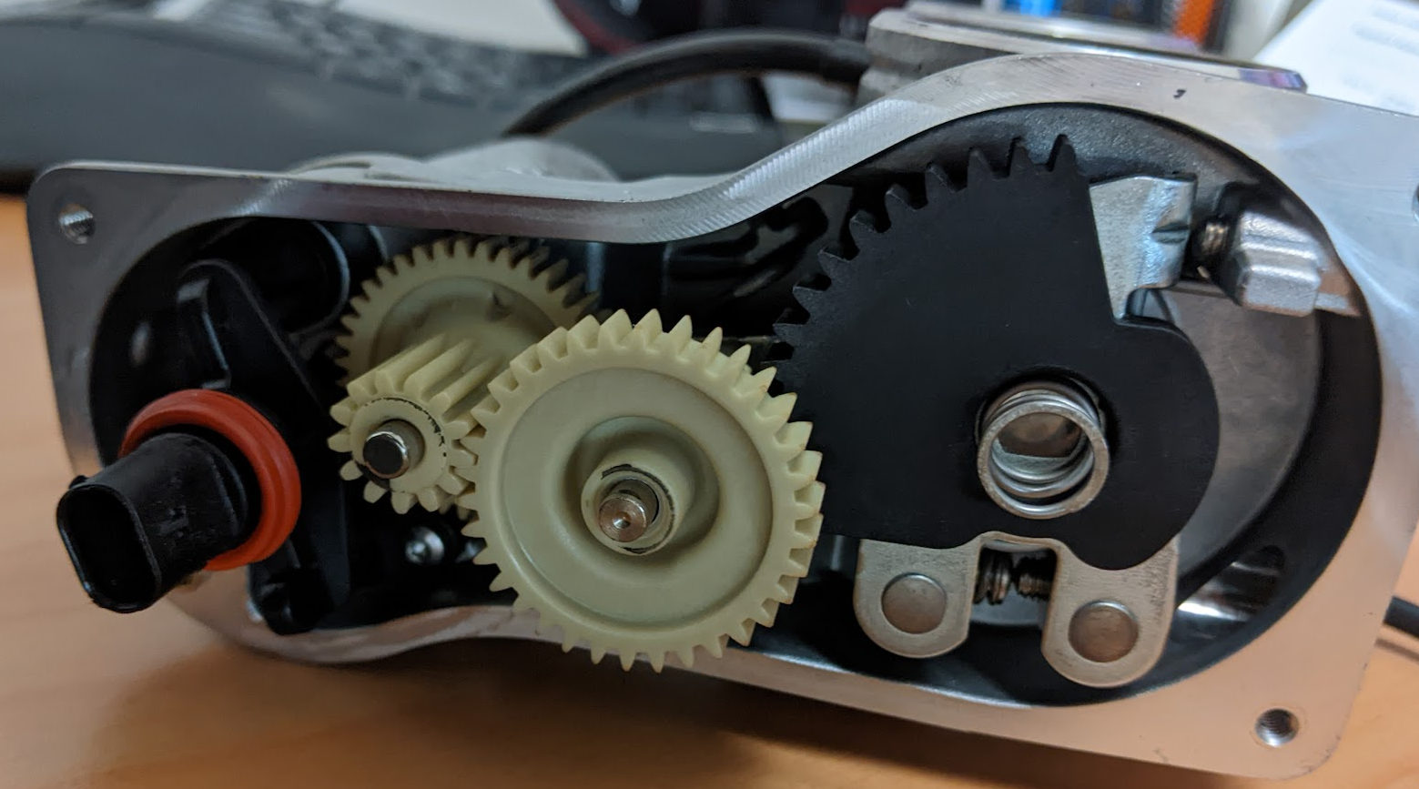
So I pulled them apart to see how hard it was and if it was possible to put each half on the lathe as is without having to completely dismantle the plates
Then they wouldn't go back together, a small bit of panicking later I was thinking I would have to dismantle them which would then mean they needed to be resynced.
But in the end I 3d printed a tool that now allows me to put them back together as they were from factory, so that's a massive win.
Bore spacing was the other worry the ITB's are roughly 83-82-83mm and the CL7 is 94mm, but it turns out that it's close enough that it will be fine.
So I can proceed with the ITB's and the design of the manifold to suit them.
My intention is to mount the standard Honda injectors into the manifold in the same place as the Skunk2 manifold (close to head) so that the transition of the tune to the ITB's is easier, then setup outboard injectors at a later stage (and just block up the BMW ports).
I'm not rushing this so it will be done when it's done.
Just in comparison here is what others have done to fit bike ITB's to a Honda K series.
https://www.jimbositb.com/product-page/throttle-body-adapter-plate-k24
Feel free to tell me I'm an idiot here;
-
16
-
 1
1
-
- Popular Post
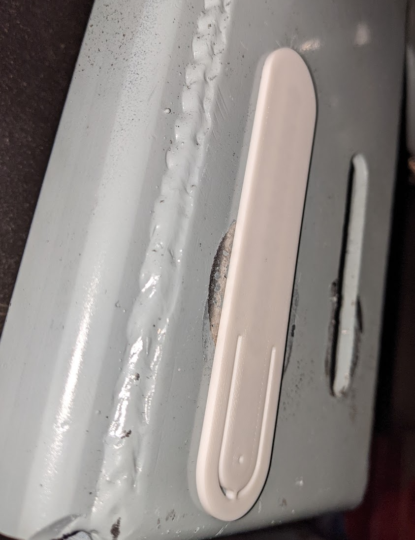
So I acquired a 3d Printer a wee while back and I've been learning how to design and create prints, and I finally had a cool job race car job for it.
I needed to lengthen the Watt's linkage slots so I can lower the linkage to get more grip out of the corners, and it's really important they are straight to keep the axle alignment.
So I 3d printed an insert that I could then outline the slot and center point for drilling the end of it out.
Worked a real treat and allowed me to do a much nicer job.
So the big downside of using @Roman ITB's are they are electronic, this means 2 TPS sensors, 2 pedal sensors new relay to supply power to the B plug of the ECU controlled by the ECU, and repinning and moving connections around.
I had thought at the time when wiring the car about DBW and thought "na I'll never go DBW"
Sigh.
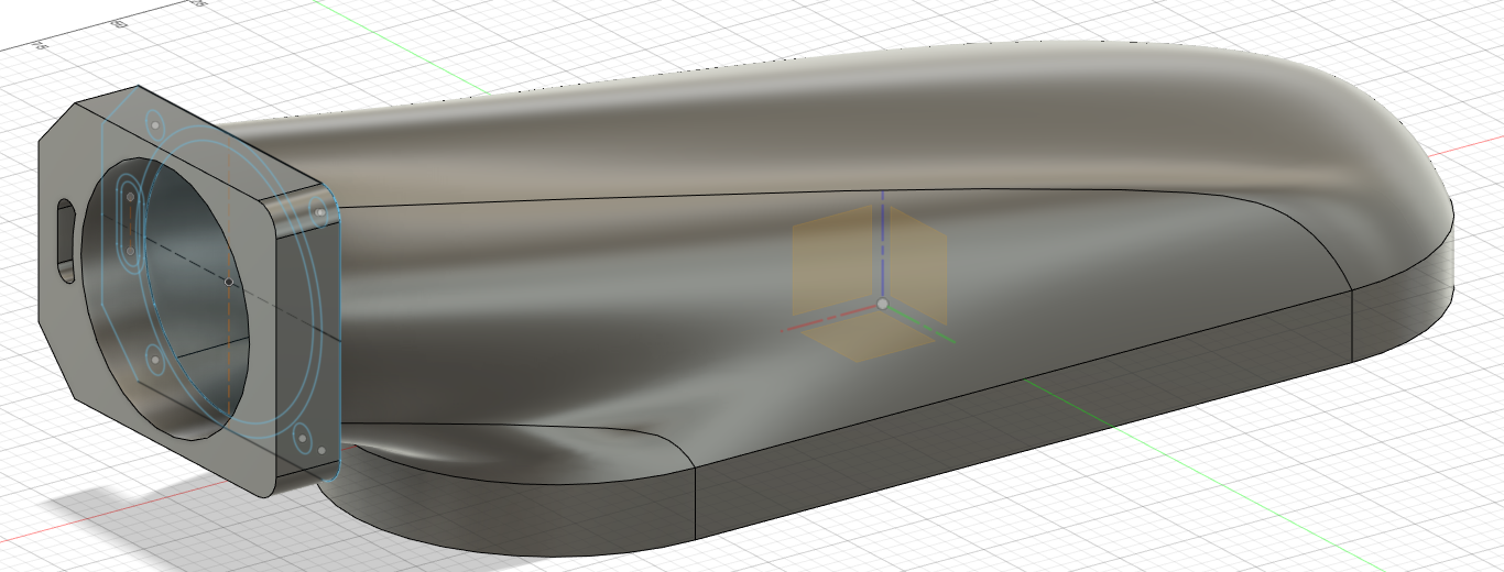
So knowing it was a pretty big job I thought it might be worth remarking the top of my current manifold as an interim measure, so with Daves help I designed up a new top cover.
But once I got to that point I could estimate the amount of material need to print it and I was also very concerned with the strength of it hanging off the side of the engine with throttle body with the only attachment being bolts threaded into it, I'm sure it's all solvable with time and effort, but I knew I wanted to do ITB's so scrapped that plan. It did give me lots of experience designing a complex shape which was good.
So onto the wiring job.
My goal was to rewire ready for the ITB's but still run the Intake manifold for now.
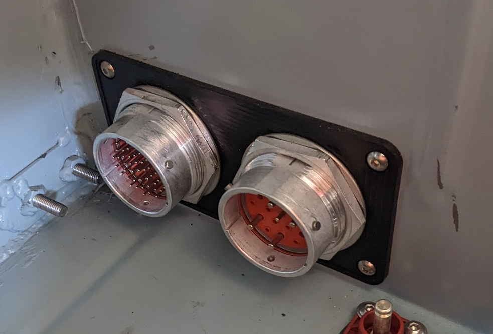
So I previously had these bulkhead connectors to the engine. And they are nice, however having had them on the car for a while I wasn't happy with them.
They are big, but more importantly they are impossible to work on e.g. good luck getting the very center wire out. They do make it much easier for when testing the wiring as they provide a nice test point for connections, but otherwise they are really ideal for if you had another engine with the loom ready to go and drop in, but in reality I'm not a big race team doing that I'm just a club racer.
So my goal was to create something that was more modular that I could upgrade/add bits over time easily.
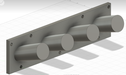
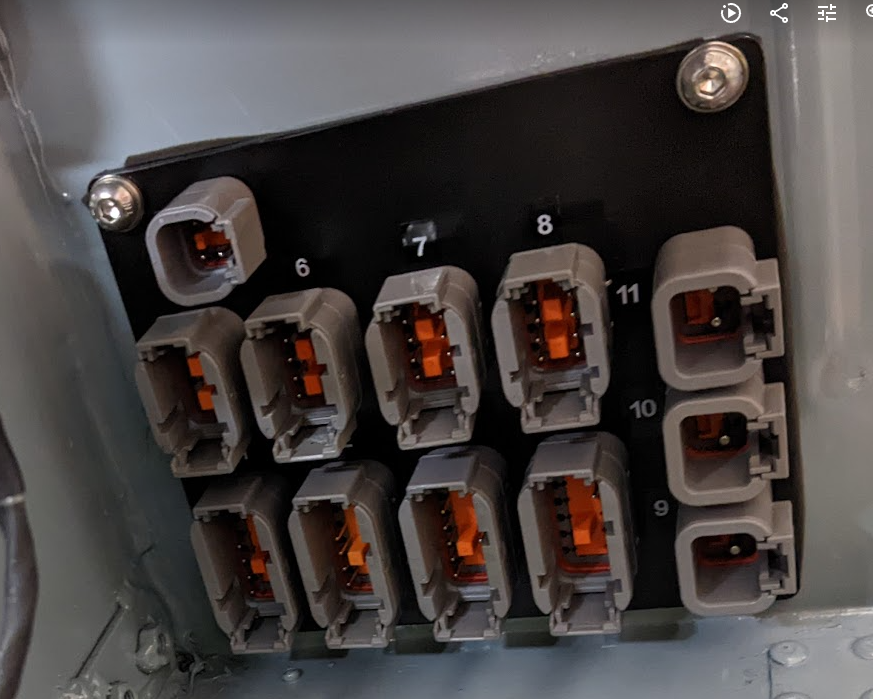
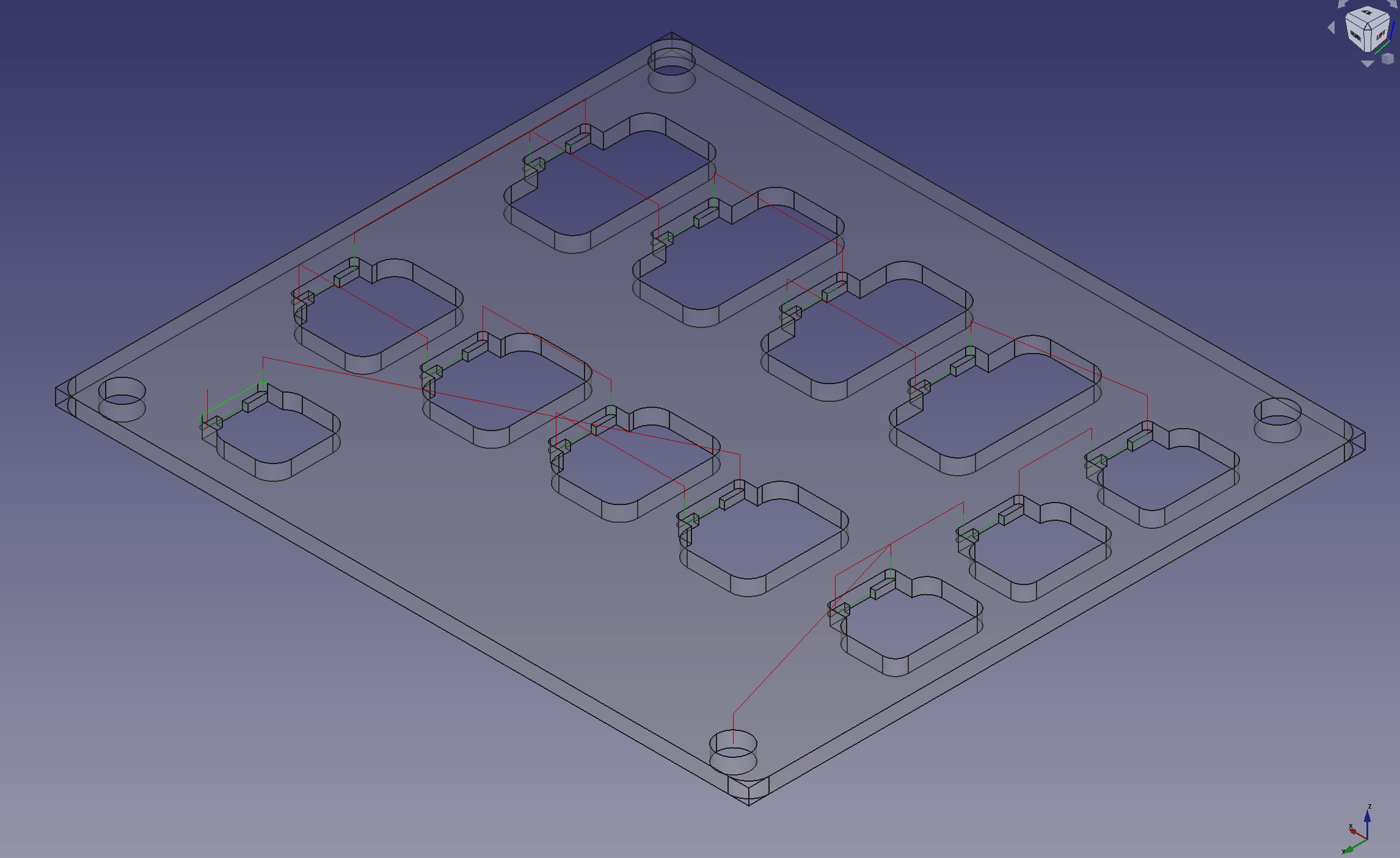
So I designed this in Fusion 360, printed mockups got it to how i wanted it, then had it laser cut and then @ajg193 machine the slots for the clips on the back side.
It has standard Deutsch DTM/DTP connectors which were a bitch to work out how to retain, and they still aren't quite right (but that's to do with the clips on the back and I think I can do something better).
But it will work for now.
Really happy with how it turned out.
It runs the following.
- 1: DTM12 (Front of engine) - Crank, Vtec, VTC, Oil Pressure, Oil Temp
- 2: DTM12 (Back of engine) - Exhaust Cam, Intake Cam, ECT, Starter, Alternator feed
- 3: DTM12 (Intake) - IAT, MAP, TPS Main, Fuel Pressure, ISCV.
- 4: DTM12 (Front of car) Transponder (can deal with lights etc in the future if required)
- 5 DTM8 (Gearbox) Speed sensor
- 6: DTM8 - Ignition Coils
- 7: DTM8 - Inboard Injectors
- 8: DTM8 - Outboard Injectors (not used at present)
- 9: DTP2 - ECU Ground to engine head
- 10: DTP2 - EWP
- 11: DTP2 - Fan
- 12: DTM4 - Can Lambda
Connector 3 has everything wired up for the ITB's as well so just need to change engine side to suit, also potentially supports variable velocity stacks (BMW S1000R comes with them as standard).
The idea is If I suddenly need a new sensor, I can easily splice it in to the engine side, and just run a single wire back to ECU.
I've also wired extra sensors into the steering columns for the pedal sensors and clutch in the future so they will be straight forward to add later.
Car is finally back together, It's running but I need to get it out on track again just to make sure everything is still good.
-
14
-
2
-
- Popular Post
- Popular Post
On 19/04/2023 at 19:42, ajg193 said:Just did a nice little machining job for @Hyperblade, adding a few features to a laser cut bulkhead plate for deutsch connectors
The little NC mill only had 1mm of extra Y axis travel to spare with cutting the features.
Hopefully it all fits together well when on the car.
Big thanks to @ajg193 for doing the machining for the connector clips on the plate, was very impressive seeing his setup and how quickly he managed to do it all.
Very happy with how it turned out.
-
10
-
Stick with J160, becoming more popular which is good for parts and some amount of crossover with other variations of it is good. It's a good box. And if worried about torque just do the fix the Silvia guys do something internal which I can't remember specifics of.
-
1
-
-
On 24/02/2023 at 17:57, kpr said:
If you wanted to try something in the meantime, you could take the spacers out of the plenum. Have some thick head flanges cut to space the manifold out at the head end, lengthening the intake runner. Maybe a couple at 25mm so can stack them see what works best. I'm guessing around 50mm would do the trick. Maybe could get them cut from something for some thermal insulation at the same time.
That's actually a really simple idea to increase the length.
But it would affect my bracing underneath and way more then i want to do to it at the moment.
My plan is to 3d print the top half and straighten up the throttle body + intake for the experience in doing that without having to take the whole manifold off and I want to see if it actually does make any difference.
Then I can get stuck into the ITB's which i know will be much better, but are going to take a lot of time playing around with redoing wiring.
-
1
-
-
16 hours ago, kpr said:
runner diameter being a bit oversized isn't actually much of an issue. unless its way oversized.
length is probably an issue though.you can see its doing something weird on the dyno sheet, which is most likely the intake runner length. looks like its wanting to work at 8500. which makes the dip at 7500. if the runners were a bit longer (most likely factory length) so it was tuned for 7800-8000rpm would make more power. its something that can be shuffled with the cam timing to a point also. your tuner probably should have already tried that though.
Ideally get those itb's on and make the intake runners way longer. nothing off the shelf will get you there either due to fitment issues, or too hard to make.
I'm pretty sure it's quite a bit larger then than stock, but hard to remember now as haven't had it off in a while.
Dave mentioned the same thing about the uptick at 8500rpm,
He estimated it's down 10 to 20hp at the top end, compared to what he's tuned before with stock manifolds.
ITB's require a bit of a rewire so due to being electronic and pedal changes so I'll plug away at it all and get it to a stage when I can then bolt them on at the right time and see how they go. But my quick measurements show I need to get them as close to the heads as possible.
Thanks for the feedback by the way, really appreciate it!
-
On 21/02/2023 at 21:56, kpr said:
Oh and the intake plenum size. probably aren't loosing any power there, unless your loosing some effect from the intake tube. bigger plenum damping out the pressure waves, unsure how much of a thing that is. There will be a little bit in getting the intake tube the right length and size. but wouldn't expect big numbers from it.
Agree on plenum size, everything I have read is that you can't really go too big.
But I do agree it's Intake system related.
Which is not unsurprising to me, I knew when I put that manifold on that it wasn't great, but it was the easiest one to do at the time and I knew I could fix it long term by going to ITB's (always the intention).
To be clear it's issues are
- Build quality was shocking, chunks out of the trumpets (which I had to fix)
- Everything was rough as guts
- The runners are HUGE
- Their own thermal gasket they provided actually blocked off the top of the port (yes seriously), so i used the standard honda one.
- It doesn't actually match the head ports perfectly (slightly larger if anything)
- The design of it is clearly more aimed at turbo cars.
The throttle body is 74mm,
- I don't think that's the issue.
- Although it's worth pointing out just to show how bad Skunk 2 is, that the gasket that comes with it doesn't fit correctly for the IACV port to their own manifold.
The intake filter and pipe
- The filter doesn't really have an internal velocity stack, and I did my best to improve it, but it wasn't a good job.
- The pipe has 2 bends opposite each other, then a 3rd bend after the throttle body for the air to get into the manifold velocity stacks.
- Most Hondas run a significantly longer intake pipe, mine is very short. Length helps the air to build up velocity before encountering obstructions like throttle body, corners etc.
The shitty pod filter velocity stack, bends and shortness of the pipe means the air is moving very slowly and never gets a chance to speed up so by the time it gets to the manifold and with that the runners being larger than they should be, the air never gets the velocity that the high RPM needs to fill the cylinders.
That's my current thinking anyway.
-
30 minutes ago, kpr said:
Yeah you can see the actual timing (yellow) misses the target (pink) by a little when you get back on the gas. but by the time your at full throttle its matching the target.
top one is your current "vvt" map. since race car and assuming you dont care about fuel economy, I'd run something more like the bottom. or a less aggressive ramp at least. so your always on target when get back on the gas. Not really much of an issue in your case but thought would explain it better.
Ive compared mine, which essentially mimics at 1j/2j setup vs @Roman daves 1nz setup and seems to react pretty similar. yours seems a little faster. either a honda thing or the control is a little better in g4xThat's brilliant, I understand what your getting at with the changes now. Even if it was 15 to 25 (assuming degrees) then it would take a big chunk of not being on target out of that curve.
-
58 minutes ago, kpr said:
I was going to comment about probably changing the cam timing map. so it doesn't go to zero cam advance when throttle is closed. due to the mechanical time it takes the cam to re advance when get back on the throttle.
but looked in the log and looks like it keeps real well. nice one mr honda. so isn't really that much of an issue. possibly a little more crisp on the throttle if changed it.As for what cam timing it needs. will need to be done per engine. unless 100% stock to 100% stock. as changes to the intake and exhaust will change what cam timing it likes.
The shape of the cam timing map looks right. starts to retard at high rpm etcThis as part of the log @Hyperblade posted. cam stuff at the bottom
The vvti control works real well even on my old g4 link.
Thanks for posting that screenshot, helps me understand what you are all talking about!
-
15 minutes ago, cbDrift said:
Had to sign up just so i could reply after i got your youtube reply and saw you uploaded your map.
Its a very similar tune to my jdm civic k20a timing wise - very close all the way through under load - a few deg more at the top end than me but im paranoid about not wanting any knock. generally within 2ish deg of mine under full load with mine running a bit less than you 99% of the time
But your cam angle map is totally different to mine - and on these k20a engines - it makes all the world of difference getting that right in all conditions with an n/a engine.
i gained a "buttload" (technical term) of top end when i got the target cam angle to actually match up with actual angle using this target cam angle map on my haltech
this is from my jdm type r k20a in a 2005 civic ep3 - the engine is untouched apart from intake and injectors and a decat
the difference between accurate cam tracking and having it waffle around vaguely in the range of the target is amazing - I got a tonne of drivability and my top end power when i had good control of the cam angle. 2deg can make a difference to how the car feels when driving - and cold oil heavily affects the cam angle tuning vs up to temp oil.
having said that - it looks like the link handled pid stuff totally differently to the haltech so i have no idea how accurate the link will track the target cam angle.
Either way - if this helps to improve your drivability - mint! if it doesnt - just as mint
")
Have fun - your starlet is an awesome build and thank you for posting your map to take a look at
I'd be really interested to see how accurate the link is able to track the target cam angle with the actual cam angle (even a screenshot of the two traces overlaid)
Welcome to the forum!
Unfortunately your talking way over my head, i'm just not up to speed technically on all of that stuff as much as I want to be, I just haven't had the time to really sit down and understand it all and be able to tweak it.
I should mention Dave said he usually has the timing backed off a couple of degrees.
The other thing to mention is that on the Dyno Jon struggled to get temp into it including the oil (5w40) which sat at about 80 degrees if i remember correctly (on track oil is hitting 120+)
Due to:
- The sensor reading 9-11 degrees lower than what the engine temp actually was
- The electric water pump control just not working well at all (hence I put in new thermostat + bypass hose)
I can do you one better though, here's the full log from session 4, i basically have everything logged as it has heaps of memory.
https://drive.google.com/file/d/1x3suRFYwUip95PEAx97Et83RMrr0hbNC/view?usp=sharing
I haven't updated the main thread, but current plan is to redo intake piping to be straight which means new 3d printed top half of the manifold so I can straighten throttle body, this should at least eliminate that from being a possible issue as I think the triple bend for the air to get into the runner is actually the main issue vs the plenum volume. I want to do that first as it's just keeps niggling at me(and I would like to know if I'm on the money or not around that stuff) and and it gives me more time to plan the quad throttles to get best results.
-
2
-
Take a breath, step back, study it, think about it objectively what other issues are going to crop up if it's not positioned where you were originally planning e.g. steering, cooling etc.
Think back to your original goals with the swap, will it still meet those?
Now's the easy time to pull out if you think it won't work. If to fit it you need to cut up the car, that's a pretty major step and easily spirals into a lot of other things.
Whichever way you go I'm all in and following!
-
1
-
2
-
-
- Popular Post
So things have moved along rapidly in diagnosing the power loss. Lol
I had Dave at Dtech motorsport look over the tune and logs, as he has tuned more then a few honda K engines.
He was fully happy with the tune and thinks it looks all good.
Best guess at this stage is the intake manifold (Skunk 2 Ultra Street with 2x .5L plenum spacers) is to big for the stock engine.
He advised removing the spacers initially, but unfortunately they are also used to get the throttle body into a position where I can get the intake pipe around the oil cooler duct.
So onto moving forward with my ultimate long term (now short term) plan which is ITB's.
Aside from the power gains (hopefully) they will mean I can do a really nice cold air intake setup. The car was built with lots of space in that area to play around as I knew I would eventually end up at this point.
The recommendation from him is Jenvey Tapered ITB's as they perform the best.
https://store.jenvey.co.uk/honda-k20-ep3-sf51-taper-kit-ckha07-kit
I don't have the money for that, so over the coming months (in no rush for this) I'm going to backyard build a setup.
I have aquired Roman's BMW S1000RR 48mm ITB's and will 3D print manifold, trumpets, airbox, intake to suit.
It's electronic and I currently run throttle cable, but I think I have enough outputs/inputs on ECU and can just buy an new linkage kit for my existing pedal (https://tiltonracing.com/product/600-series-throttle-pedal/), that it probably makes sense to keep it electronic and not need to put Idle up valve in.
Just going to be a lot more wiring i was trying to avoid. however the benefits probably outweigh the pain.
-
17
-
1
-
This is going to be so fucking awesome, and for what your doing which is not an all out racecar, makes a lot of sense.
And even if it doesn't work out, I'm along for the ride!
You are mid mounting it right?

-
2
-
-
7 hours ago, Roman said:
It's been bloody awesome fun alright.
But also it's a bit tapped out now.
You cant get any 1NZ cams bigger than 264 deg, and there were only "admin" sorta jobs left to do like sort out an air filter or tidy it up.
Things which made the car nicer but fundamentally didnt alter the recipe any further.
I'm actually really happy to end a project on a high note.
It seems a lot of projects end up being sad to look back on if they ended when a car was crashed, or motor blew up, or sold to have kids or whatever.
This has just been grin factor 10 nearly all the way through.
Also I've managed to infect some other people with the concept of vitz pesting, and the parts from this car are going to be used in some cool setups.
Also worth noting that back when this car was standard I came incredibly close to just giving it away as I no longer used it.
What an absolute adventure it's been on, at the tail end of it's life instead.
How good!
I think what you have done is bloody amazing!
It's been so cool to watch as you have progressed with the development and tried things.
I agree it's reached it's natural conclusion without a lot more major work.
I don't believe you can ever work on 2 project cars at the same time and give them both serious attention, so it's going to be awesome to see you get back into the carina.
-
3
-
1
-
-
10 hours ago, Roman said:
Ahh man there's always something eh!
Drive from last shakedown looked good, stoked to see it's making steady improvements.
Would love to check out your car one day, love it.Anytime your down here in Chch (or anyone else who wants to see it) just give a yell.
-
1
-
1
-
-
- Popular Post
So I went for a shakedown with new clutch, which overall went pretty well.
I got a comment on one of my videos which I thought I would answer here as it's long and complicated and may interest others.
Quote@cbdrift5864
Its the first time ive seen it driven in anger - this thing has some serious front end bite and sounds like its VERY enthusiastic Good job! From the looks of your dashboard your running a link ecu? Have you had this dyno tuned or just doing it yourself from the basemap? I have a jdm k20a on a haltech and im always curious to find/swap/get more info on tuning the engine on an aftermarket ecu - especially the cam control side of things which i spend a lot of time on.
Map
First up, I don't mind sharing my MAP so others can learn, It's for a LinkEcu G4X XtremeX and you can download it here
https://drive.google.com/file/d/1-M1MXHnkJxH2A30xRdFbANd65I309fiA/view?usp=sharing
Tuning was done on a dyno by a specialist, so can't add any extra info there, other than maps were done for non vtec/vtec then it was worked out where the crossover made the most sense (4500 rpm).
Driven in Anger
The comment about it being driven in anger is a good observation. With the BEAMS in the car, I always felt the car was hard to turn in, and if I tried to be aggressive it would just understeer. That plus suspension valving issues, rear brake pads accidently being to aggressive, I never felt comfortable pushing it into a corner and so was reasonable gentle on the inputs to give lots of margin for error.
I have finally reached a point where we have made major suspension changes, lengthed wheel base, anti dive, shocks valved correctly, rear pads correct, and 30kg taken directly off the front end, where I'm finally feeling comfortable in the car.
However I'm still used to driving the car fairly gentle, which you would see in 2nd shakedown video from the same day on my channel.
I got Brent who did the fabrication and who has driven a wide range of very fast race/rally cars into it for the 3rd shakedown video to see what he thought, he came away absolutely loving it the handling with no changes required to valving, or sways bars or anything major which we are both stoked about.
But he did have the following comments:
-
Could do with Power steering (will explain why below)
- Suggested Suzuki Ignis mid 2000's electric steering column as you can get the aftermarket modules to control them and they are small.
-
Power is not what it should be in the top end (suspects down 20hp)
- suggests shortening secondaries.
- Suspects that they are to long and it's affecting scavenging at high rpm.
- Whole logs/fueling needs to be looked at to see what's happening first before going down that route (but i need to learn how to read them and adjust them first)
- Can easily see it on the dyno sheet, I've just lived with it for now as other priorities, but obviously something not quite right.
-
The watts linkage should be lowered to improve the angles
- this will increase grip on the rear end on exit of corners
- Shakedown video 5 has it lowered by 15mm, which may have felt slightly better.
- But have reach limit of adjustability, so need to lengthen the slots.
So the power steering is the interesting bit, the reasoning is that when turning for a corner the power steering moves quicker for less input, with the tyres I run if you turn in very quickly initially (you can back off afterwards) they hook and get a lot more grip then you would normally get.
I have never had the car in the state before where I felt like throwing it in would work or that I could safely control it.
So Session 4/5 I changed my driving style to try initially turning the wheel into a corner really fast.
Holy hell, it was an amazing feeling that i have never experienced before, it blew my mind, it was hard to compute how much front end grip it suddenly had and the rear just felt like it slipped slightly then hooked up too, it's hard to convey how big a difference it felt but felt like I had at least double the grip on the front end.
As you can see in the videos (4/5), I was missing apexes all over the place as trying to time it was really hard. And that's why power steering is recommended as it means you just turn into the corner and the natural movement will cause it to hook at the right time. Where as doing it manually is slightly slower and timing it is harder.
-
13
-
2
-
Clutch:
So the aftermath of a clutch spring letting go.
Bit's also made a small hole through the bellhousing.
That was a new Exedy HD S2000 clutch, there were warnings on the internet about using them, I thought it would be ok as light weight car, and previous Exedy with the BEAMS handled a ton of abuse.
Wow was I wrong, DO NOT use this clutch, after taking it out we could see wear on the posts and clutch springs where they were binding, it's just not designed correctly for the loads.
Decided to try an Action Clutch (Considered Xtreme Clutch, but had a friend who's plate exploded on his car and made a bigger mess...) this time, at least the springs shouldn't be able to come out...
Adapter Plate/Flywheel
So while we were swapping that we found the input shaft bush was showing a lot of wear and was no longer concentric.
I run a standard adapter plate (with flywheel to suit), they say on their product page "Precision machined from 6061 this adapter features perfect dowel pinned alignment and all hardware needed."
Of course when I went to bolt it on one of the dowel pins wouldn't go in, I was in a rush for various reason and it become a one is in, that should be enough...
Turns out yeah no, you really do need 2, we think movement between gearbox and engine has caused it to wear, which damaged flywheel where the bushing sat.
The adapter plates also don't have a huge number of bolts holding everything together, especially at the bottom where their is the highest load.
Adapter Plate
Originally the gearbox bolted up to the adapter flange with 3 bolts (yeah I wasn't to impressed by that at the time, but a lot have been sold, so figured it would be ok), it's now been all modified to have 7, and more coming in from the engine side. We also managed to get one bolt at the bottom to go all the way through from the gearbox to the engine sump bracing (highest load). It won't be moving anywhere now...
We machined the flywheel to fix it up and put a proper bearing in it (2032 6 series - I think from b series), so that should also take some mis alignment better.
Engine mounting points, top of adapter plate sits above the top ones.
Gearbox Shifter Linkage
For any one interested, here's a good photo of shortening a gear lever linkage on an Honda S2000 AP1 gearbox to move it forward which i took while it was out.
-
9
-


-500x500.jpg)


STOLEN: Racecar Last Seen Heading North of Christchurch
in General Car Chat
Posted
Car and trailer have been found.