


Flash
-
Posts
1615 -
Joined
-
Last visited
-
Days Won
2
Posts posted by Flash
-
-
- Popular Post
- Popular Post
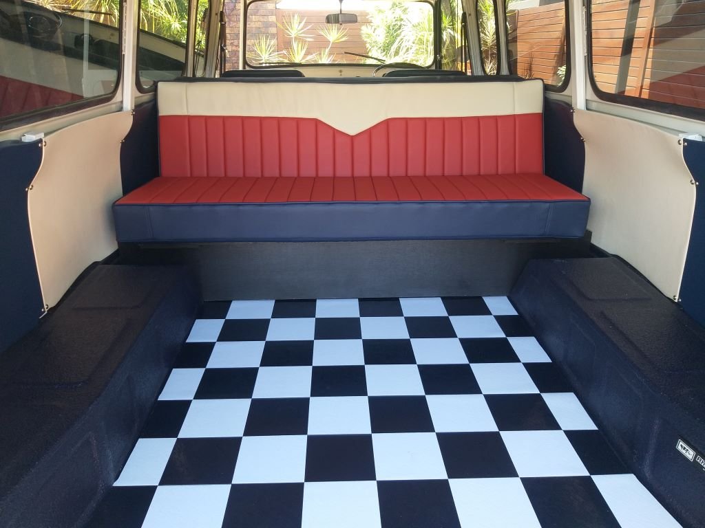
This year is one of those significant wedding anniversaries for Mrs Flash and I, so a few weeks back I asked my lady what she would like. Now most ladies would ask for some new jewellery or maybe a new outfit or two, or perhaps a romantic weekend away at some fancy resort. But that's just not how my girl rolls. Without even thinking about it she immediately asked if we could rather spend the money getting the upholstery work done for the back of the Thames. Jeez, no wonder I love this woman so much.
So, with the decision made off I headed to town to visit two of our local upholstery places. The first stop was at the auto trimmers. Now I get that these guys do nothing but cars all day, but I was still expecting the chap to at least comment on the Thames, but not a peep. He noseyed around with a measuring tape and then proceeded to give me one of those loosey goosey "between this and this" verbal quotes where you immediately know that the final figure is going to be nowhere near the bottom figure quoted and you are likely to get very little change back from the upper figure quoted.
Anyhoo, undaunted by his lack of enthusiasm I headed off to the next stop which is a place that mainly specialises in recovering furniture. Now as I pulled into their driveway, I spotted this guy scurrying across to greet me and we proceeded to yarn about the Thames for a good 10 minutes before we even started talking business. It turns out that Bill is originally from Masterton where his dad ran a motor trimming business back in the day. The minute that Bill was big enough to reach the pedals on the sewing machine he was put to work and by the age of eight he was already doing diamond stitching which was all the rage back then.
We chatted a bit about what I was looking for style wise and Bill was already throwing in some really good suggestions, so I knew I was on to the right guy. We looked at some samples, Bill took some measurements and the next minute Caroline the owner handed me a written quote that was significantly less than the first quote I got. Winner!
Roll forward a few weeks whilst Caroline sourced the marine grade vinyl material and some top-quality foam, and I then took the van around for final measurements. Because the cushions are loose, I didn't have to leave the van with them which was another plus.
Roll forward another week and late yesterday I got a call from Caroline to say that the cushions were ready for final fitting, so we wheeled through first thing this morning and Bill laid down some velcro to keep everything in place and then proceeded to do the final fit up.
To say that we are blown away with the results would be an understatement. The job has turned out absolutely amazing.
Rear facing couch looks like so:

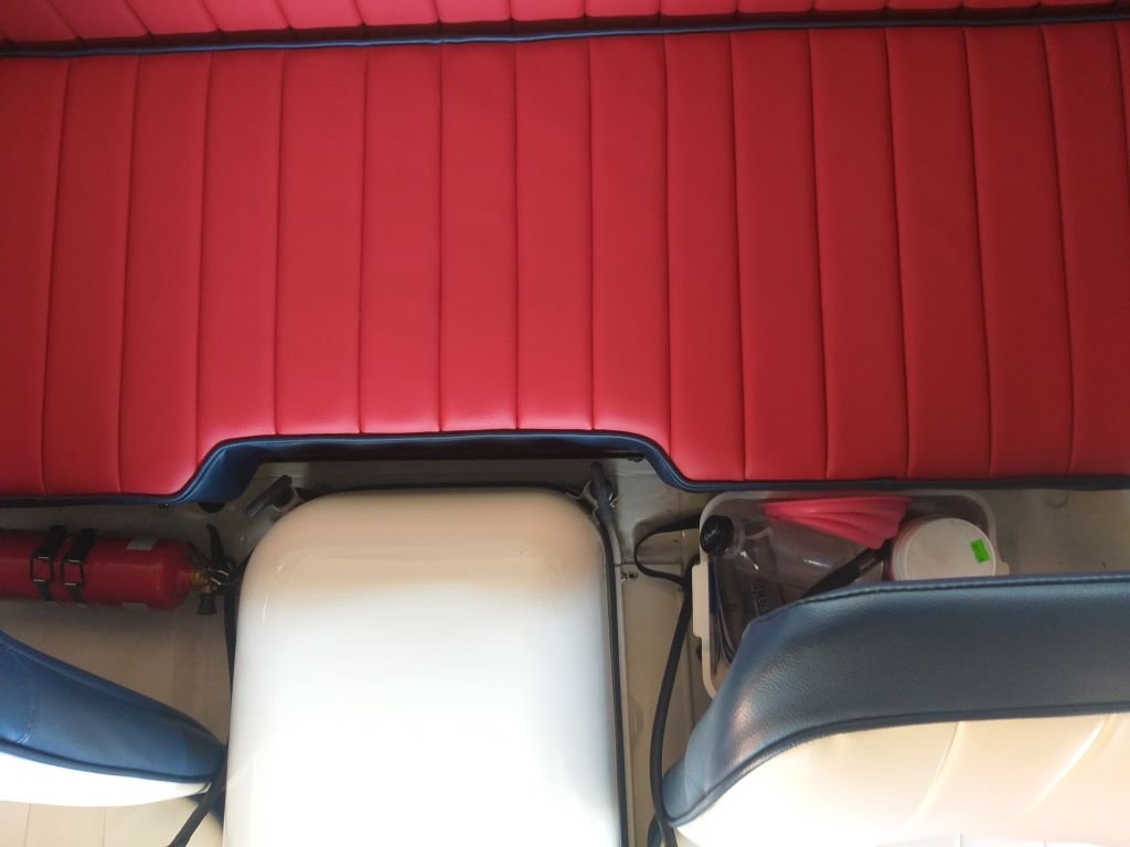
Bill even shaped the base of the front facing "dog box" so that it clears the engine cover tie downs:
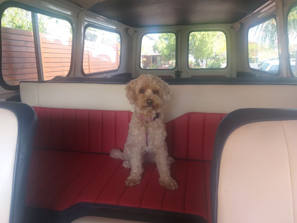
And lastly even our doggo seems happy with her comfy wee seat.
Thanks for looking.
-
 28
28
-
 2
2
-
19 hours ago, dmulally said:
I remember having massive dramas with this on my Commer van tank. For LVV I had to have a 1 way check valve on the breather and it made filling up awful. Used to just puke back at me at anything more than a trickle. I used to fill up jerry cans and use a hose line into the tank from that when I got home.
I ended up taking off the check valve which helped some. Then I made the breather bigger and plumbed it into the filler neck right near the top.
Probably didn't help where the inlet came into the tank at the half way mark:
Thanks heaps for the reply. Yep, I'm thinking along the same lines as you have gone by sticking an outlet into the filler neck. I'm so over washing fuel marks off the side of the van every time I have more than half a tank of fuel on board.
-
1
-
-
- Popular Post
- Popular Post
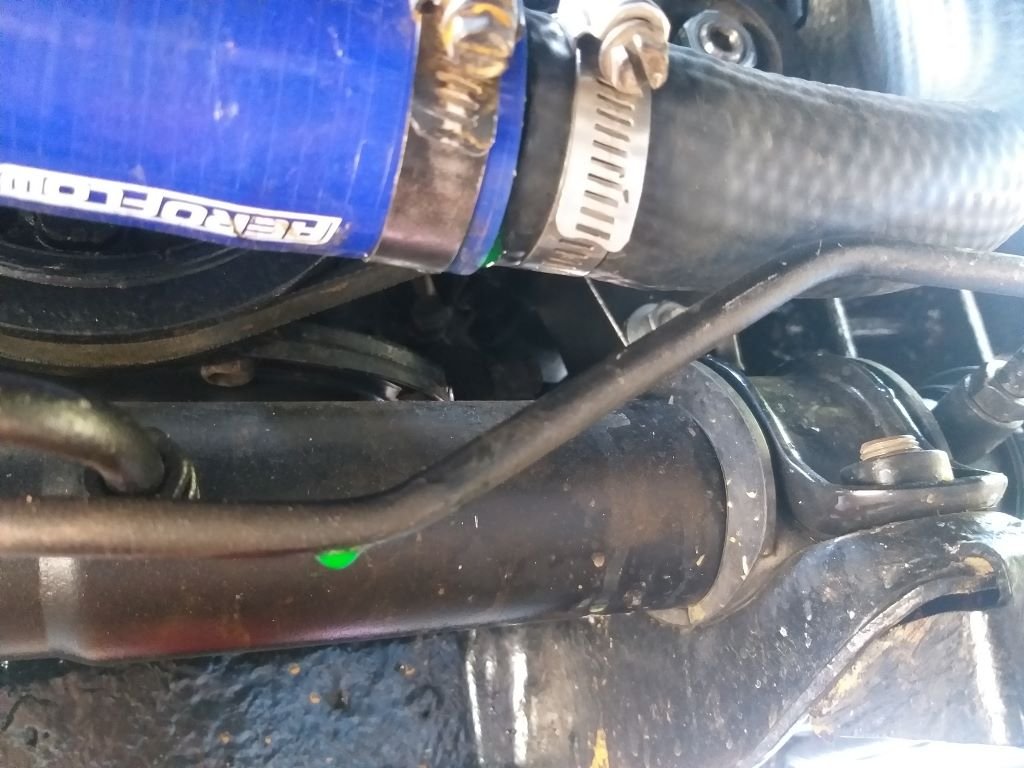
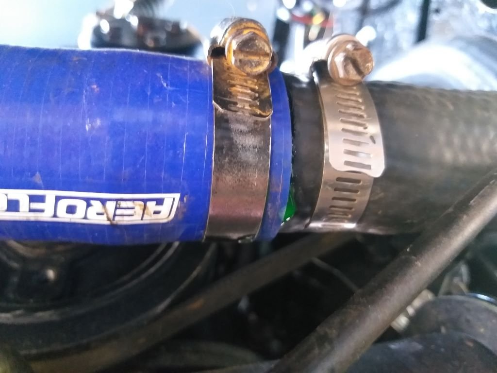
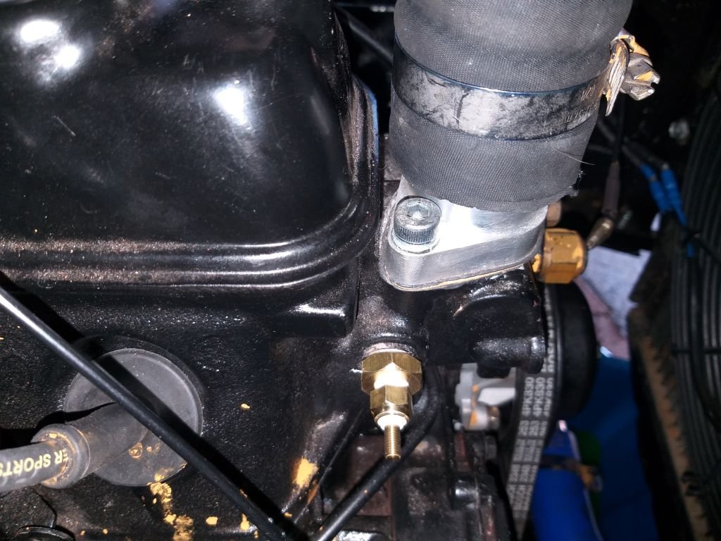
When I climbed under the Thames to remove the radiator, I noticed a slight weep right where my two portions of lower hose meet.
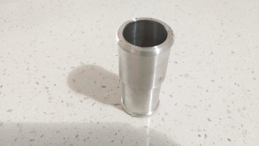
I was surprised as the engineering shop that had turned me up the aluminium joiner piece had done a really good job.
Once I had it all apart and on closer inspection, I suspect that the issue is the placement of the clamps. I'm thinking I've got them too close to the transition point on the adapter, so I've now spaced them further apart.
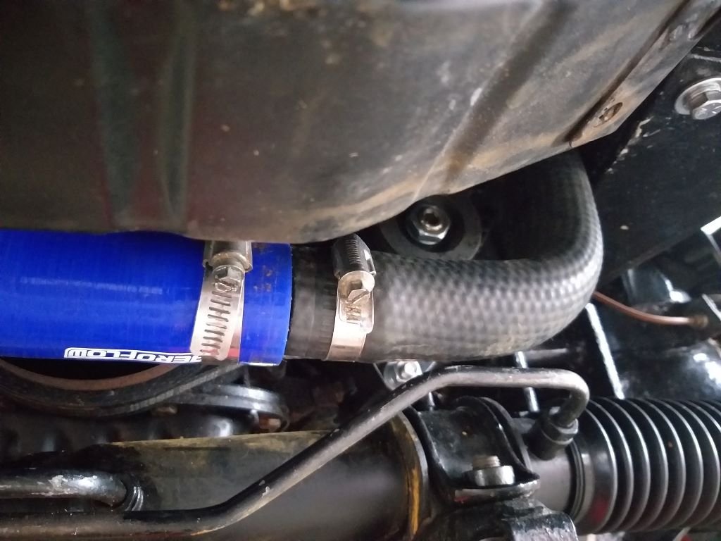
Took the van for a squirt around town to get the temp up then crawled under for a look see.
So far it looks good, but I'll keep an eye on things just to make sure.
-
13
-
- Popular Post
- Popular Post
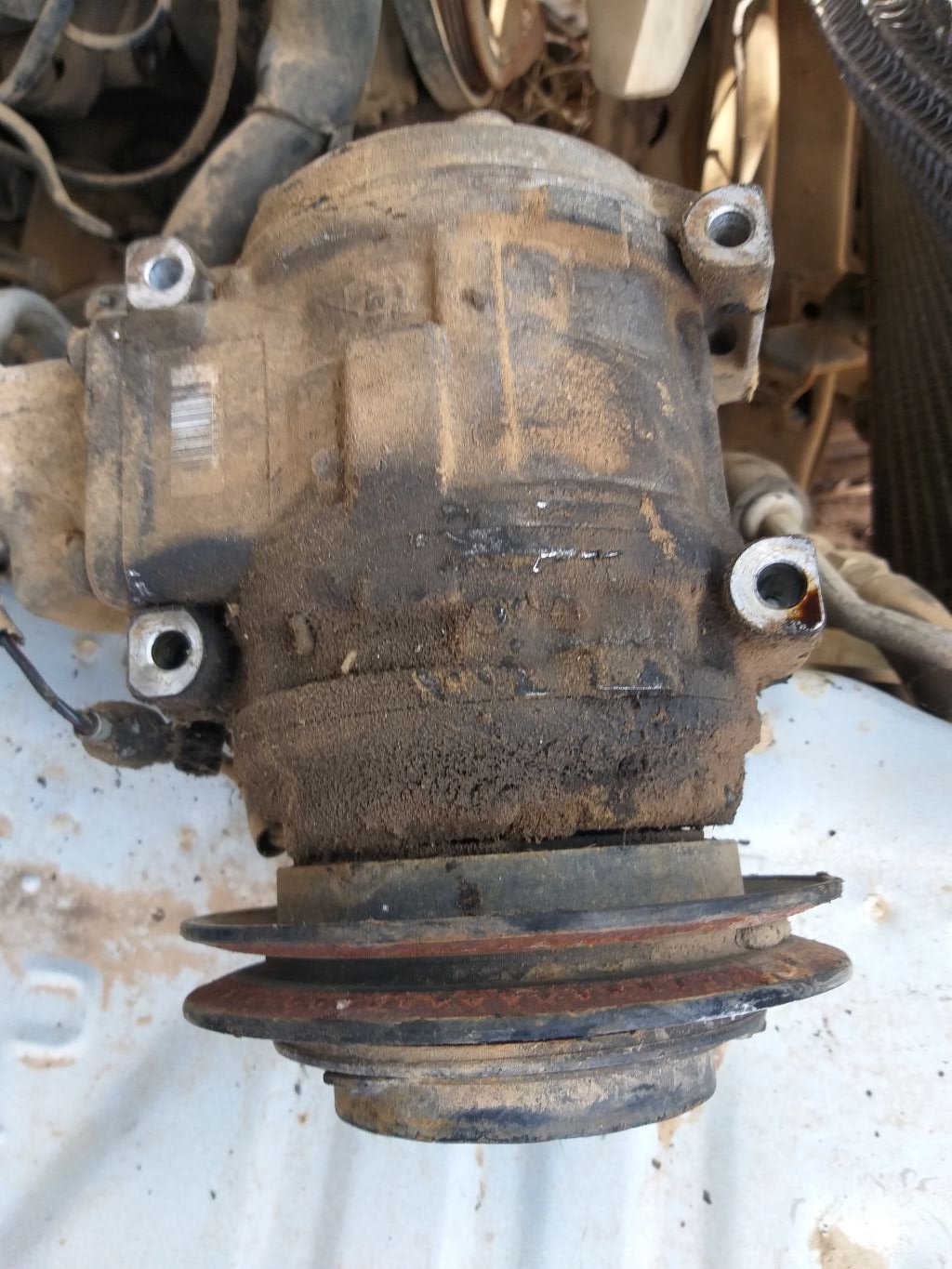
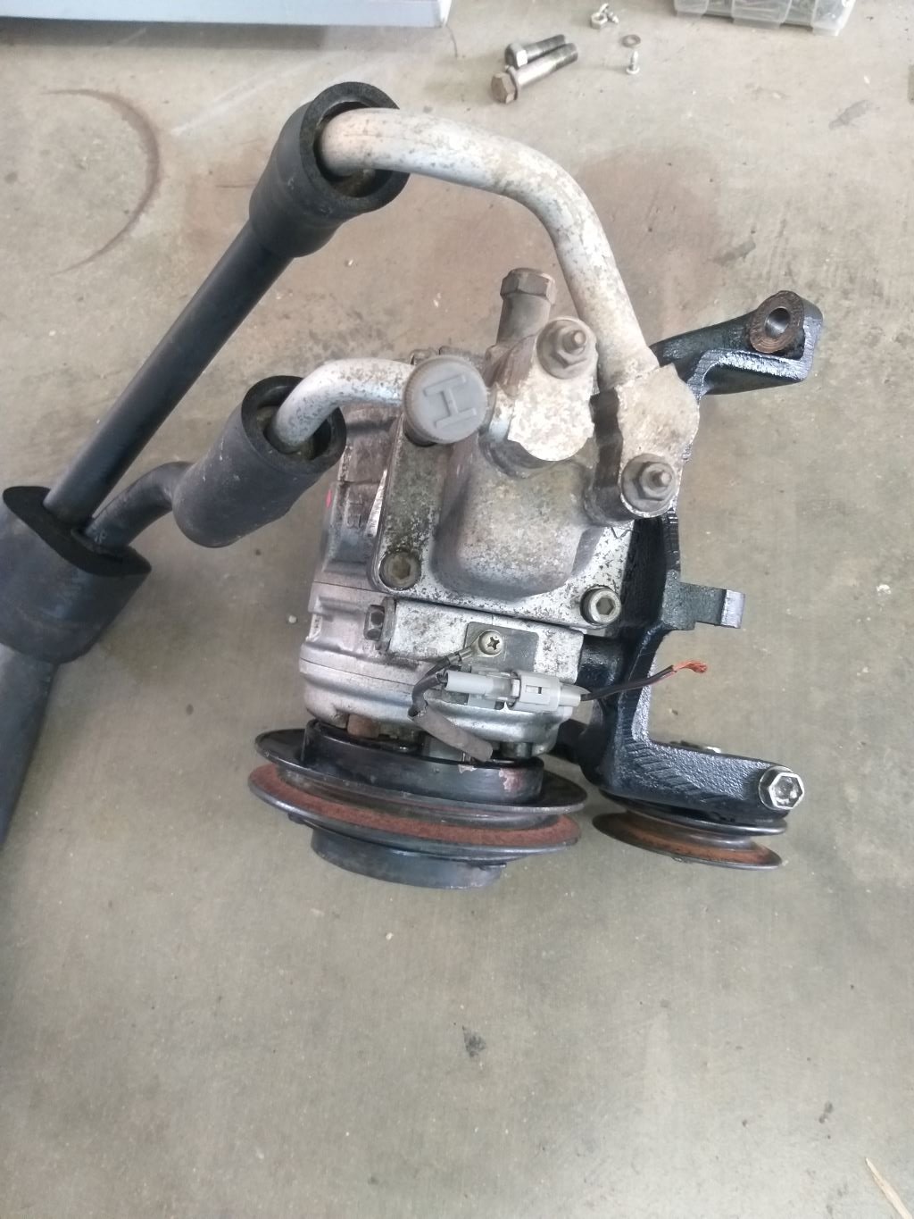
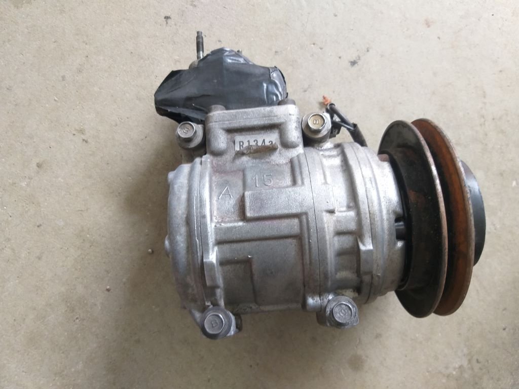
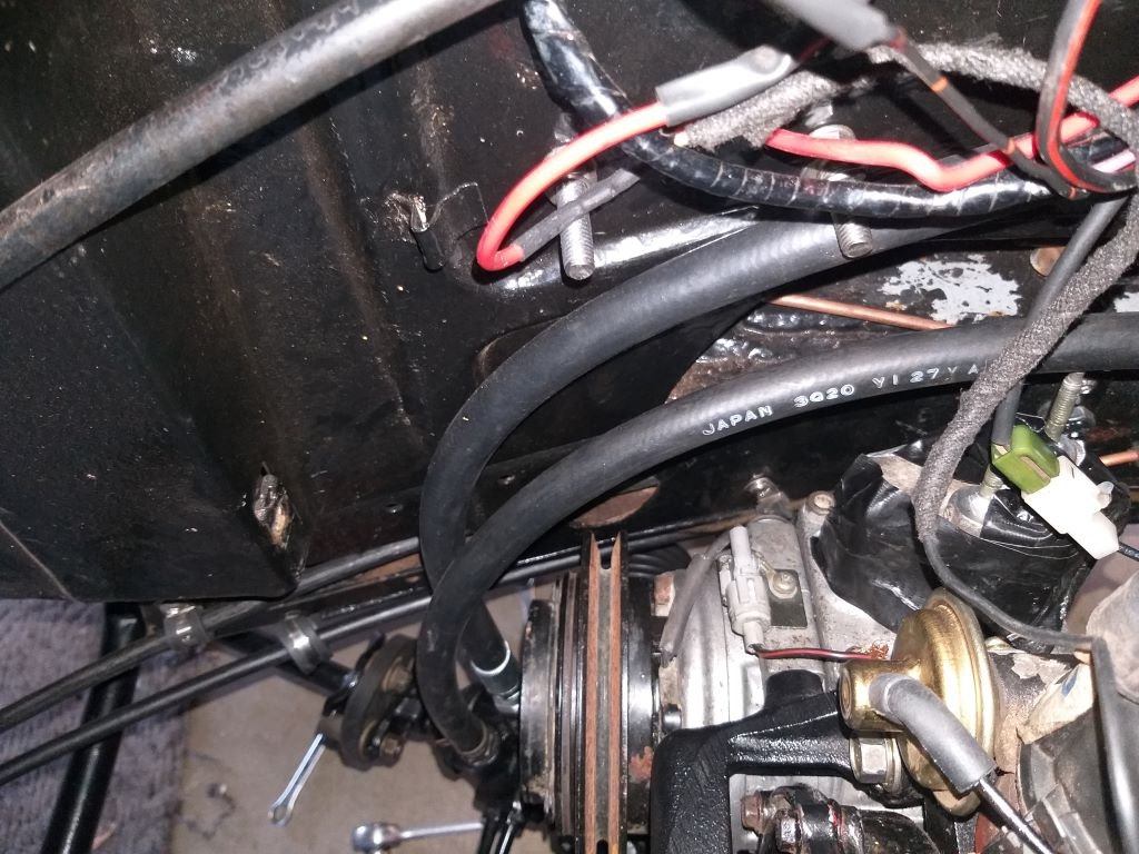
Those following along on my journey will recall that I managed to track down an a/c compressor bracket for my 3Y engine back in September. At the time I mentioned that I'd need to grab the compressor from the same wreck as I needed the pipe manifold. Anyway, after that update I wheeled past the wreckers on my next trip into town and grabbed the compressor. The good news is that it may not be as shagged as I'd originally thought as the system was still pressurised when I pulled the compressor off.
And this grubby puppy has been patiently sitting in the corner of my shed for the past six weeks:
So this weekend I thought I'd pull my finger out and get the damn thing fitted.
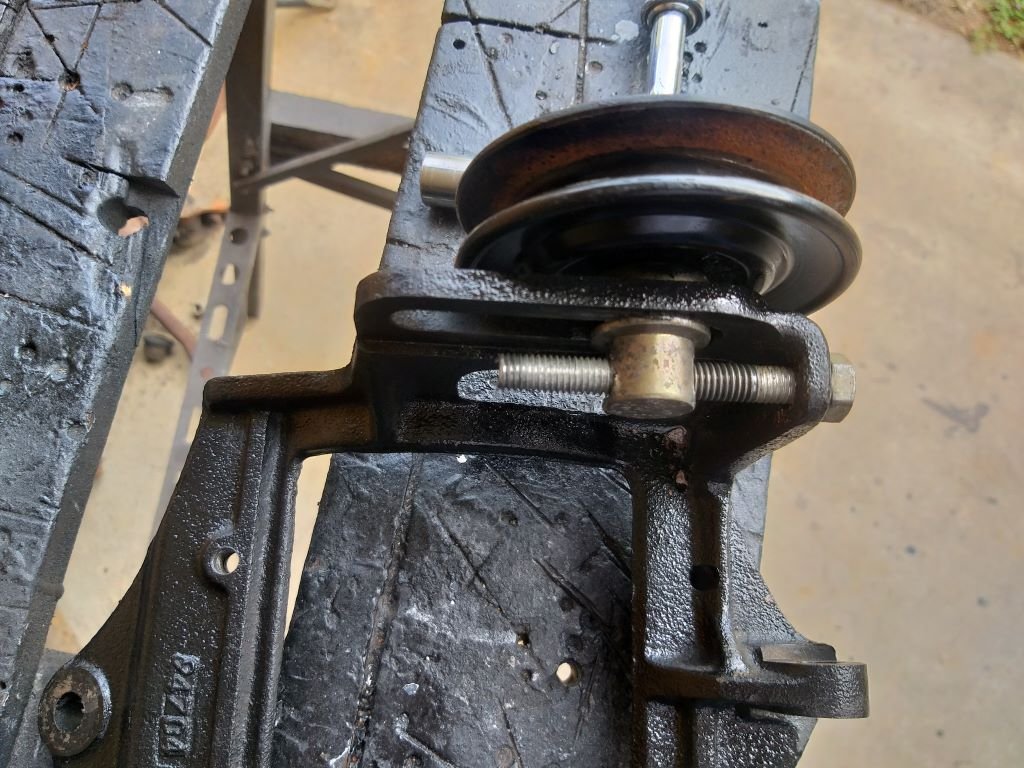
First step was to mock up the bracket and compressor on my spare engine. All fitted good, but when trying to fit the drive belt I noticed that the adjusting mechanism on the idler pulley had seized up. Used some heat, a few dabs of WD40, a piece of crusty old flat bar and a through bolt and managed to eventually free the thing up by using the threads on the bolt to force it one way and then the other.
This way to wind the pulley all the way down:
Then this way to wind it all the way up:
Repeat half a dozen times with liberal squirts of lube and she was good to go.
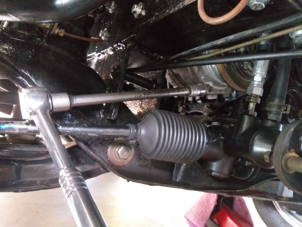
Next step was to work out how I was going to squeeze everything in between the side of the mighty 3Y and the right hand chassis rail.
After a quick look about I realised that this was going to be a radiator out job, so out she came.
For my first attempt I bolted the compressor to the bracket and then tried to slide the combined unit in from the front while trying to squeeze past the power steering pipework.
Instant fail. The a/c hose tails were in the way. So those came off and I tried again.
And .... another fail. The combined width of the bracket and compressor just wouldn't squeeze through the small gap available.
Scratched my head a bit and then decided to try sliding the compressor in first from underneath and then slipping the bracket down between the compressor and the engine block from above.
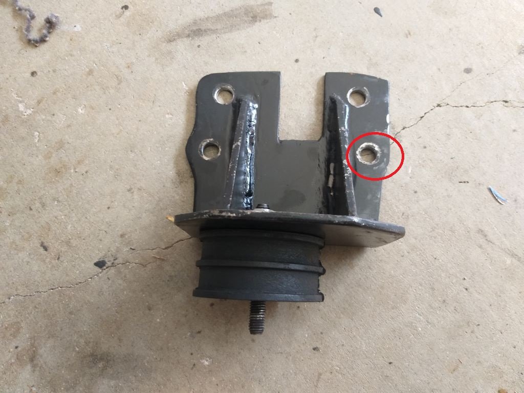
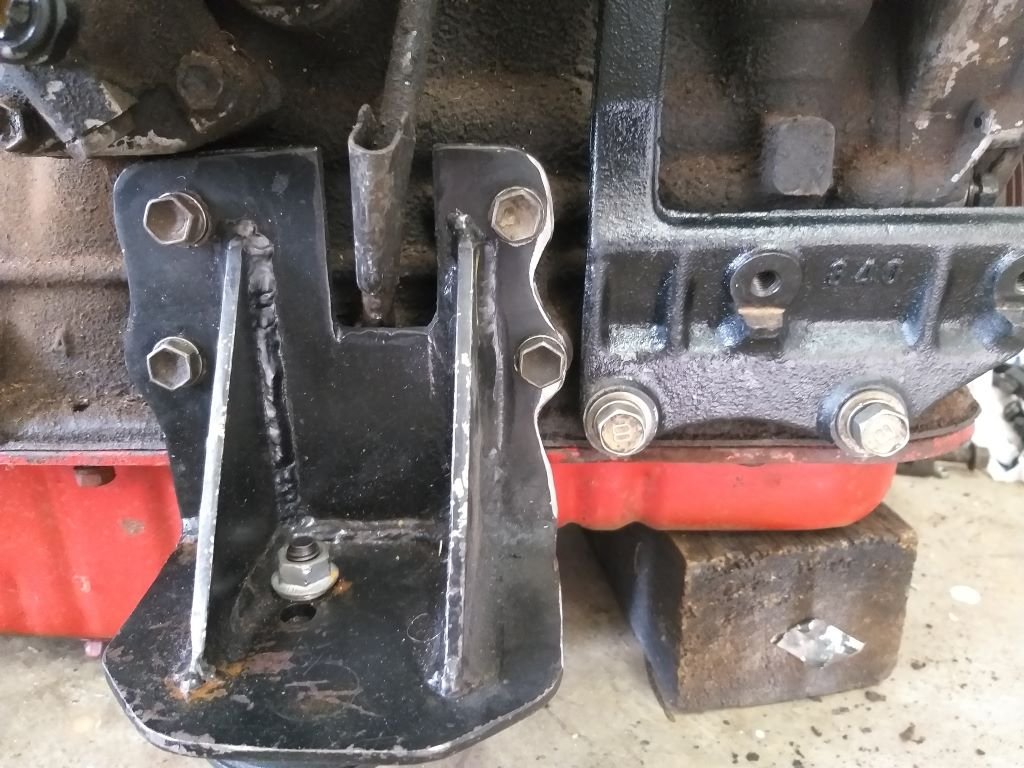
Worked okay, but when I came to bolt up the bracket to the engine I could only get three of the four mounting bolts to line up. Couldn't see past the compressor to figure out what was wrong, so I ended up pulling the bracket and compressor out for a look see. Tried mounting the bracket on its own and I immediately spotted the issue. The back bolt tab on the bracket is clashing with my home fabricated engine mount. Bugger.
Had to drag out the engine crane to take up the strain while I whipped the engine mount out for a little nip and tuck:
Pulled the offending engine mount out and you can see the witness marks in the paint where the mounting bolt hole is clashing.
Gave the engine mount a little tickle with my grinder of angles and then mounted everything up to the test donk. Perfect
Gave the engine mount a quick spritz of paint then chucked it back in the Thames.
Squeezed the compressor and bracket back in the gap, then realised that I didn't have enough room to get the compressor through bolts in.
Out came the compressor one more time and I chucked the through bolts into their sleeves like so:
Back in went the compressor and after a bit of double-jointed spanner work, I managed to get everything bolted into place. The front lower bolt was the easiest of the lot:
Well, it's all in with about 20mm to spare between the compressor and the chassis leg.
What a relief as this was the part of the puzzle that was causing me the most angst.
Some photos of the final position for your viewing pleasure:
Now that I know it fits, I'll go ahead and order a new drive belt. I also need to replace the existing hoses on the compressor as they are facing the wrong way for my application.
It looks like my local a/c parts supplier stocks the required pad to o'ring adapter for my Denso compressor, so I'll order a set of those too.
Then it's just a matter of buying a new under dash unit, condenser setup, drier and a hose kit and a few other small bits and pieces.
I'll take a punt on the existing compressor, but at least I know that I can get a replacement from my local supplier if needed.
But all of that will have to wait until we have gained some funds from the sale of our Bongo van.
In summary the rest looks pretty straight forward, I think...... famous last words.
Thanks for looking.
-
15
-
42 minutes ago, Beaver said:
Drill and tap a new fitting for the return line into the tank/wherever, and then reinstate the original vent system?
Yep, that's another option. Thanks for the suggestion.
-
If I was to add a little outlet to the filler neck like so:
But then I'd then have a challenge removing the filler neck through the body hole:
So, what I could do is cut the metal filler neck in two and then add the vent outlet to the lower half which I could remove from underneath the van. All I would need is an extra bit of rubber tube and two extra clamps to fit the two bits of the neck together.
Thoughts?
-
3
-
-
1 minute ago, Nominal said:
Can you add a vent to the filler pipe and pipe that into a loop?
I would think that you could expect to get fuel coming up the vent from the pump if you use a T-piece, since depending on how well the cap vents the fuel tank might be slightly pressurised.Thanks for the feedback. Standby, I'll just go and take a closer look at the filler neck.
-
I'm in need of some advice from the old school brain's trust.
I'm currently running a vented fuel cap on my Thames van and it pisses fuel down my paintwork whenever I make a hard right with anything more than a quarter tank on board.
The van came from factory with a non-vented fuel cap and for venting it used a little outlet on the tank with a looped bit of hard line tucked up under the RHS rear mudguard. The Toyota 3Y engine comes standard with a mechanical fuel pump that has an extra bypass outlet, so what I did was plumb that back to the vent outlet on the tank which works well, but then I needed to vent the tank and that is when I fitted the vented cap.
So, now I'm wondering what would happen if I slapped a T piece into the return line just before it enters the tank and then reinstalled the looped bit of hardline, thus allowing me to reinstate the non-vented cap, but still allow venting to take place.
Is the returning fuel likely to push itself uphill through the loop or do you think it will flow back into the tank as long as my loop is above the level of the top of the fuel tank?
Any guidance would be greatly appreciated.
-
- Popular Post
- Popular Post
Apart from the usual small bits and pieces that still need to be completed, there are two high ticket items left on the Thames "to do" list, these being the air-conditioning system and getting the rock n' roll bed professionally upholstered. In order to free up some cash Mrs Flash and I have taken the decision to sell our current daily which is a 2004 Mazda E2000i. It will be sad to see her go, but the plan was always for the Thames to take over daily driving duties and we are now at that stage.
So, although this update isn't strictly about the Thames, it still has a part to play in the overall project, so I'm hoping everyone will allow me some latitude.
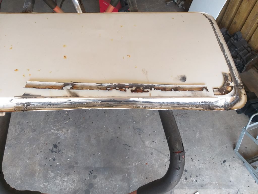
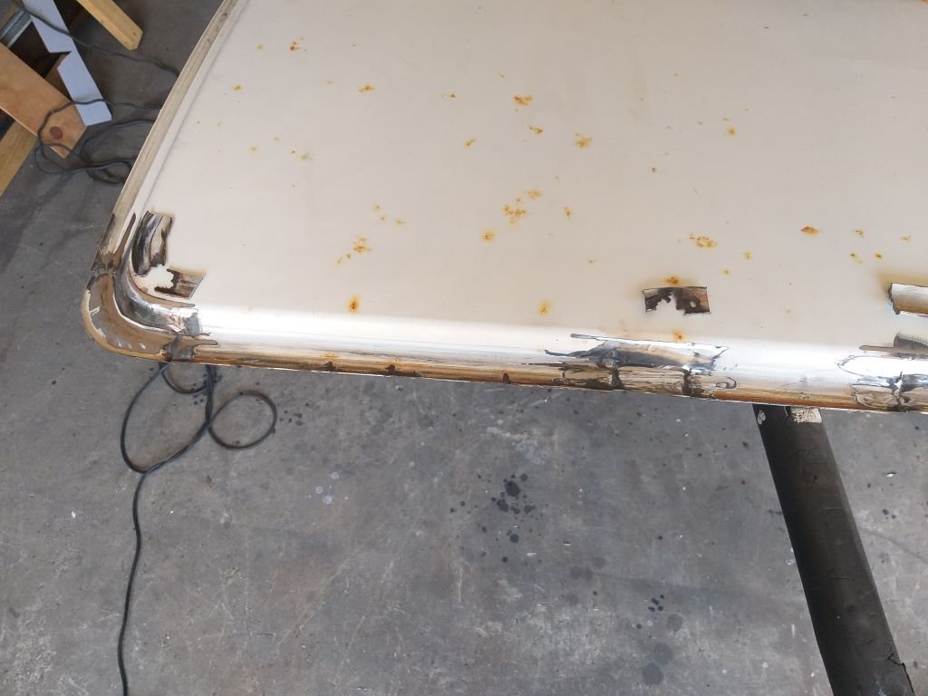
The poor old Bongo has spent the last few years living out in the elements, so she needs a bit of TLC before she goes on the market. The biggest job is resolving some rust that has crept into the edges of both side panels, so this morning I cracked into the first panel. A while back I replaced the panel in the sliding door with a window, so I was able to cut some patches from the spare which made the job a whole lot easier.
Cutty, cutty, weldy, weldy, grindy, grindy and I'm almost there. Just needs a bit of bog and a lick of paint and she'll be good to go.
-
10
-
Seeking advice - any input would be greatly appreciated.
Checking out the engine specs for the mighty Toyota 3Y engine, the factory thermostat opens at 85 degrees Celsius and they state that normal operating temps are anywhere between 85 and 100 degrees C.
Using a laser temp gun, I've been able to ascertain that at operating temp out on the open road the van runs a top of 97C measured at the thermostat housing (the last engine point before the cooling system). Idling in my driveway all day long I'm also measuring a top of 97C.
I don't know enough about Toyota engines to determine whether my current temps are too high, but it does make me nervous that I seem to be fairly close to the maximum temp stated by Toyota.
-
1
-
-
- Popular Post
- Popular Post
My mate Grant was giving his Mk2 wagon a bit of TLC when I dropped by his place yesterday.
-
16
-
- Popular Post
- Popular Post
Yesterday arvo I took the Thames through to town for its hot date with the wheel alignment machine.
As luck would have it the workshop was unusually quiet, so the whole crew gathered around for a bit of a nosey and the swapping of a few yarns.
I had visions of them telling me that everything was skewwhiff as I had used some pretty rudimentary methods to line up the front and rear units before welding them in. But by some miracle everything was straight and all that was needed were a few extra shims to get the LHS camber spot on and a bit of adjustment on the strut rods to get the caster where we needed it.
What a relief to have that job behind me.
-
17
-
Hiya All,
Is there anyone out there in old school land who is running a 3Y carburettor engine in either a Hilux or a Hiace and can check out the engine operating temperature for me with one of those laser type temp guns? I'd like to determine the temps on both the top water neck and the lower thermostat housing when fully warmed up.
I've tried Google but couldn't find anything and my workshop manual only provides the stats on the factory thermostat which fully opens at 85C.
Any help would be greatly appreciated. Ta in advance.
-
Mate, I am so chuffed for you. What a well-deserved outcome to an epic build. Happy motoring.
-
1
-
-
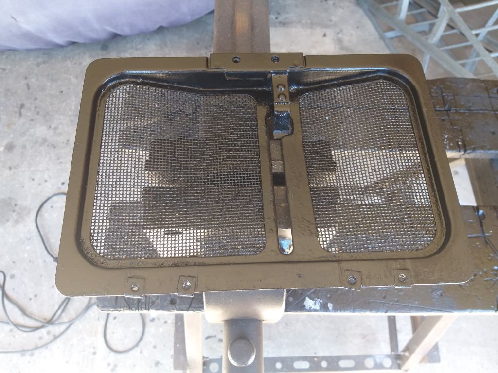
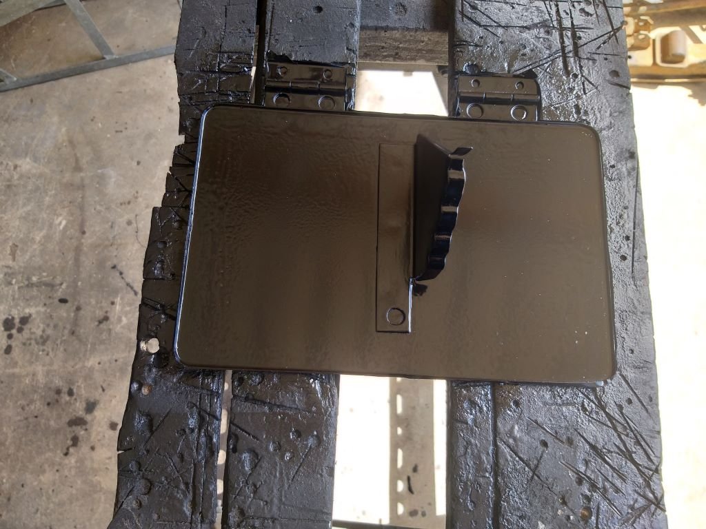
Jeez, the mesh in my little fresh air flap was a real bugger to paint. Even although I was applying really thin coats, I still managed to clog up a few of the gaps in the mesh. Was able to clear the holes with my thinnest bradawl, but it kept chipping the paint, so it took a few iterations of poking and painting before I was happy.
Doesn't look too shabby.
Popped it back in with some fresh stainless fixings and it should be good for another few years.
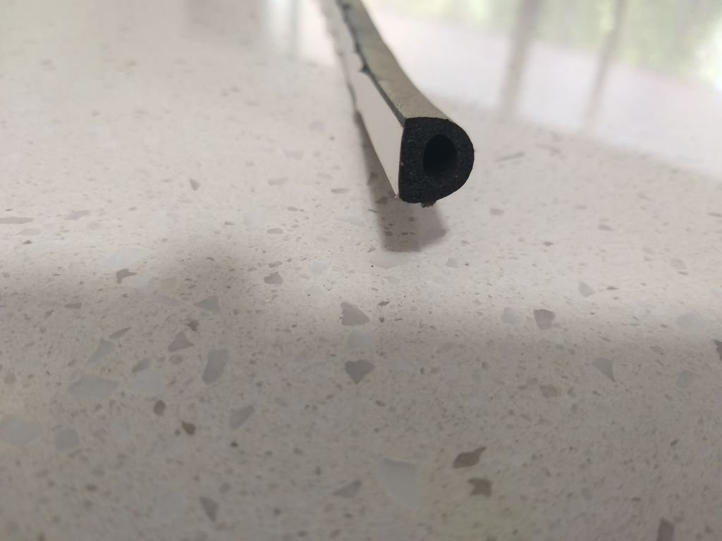
Oh, almost forgot to say that I found a perfect looking rubber seal in my stash to replace the sad looking cork original.
Unfortunately, I don't have enough to complete the job, so I'll grab some more from my local rubber place when I'm next in town.
-
9
-
-
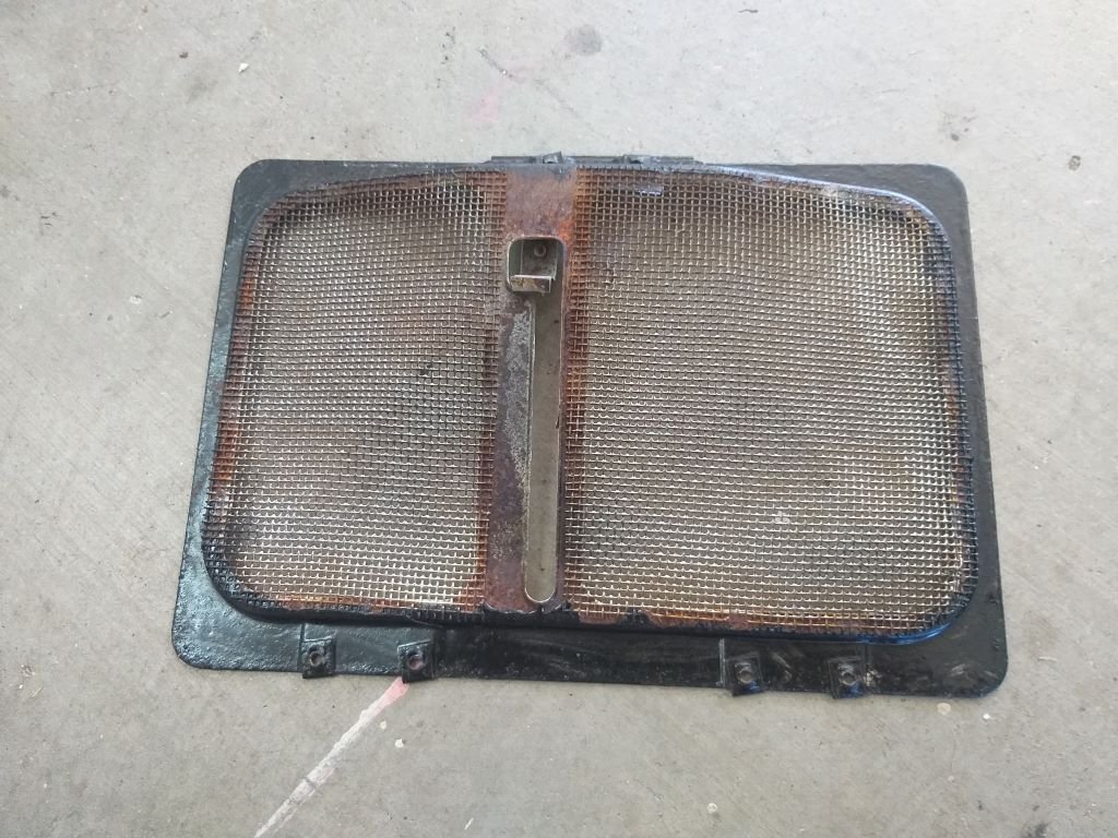
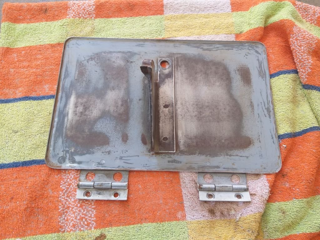
The mesh covered bit of my fresh air flap has been in the vinegar bath for a few days, but is still looking a bit grotty. The mesh looks a bit delicate so I'm loath to hit the thing with a flapper disk, but I did give it a light sand and then chucked some rust converter on the parts that look a bit dodgy.
While I wait for that to dry, I thought I'd move on to the next item on my snag list.
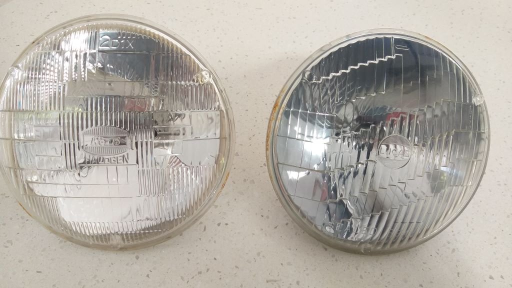
So, from day dot I've had issues with my left-hand headlight. At first I attributed the issue to a blown sealed beam - the one on the right in this photo.
A while back I fitted a new set of H4 units with LED globes, but was still having issues with both lights staying on high beam no matter what position the dip switch was in.
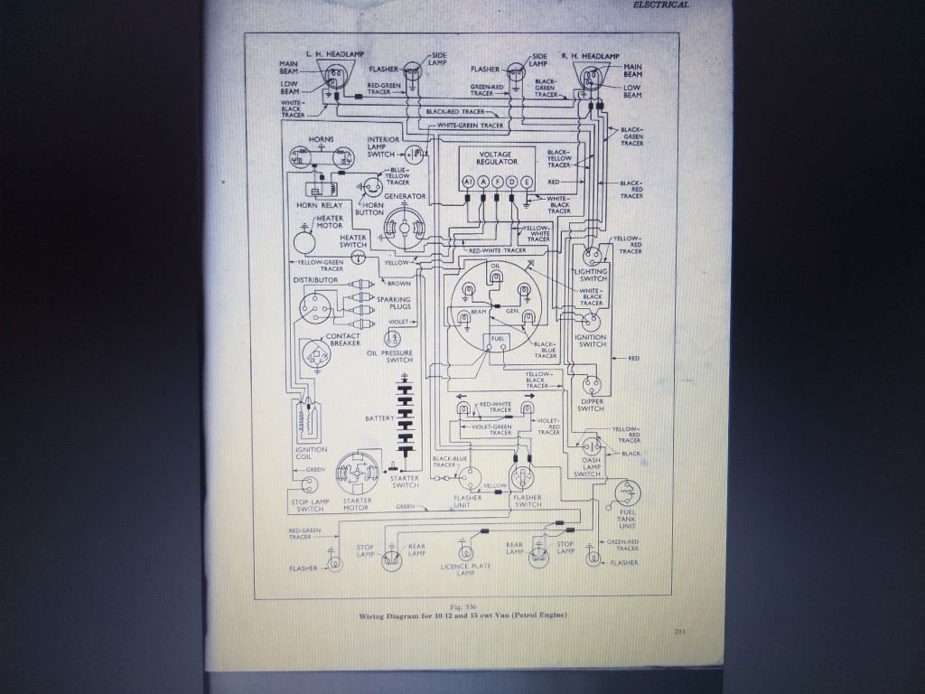
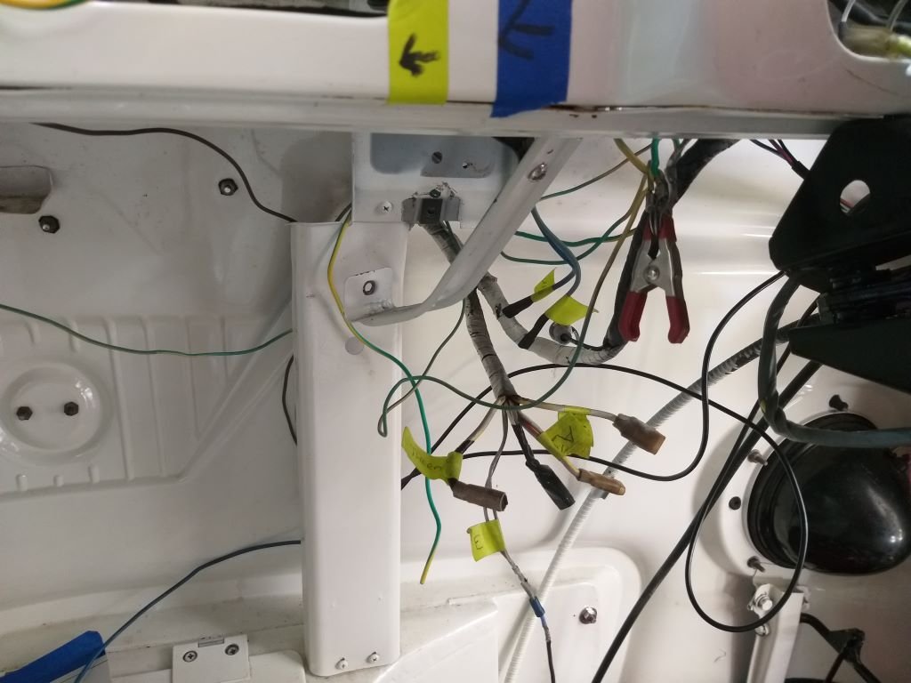
So, first thing this morning I dusted off my copy of the factory wiring diagram and cracked straight into tracing the issue.
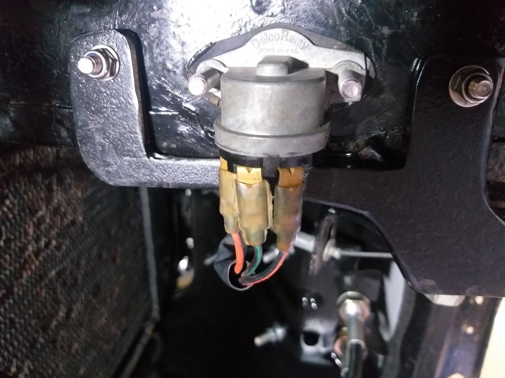
Thought I'd start off by looking at the dip switch. This is a new unit that I fitted a while back.
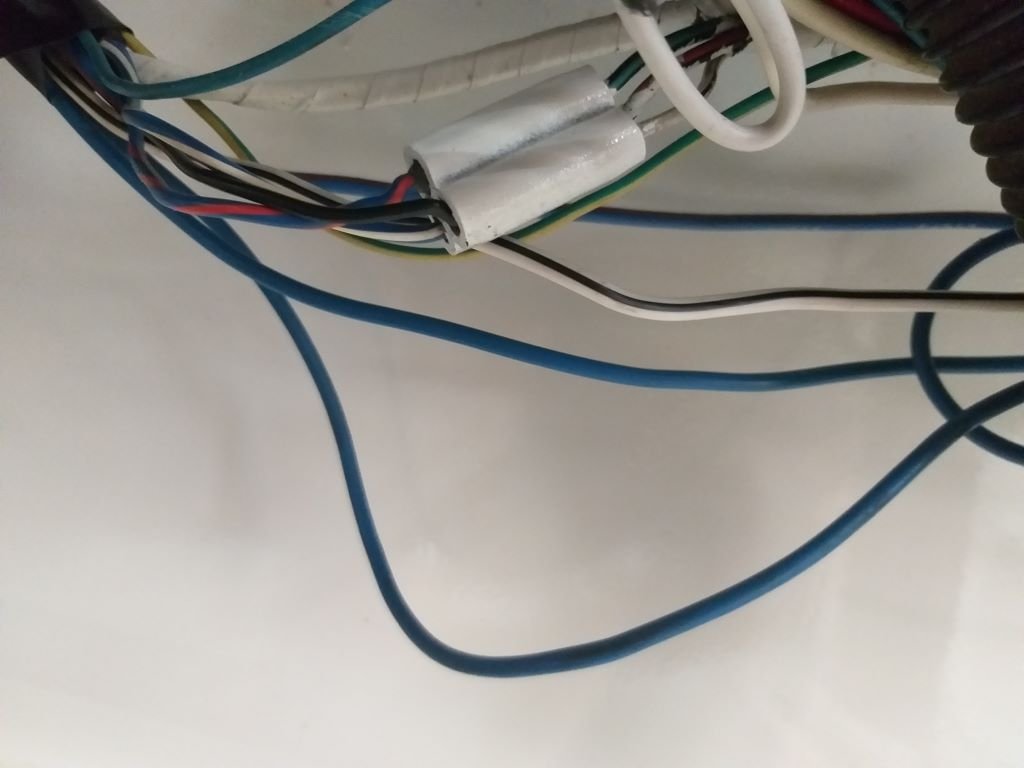
Popped both headlights out and did a continuity test on the wires running from the dip switch to each headlight. Quickly found an issue with the low beam wire on the left-hand headlight. No power getting through.
Grovelled under the dash and discovered that someone had swapped the earth and low beam wires around on the little inline connector. I suspect this happened when the painters re-installed the headlights after the bare metal restoration. Easy enough to do especially with all the overspray that the mucky buggers had got on the main wiring loom.
Anyway, with that sorted I've ticked another item off the "to do" list.
Thanks for looking.
-
8
-
-
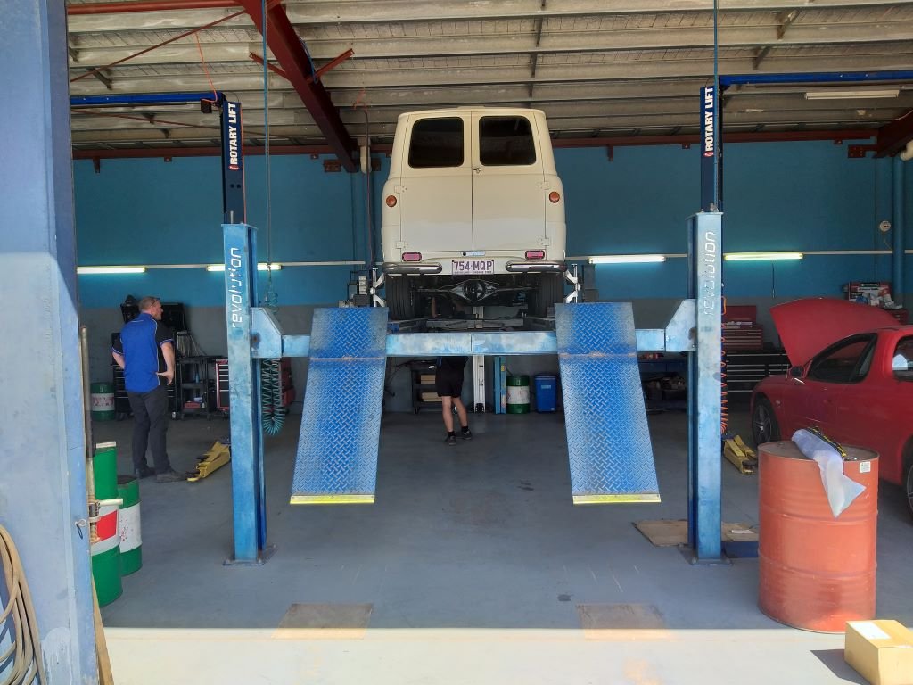
Yesterday I took the Thames through to my mate Grant's place. I've been having a problem selecting 5th gear and figuring out what is wrong is a two person job, so Grant being the GC that he is stuck his hand up to help. We chucked the thing on his 4 poster and I worked the gear shift while he checked out what was going on. Turns out that the angle on one of my morse cable holding brackets was slightly off thus causing the inner cable to snag up when trying to select 5th. I elongated one of the mounting holes on the bracket to change the angle whilst Grant painted the fender on a customer's Holden and we then headed out for a test run.
Learnt a few things during that drive. Firstly, my new Speco temp gauge is reading high by about 7 degrees C according to Grant's laser temp gun. Secondly my fuel gauge is pretty accurate in that when the needle is on empty the tank is actually empty. Oops. Luckily another mate of ours saved us from a long walk home by riding to the rescue with a can of fuel. I certainly won't be making that mistake again.
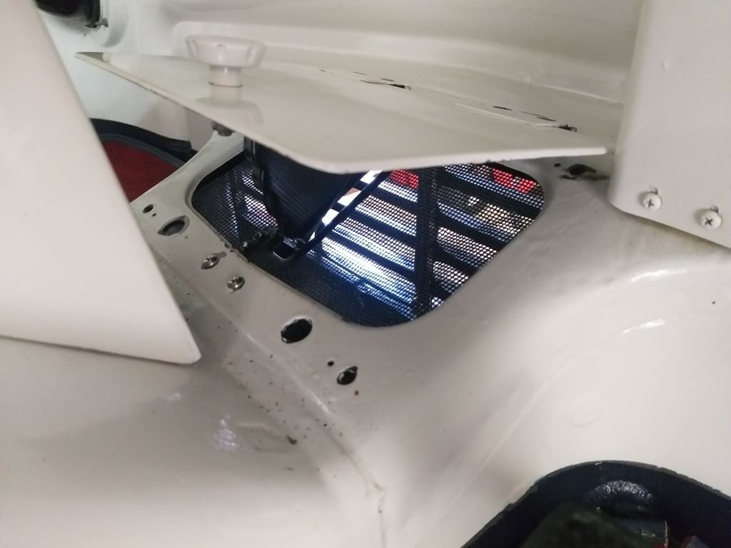
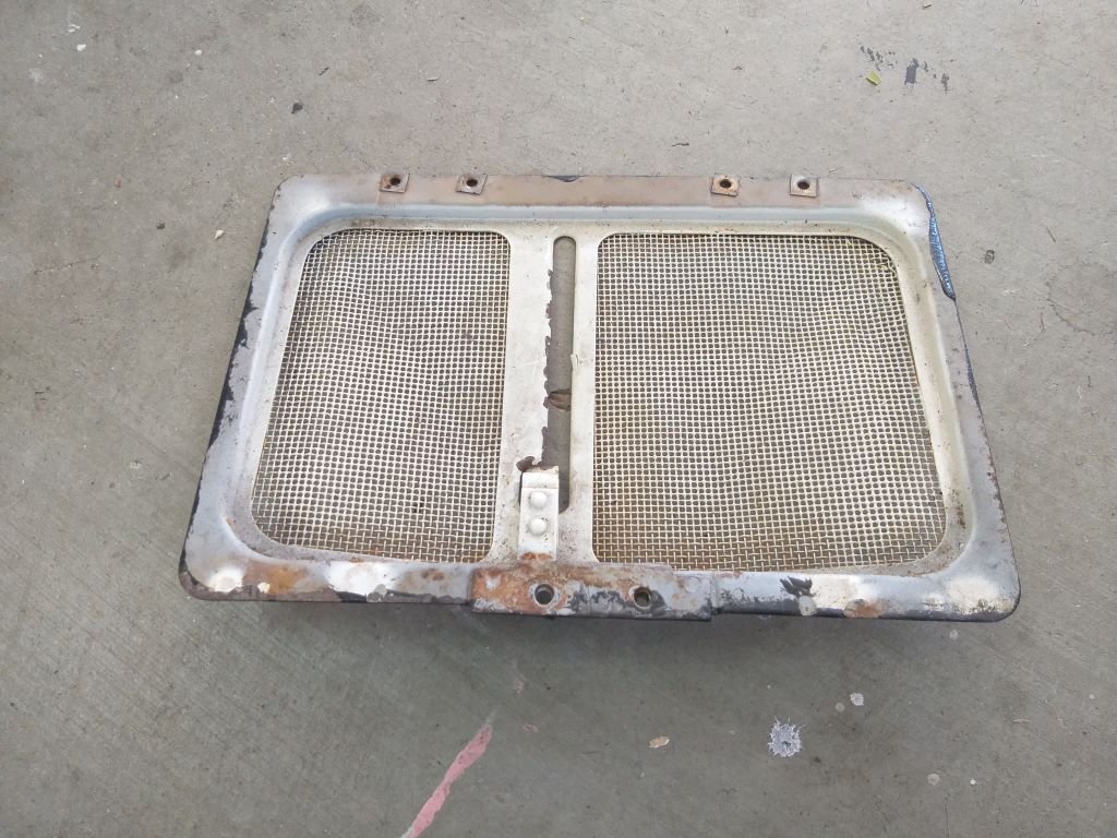
Anyway, today I thought I'd turn my attention to my much-neglected fresh air flap. Originally this was going to be replaced with my home-made a/c evaporator unit, but since that plan has been shelved, I thought I'd give the flap a birthday.
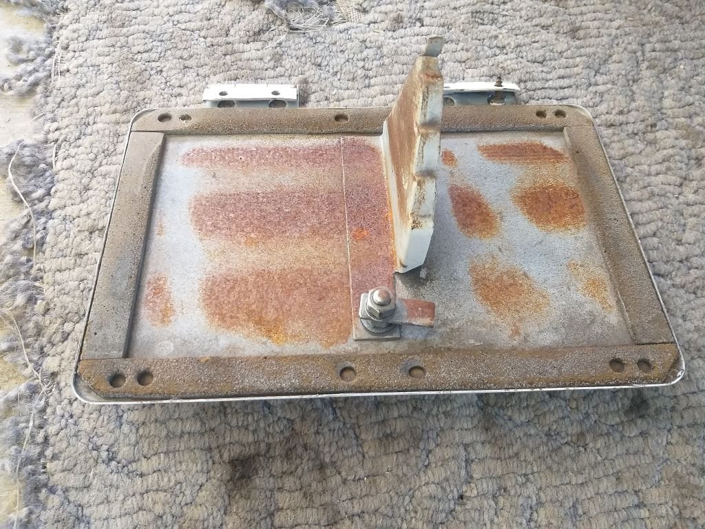
The flap mechanism is made up of two components. The underside is a meshed insect / stone guard that was looking pretty second hand. The top is covered in overspray and the bottom is sporting a mixture of surface rust and freshish chassis black from when I did the underside.
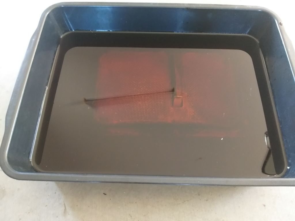
Started off by dropping it into a vinegar bath where it will languish for a day or two.
The actual flap door looks really good on the cabin side, but not so good underneath.
The cork seal was far gone so I scraped that out and then sanded down the surface rust.
A bit of primer and a few coats of satin black and it's looking a bit better.
More tomorrow.
-
9
-
-
- Popular Post
- Popular Post
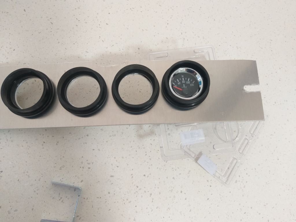
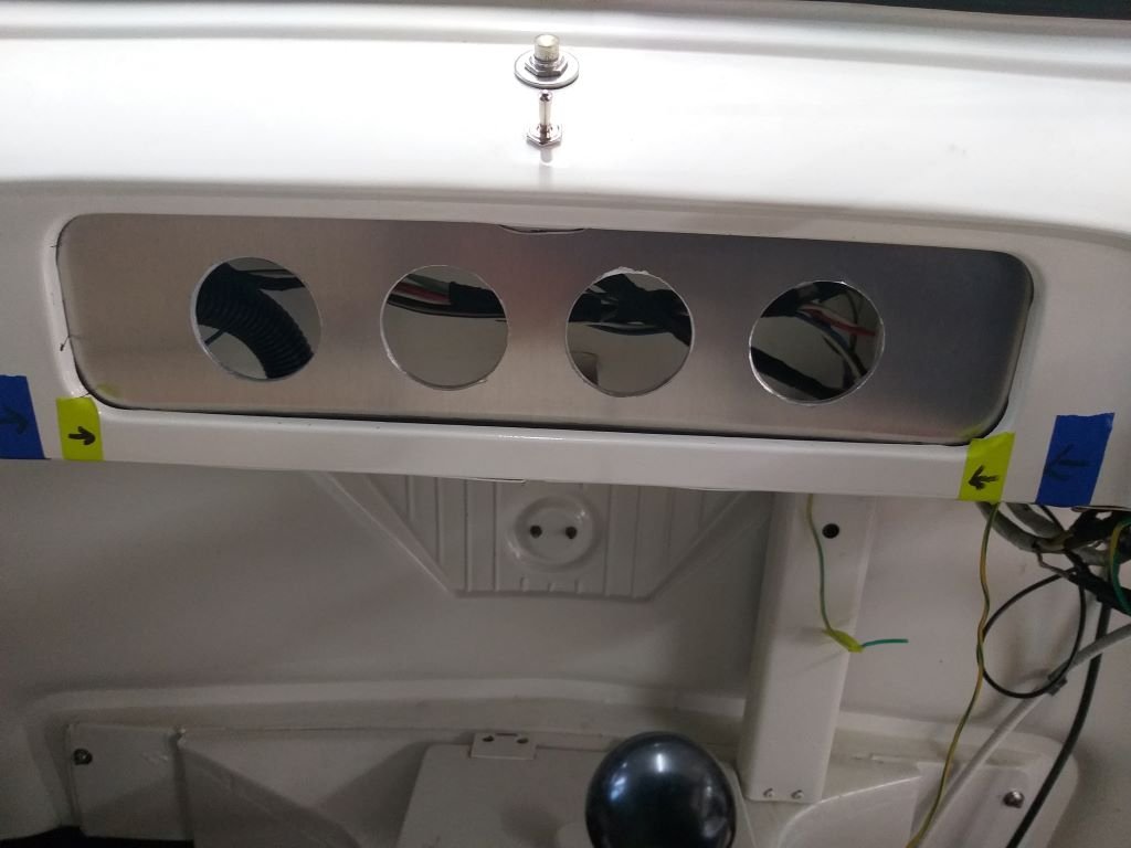
Managed to centralise the gauge cluster in the opening by moving the mounting holes in the side brackets.
Then I turned my attention to each individual gauge pod and how exactly I'm going to fix the gauges in them. Since the back of each pod is completely sealed the usual U shaped fixing brackets that come with most 2-inch gauges won't work.
A set of instructions would have been nice, but I guess I bought the economy version so no such luck.
At first I thought that the gauges might just be a press fit, but upon sliding one into the pod the gauge is loose as, so that can't be the answer.
Going through the bits that came with each pod there seems to be a few strips of double-sided tape. Surely, they aren't expecting me to fix the gauge into the tube with that are they?
Asked my mate Google, but couldn't find anything useful, so figured I'd just do my own thing.
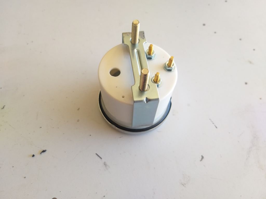
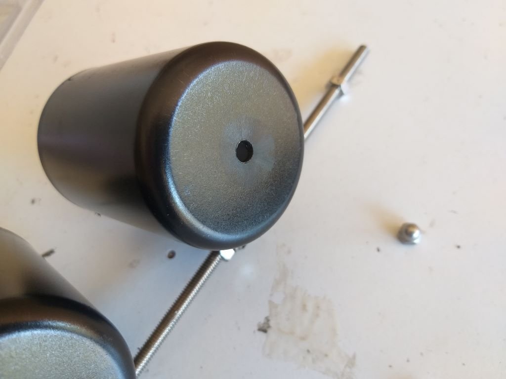
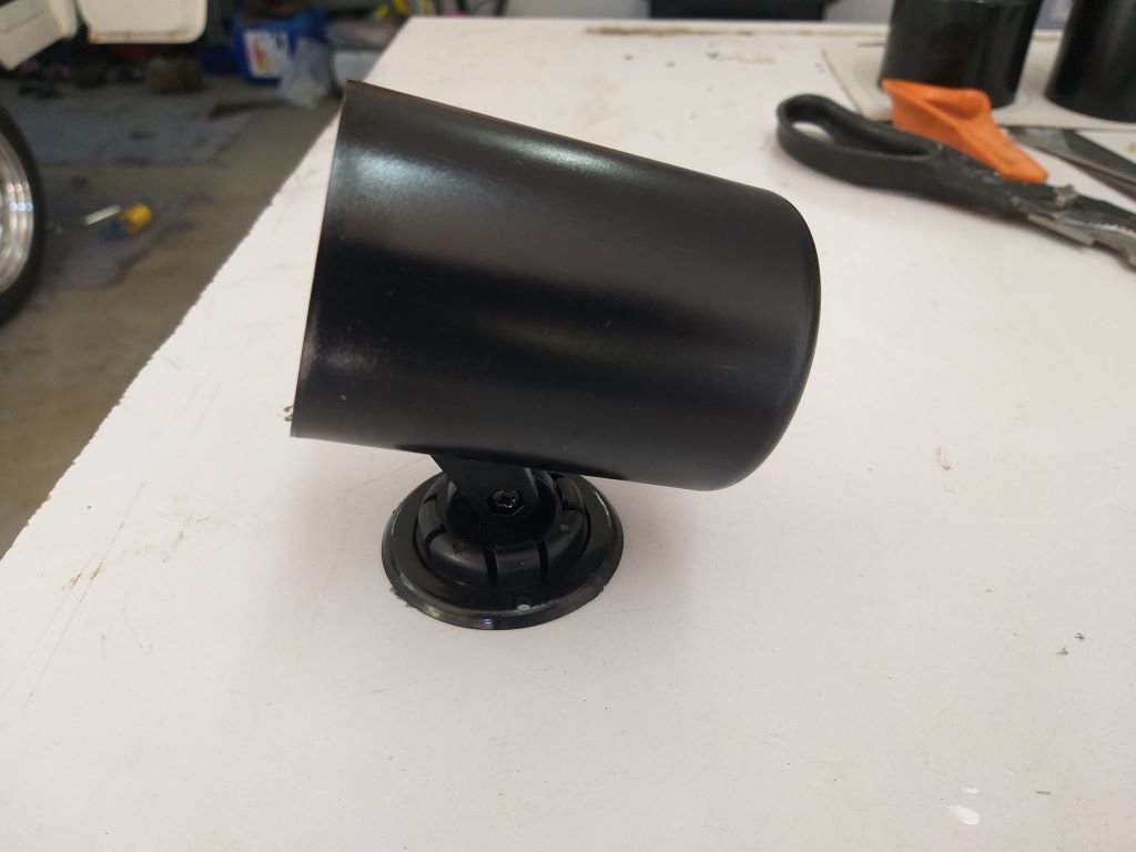
So first up I poked a hole in the rounded end of the pod. The little factory dimple made it such that even a rough bastard like me managed to get the hole centralised.
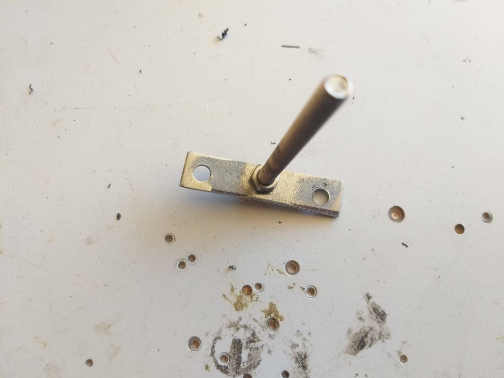
Then I trimmed a little metal offcut to size, poked a few holes in it and made this little doohickie:
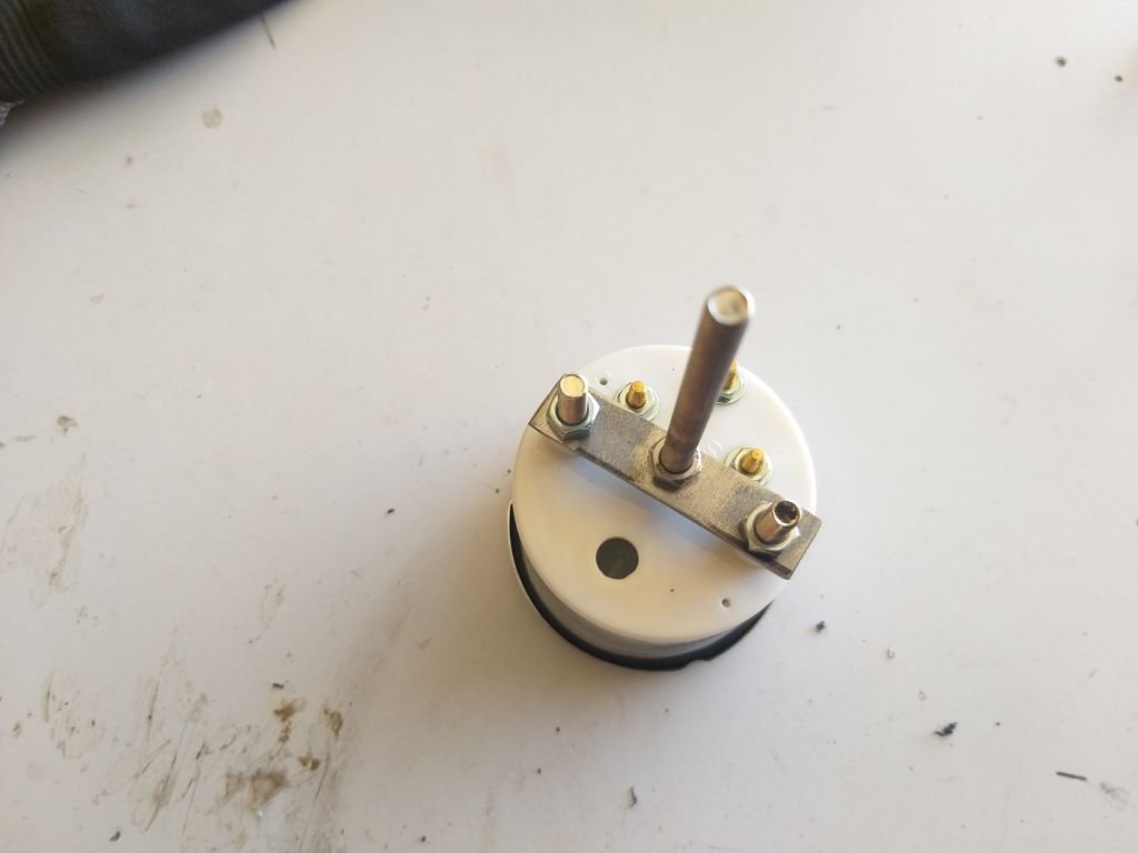
Slapped it onto the back of the gauge like so:
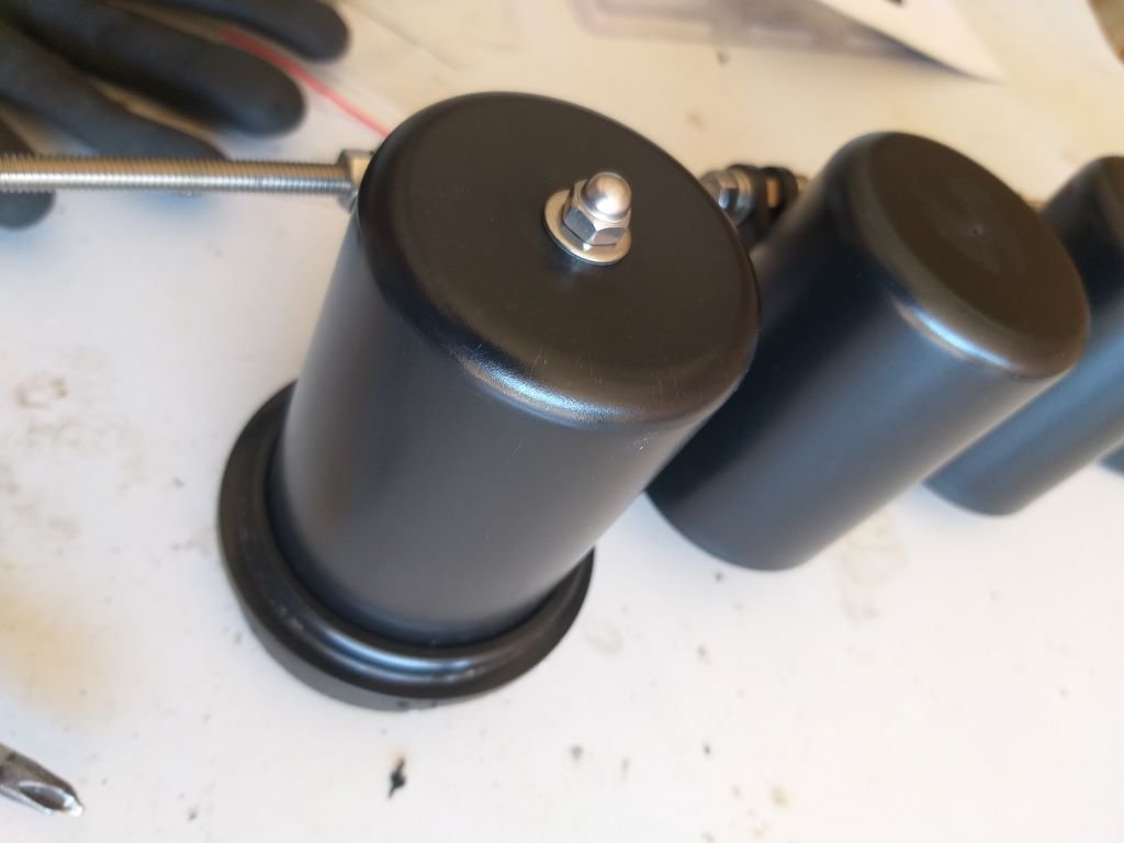
A quick test fit and I even went as far as fitting a lush looking stainless steel domed nut.
Next step is to tidy up the little bracket and give it a spritz of paint.
Repeat times three and I'm home and hosed.
-
14
-
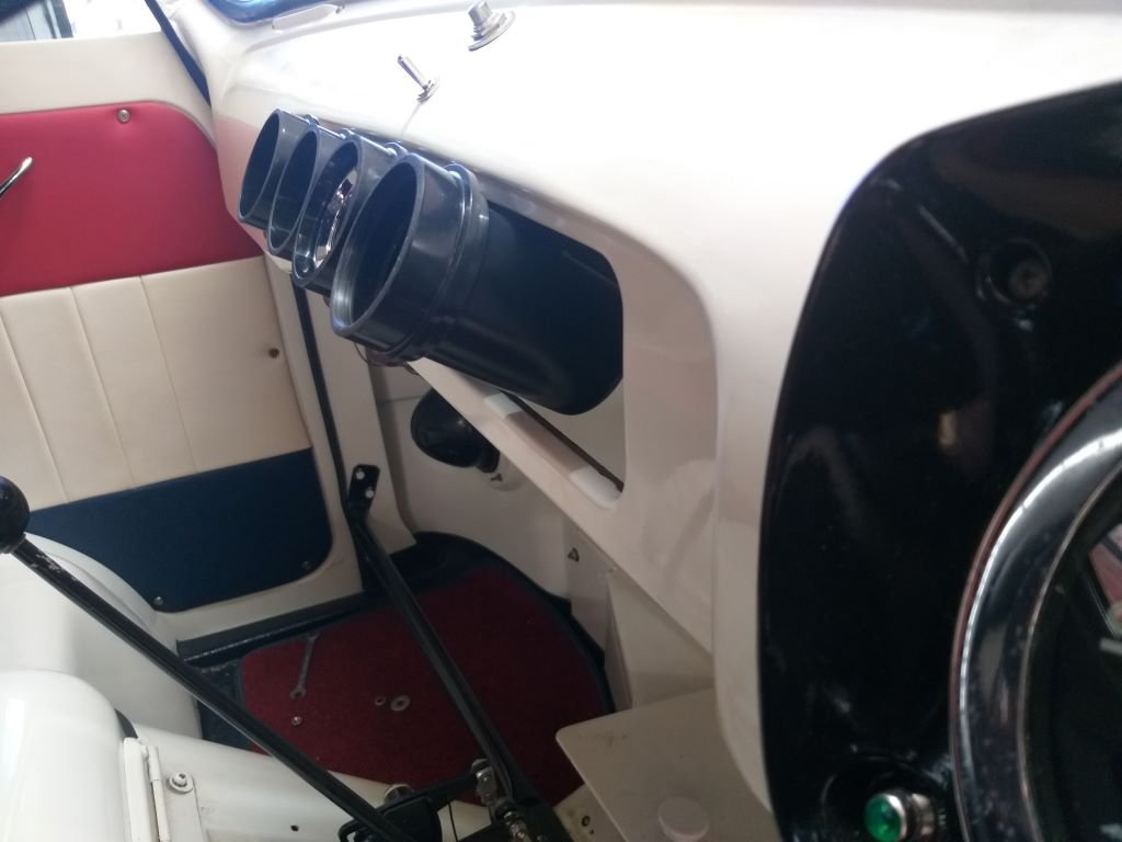
It's Thames day 601 according to the Captain's Log and I thought I'd spend it by building another iteration of the gauge panel.
As mentioned yesterday, the current angle of the gauges makes them very difficult to read from the driving position, so I figured that a little angle was called for.
First step was to banish the aluminium filler panel to the naughty corner and figure a way to angle the gauges.
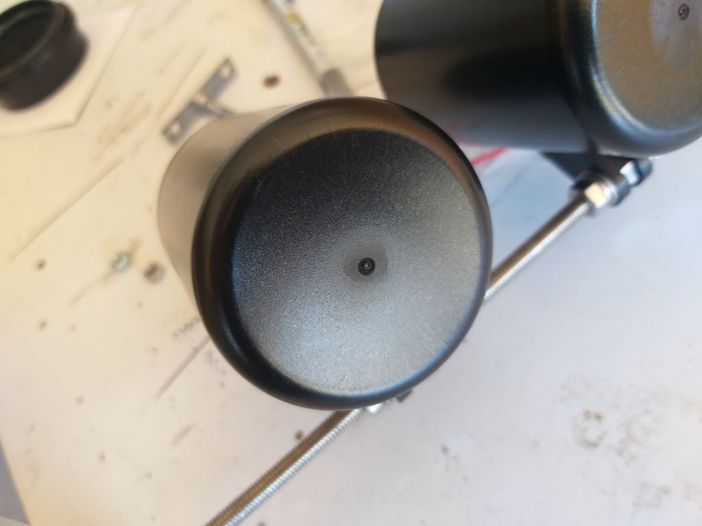
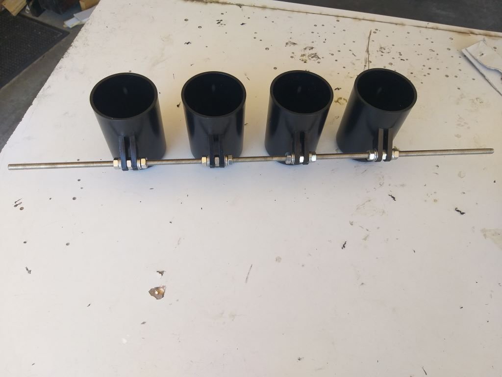
Started by blowing the dust off the cheapie individual gauge pods that I bought a while back:
Stripped the mounting feet off the buggers and attached them together with a bit of threaded rod, some nuts and washers like so:
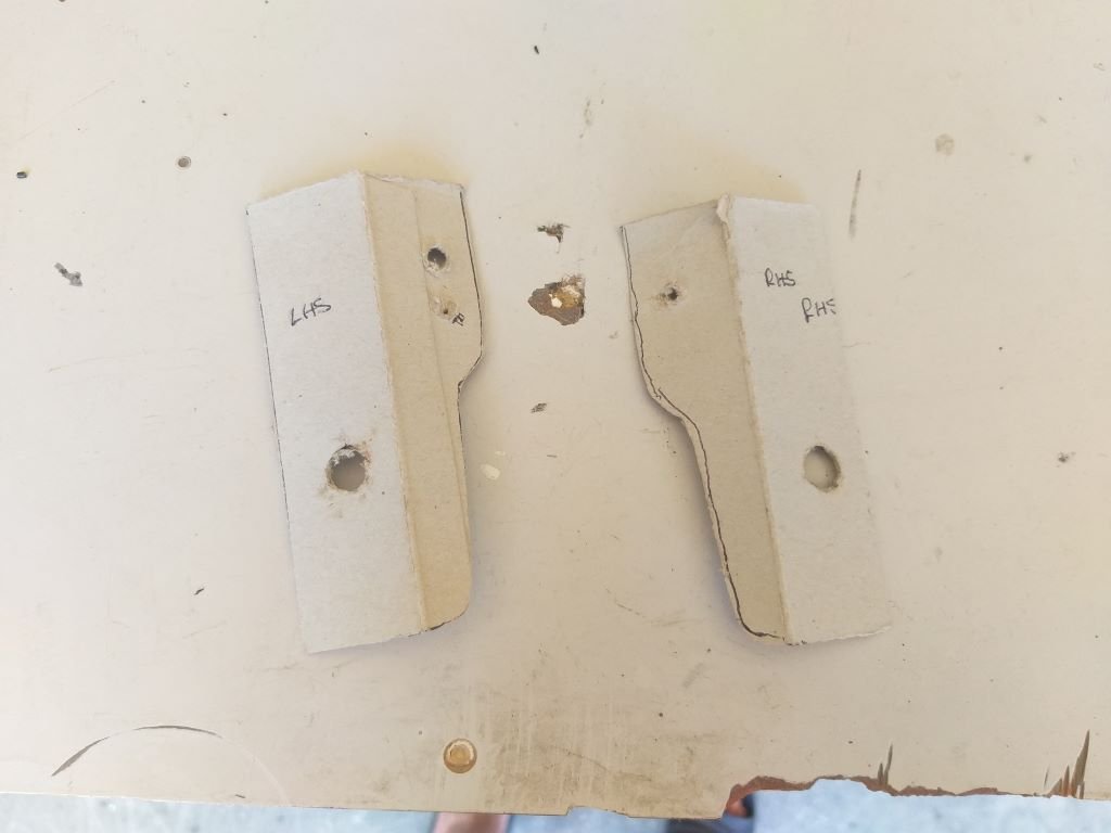
Whipped up some dodgy looking templates for a set of mounting brackets that will attach the threaded rod to the bolts that I glued to the back of the dash to hold my original gauge panel.
Carved some replicas out of some angled aluminium off-cuts, poked a few holes and bolted things into position.
Doesn't look so great in the above photo, but the gauge visibilty is perfect from the driving position.
The next photo shows a side view and clearly shows the angle of the new setup.
As you can see in the above photo, I'm still using the slip collars to give the gauges that countersunk look.
I want to drop the pods slightly to get things more centralised in the opening, so I'll fine tune the mounting brackets tomorrow.
Then all I need to do is figure out how I'm going to build a backing plate to neaten things up.
Thanks for looking.
-
8
-
-
- Popular Post
- Popular Post
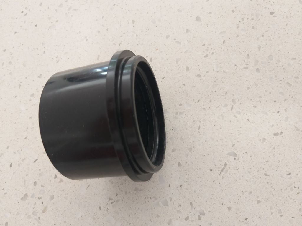
Next step on my gauge panel is to trim my plastic surround rings down to the correct length.
Scratched around my tool collection for something appropriate but I figured that using a cut off wheel or hack saw just wasn't going to give me the finish that I am looking for, so time to call in some professional help.
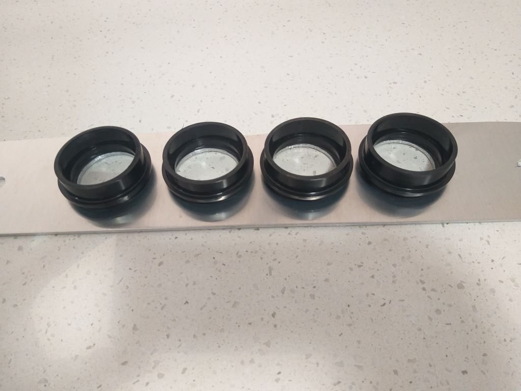
My "go to" general engineering shop in town closed down a while ago so I've been asking around to see if anyone could recommend another crowd. Then a mate of mine suggested that I head along to see the Barrys that hang out at the local Men's Shed. It's only about 5km from home so first thing this morning I hopped in the Moke and headed on down. Gotta say that I was really blown away by the equipment that these old blokes have at their disposal. Hooked up with a really nice bloke called Stuart who chucked the rings on a wood lathe and in next to no time I had these perfect specimens:
And all for the cost of the equivalent of a few beers. AAA+++ would happily trade again.
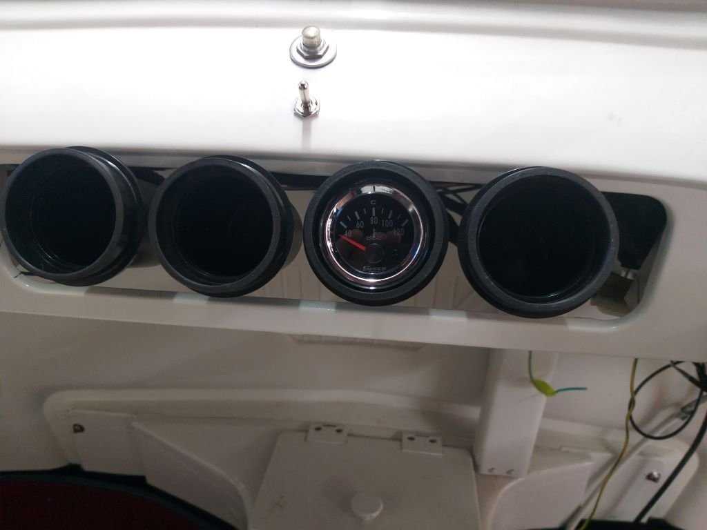
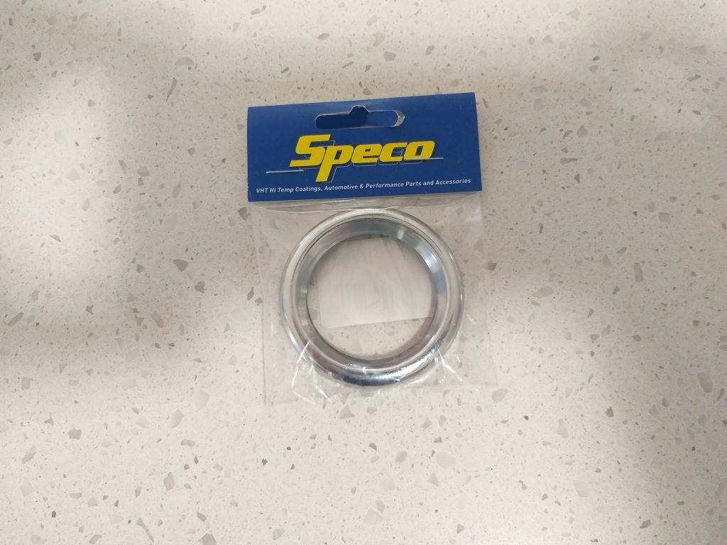
So, from a gauge perspective I'm going with Speco units cause cheap and cheerful. Their Street Series have the black face that I am looking for and they also supply chrome snap on trim rings for those wanting that old school look.
A few weeks back I ordered one of their water temp gauges as a starter for ten.
Now with the surround rings ready to go I clipped on the trim ring and mounted the gauge on the panel just to get the feel.
Noice !
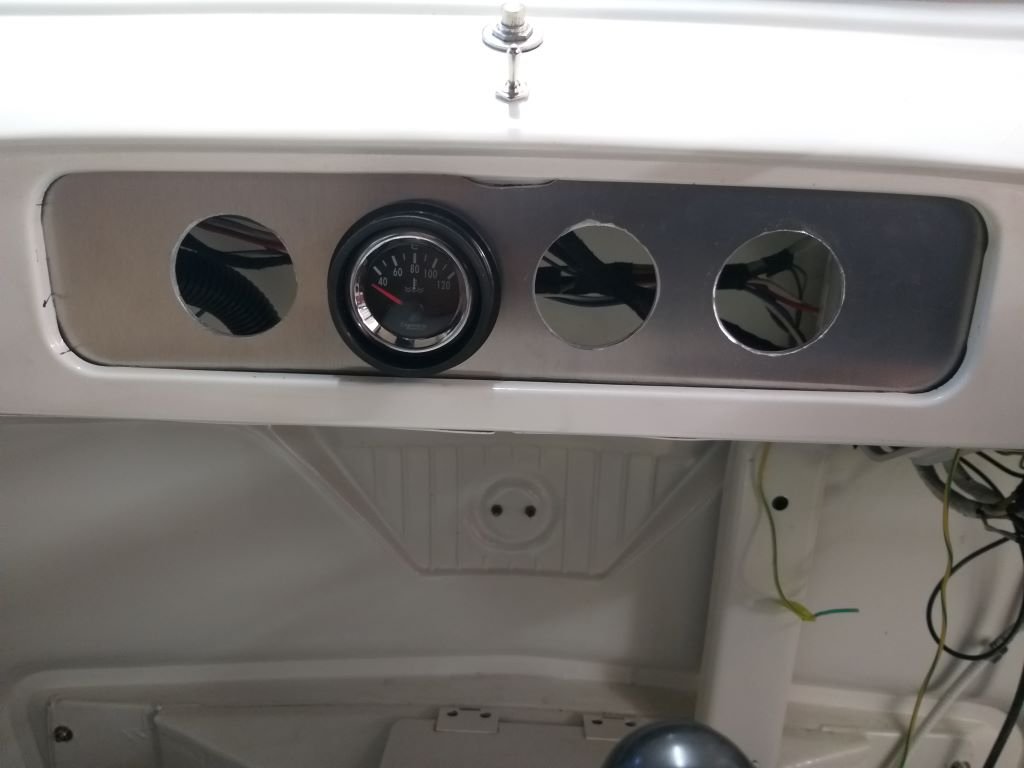
Flushed with success I headed over to the Thames and quickly chucked the panel in.
And, whilst I'm happy with the overall look the jury is still out on whether this is going to work as well as I envisaged. Reason being that the angle that the gauges sit at in the panel makes them quite hard to read from the standard driving position. If they were tilted a bit up like the factory speedo is they would be perfect.
So, I need to come up with some kind of wedged shape intermediate panel that will provide me with the angle that I need.
Gonna have to give some more thought to how I'm going to achieve this.
-
10
-
- Popular Post
- Popular Post
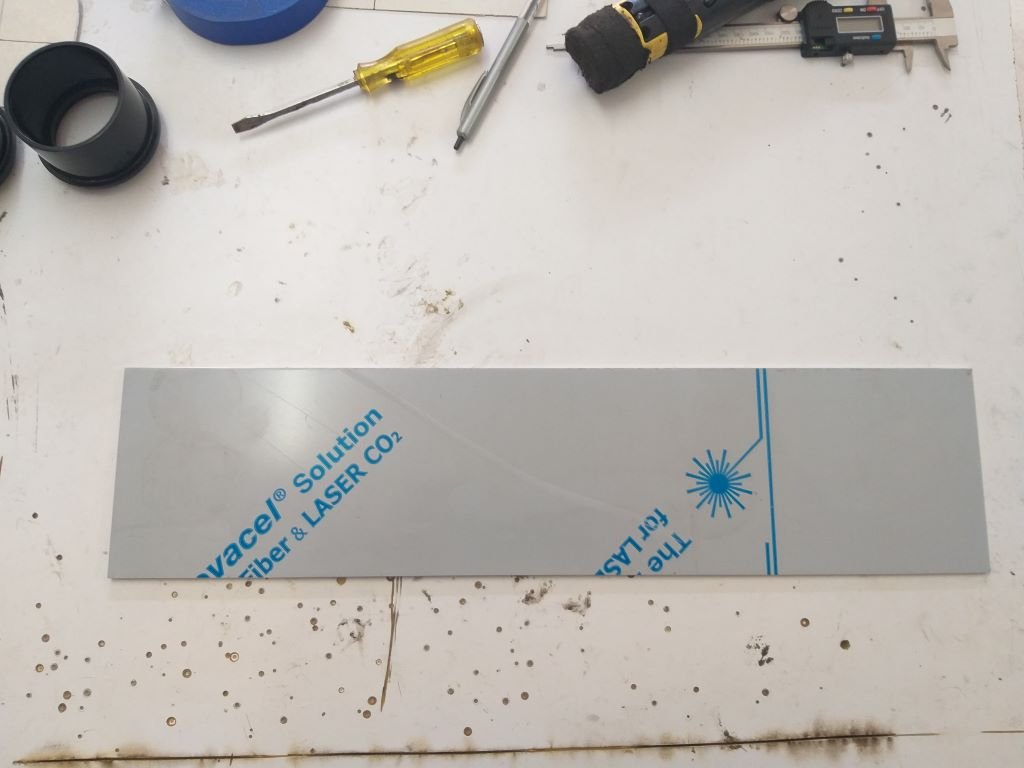
It's time to build the new gauge panel that I was talking about a few weeks back.
My mate Cameron kindly supplied me with 3 aluminium offcuts thus giving me an opportunity to make 2 cock ups before I get things right.
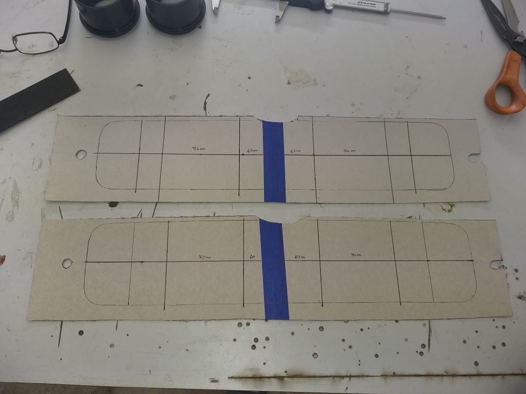
First step was to make a cardboard template.
I needed to join two cereal box sides together to make a piece long enough hence the dodgy looking tape joint.
The next step was to work out the gauge spacing. First time I used a spacing of 86mm between gauge centres, but it looked a bit odd, so I reduced the spacing to 80mm which I am much happier with.
I had to create a little crescent shaped notch in the top of the template in order to clear the steel tab in the dash for the latch on the hinged glove box lid that were factory fitted to the bus versions. I've had to slot the mounting hole on the right hand side as there is only a thin gap between the back of the dashboard panel and the wiper motor.
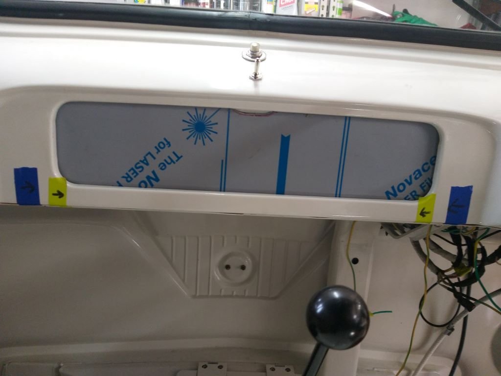
Carved up my first piece of aluminium and chucked it in for a test fit.
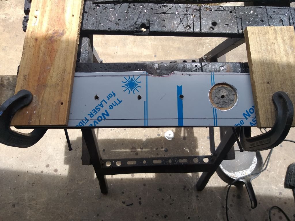
Then took to it with my hole saw:
Had to pace myself with the drilling as I didn't want to overtax my little Ozito battery drill.
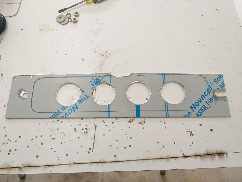
Eventually ended up with this:
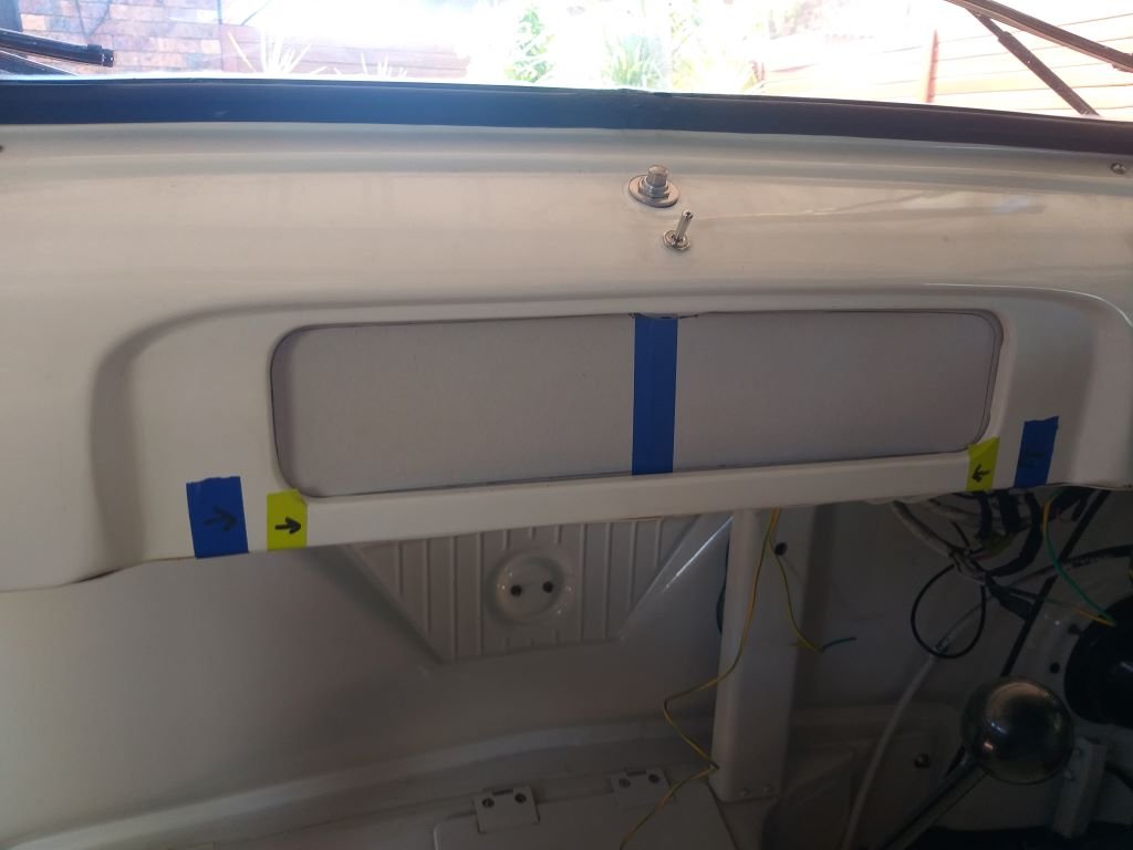
Gave it a quick test fit.
Not bad, but I'll need to put some shape in it as the dashboard has a slight curve.
More tomorrow.
-
10
-
- Popular Post
- Popular Post
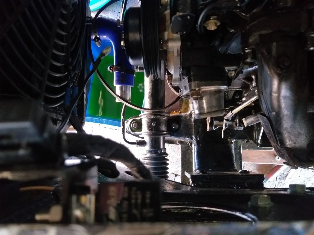
Finally finished off the wiring yesterday and took the van for its first drive with the new Astra power steering pump. I'm chuffed to report that it works really well.
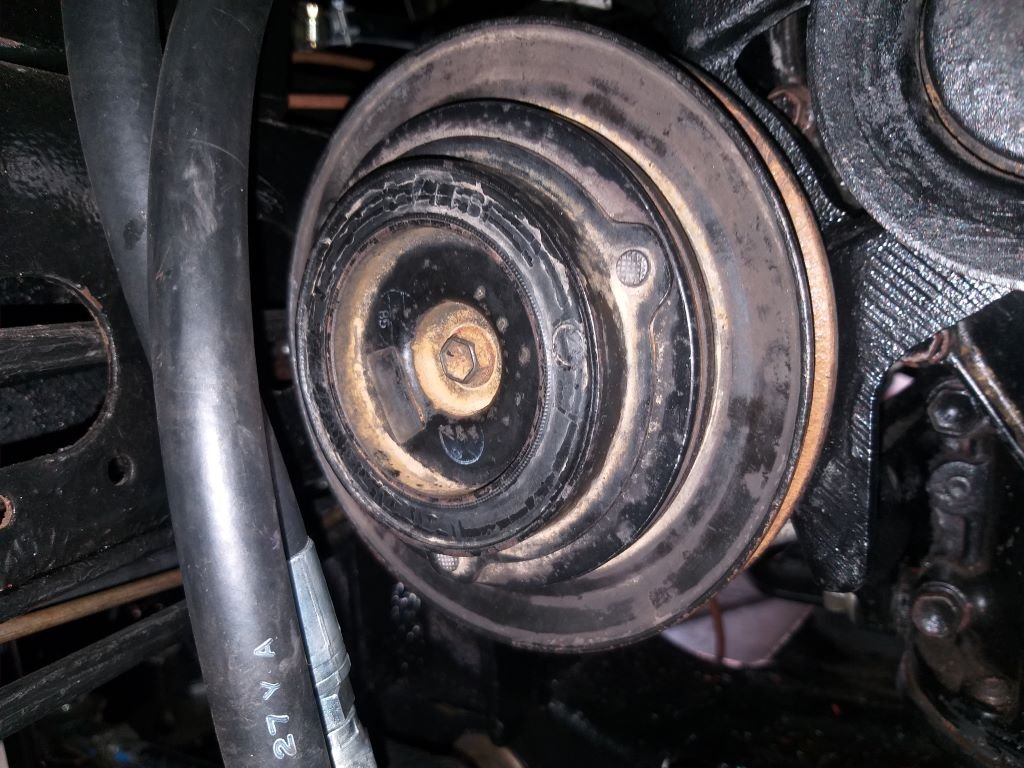
We ended up taking the van for our usual Friday night burger cruise which highlighted a few extra items that needed adding to the snag list. The most urgent one being an intermittent belt squeal. To be honest this has been lurking around since day one and up to now I've just been masking the issue with liberal applications of soap. I was hoping that the belt driving my original power steering pump was the culprit, but now that this is no longer, the squeal persists, so must be the alternator belt.
So, first thing this morning I took a closer look. Belt tension looked good, but focusing closer on the belt alignment I noticed that the alternator was sitting a smidge too far forward.
Things are so tight in the engine box that to get the alternator out you need to drain the radiator and remove the lower radiator hose, which leaves just enough room to turn the alternator on its head and wrestle the bloody thing out.
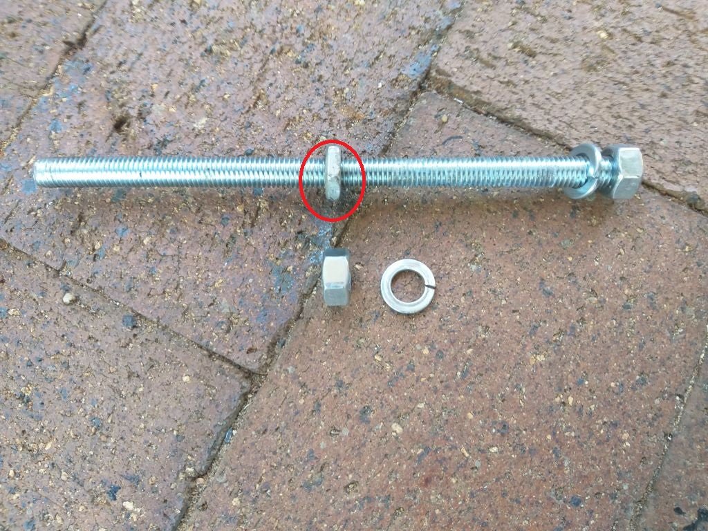
I'm using a reverse mounted 3Y alternator bracket with a piece of threaded rod that acts as the through bolt. A standard nut and spring washer on either end fix the threaded rod in place, so the simplest way to sit the alternator further back without modifying the bracket is to reduce the thickness of the front nut. Scratched around in my box of spare nuts and was lucky enough to find a narrower nut with the correct thread.
Chucked the alternator back in, but it was still a fraction too far forward so I ended up ditching the front spring washer, which made things perfect.
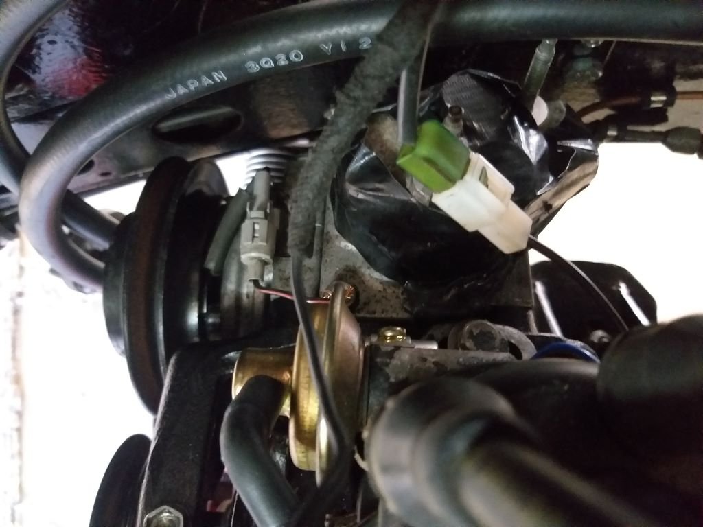
Should be okay as I still have a spring washer on the rear nut.
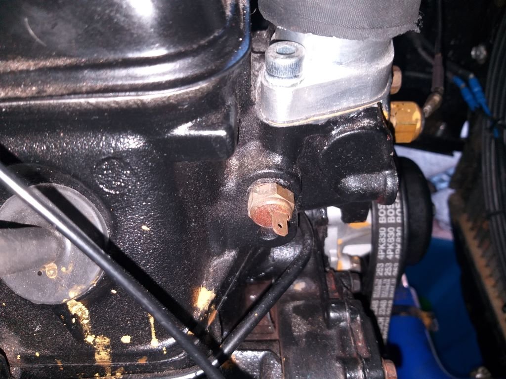
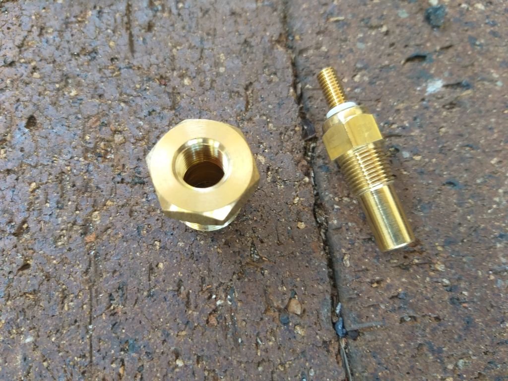
Before re-filling the coolant, I took the opportunity to replace the factory temp gauge sender unit with the new sender for my aftermarket gauge.
Old:
New one with correct adapter:
All sorted and ready for the fitting of the gauge.
Thanks for looking.
-
10
-
It's almost two weeks since my last Thames update and I'm embarrassed to say that I am still mucking about with wiring.
Whilst grovelling around under the dash wiring up my power steering pump it dawned on me that now that I have changed direction in terms of the style of the internal aircon unit that I am planning to fit, I'm no longer going to be able to access the new fuse blocks that I mounted earlier in the piece.
So with no choice but to re-do the job, I disconnected the wiring and removed the fuse panel. Luckily, I hadn't yet re-wrapped the harness.
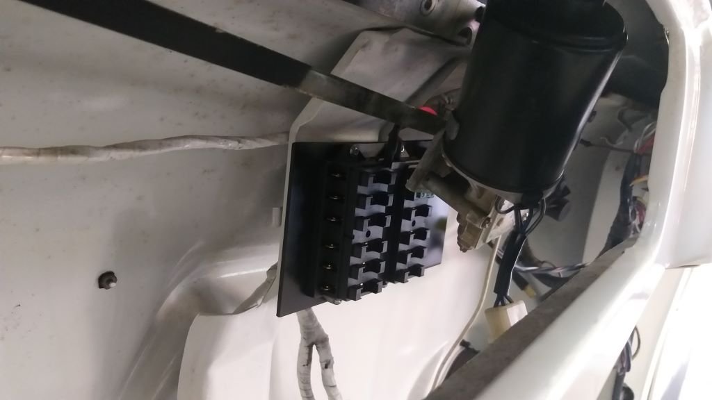
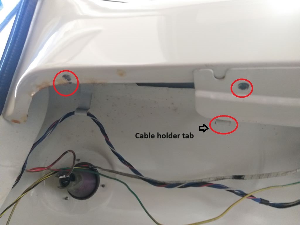
Looked around for an alternative location for the fuse panel that will be well out of the way and decided to tuck it up under the dashboard on the passenger side.
Found two existing mounting holes in the dash lip and figured I might be able to attach the opposite side of the panel to one of the metal cable holder tabs that is welded in place.
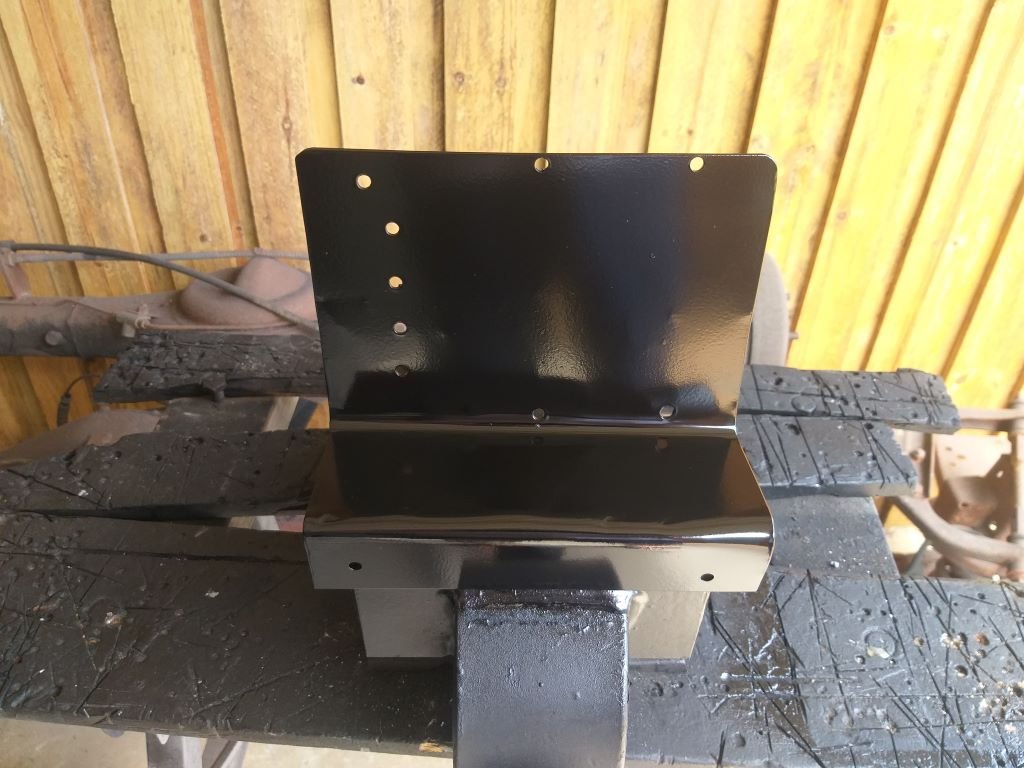
After some fiddling about with a cardboard template, I bent up some metal plate, poked a few holes in it and gave it a spritz of the usual satin black.
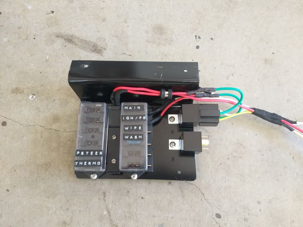
Let things dry off overnight, then transferred the fuse blocks and relays across from the old panel.
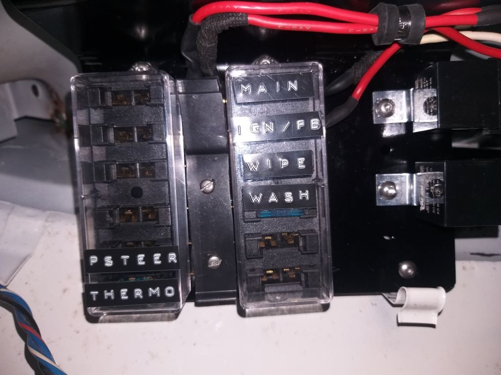
I had to replace the wires for the main fuse as the originals were too short, but with that done I was able to mount the panel in his new home. A bit tricky wedging myself under the dashboard to take a photo for you, so apologies for the quality, but you get the idea.
And now I'm so looking forward to extending the rest of the wires to the new panel location.
Not.
-
8
-
-
- Popular Post
- Popular Post
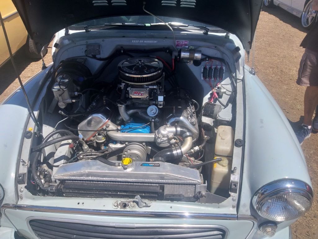
Saw this Morrie at a local car show yesterday. Guy had stuffed a V8 Daimler engine into it. Thought I'd post this for @tortron and the rest of the Morrie foamers.

-
11
-
2


Flash's 1965 Ford Thames
in Project Discussion
Posted
Thanks for the feedback @Tiger Tamer. Yep super chuffed with how it has turned out