Flash
-
Posts
1,719 -
Joined
-
Last visited
-
Days Won
2
Everything posted by Flash
-

Discuss here about Yoeddynz's little Imp project...
Flash replied to yoeddynz's topic in Project Discussion
Absolutely epic Alex. Well done mate! -
Long time no update on the old Mustang so here goes: So, the EFI was working like a champ and then it wasn't. All of a sudden, no start, just puffs of black smoke on cranking and a strong smell of fuel. Checked the pressure gauge on the little swirl pot. Fuel pressure was building up normally on ignition but dropping to zero on cranking. Pulled the air cleaner and she was dumping fuel like no tomorrow. Faulty injector methinks and of course the system was just out of warranty. Must say that I'm a bit over this system, just too temperamental in my opinion. Pulled it all out over the weekend and chucked it on Marketplace at a hugely discounted price, just to get it out of my sight. 944 clicks later and the system has just headed off to its new owner in Victoria. I was totally honest with him about the issues, but he seems unfazed, so I've got to admire his bravery. So, it's off to the dark side for me with a refurbished Holley 450 CFM featuring sometime in the near future.

- 198 replies
-
- 13
-

-

-
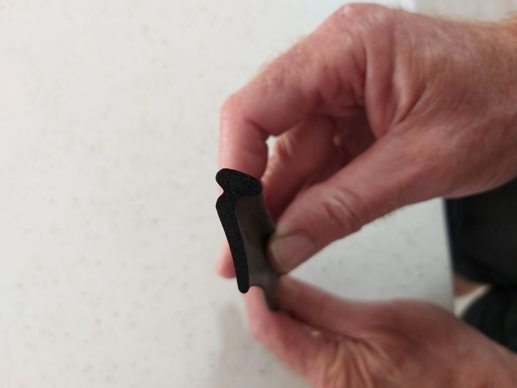
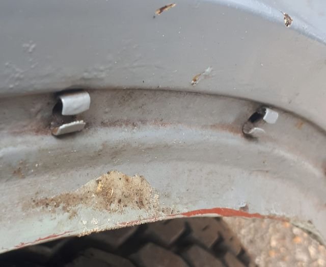
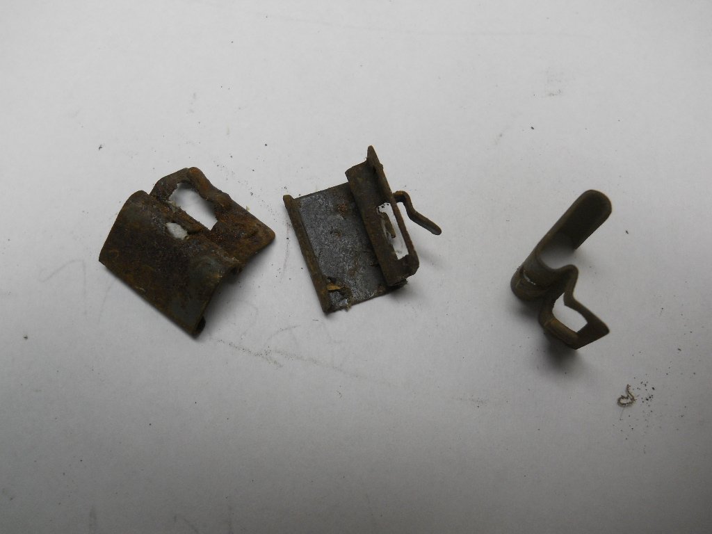
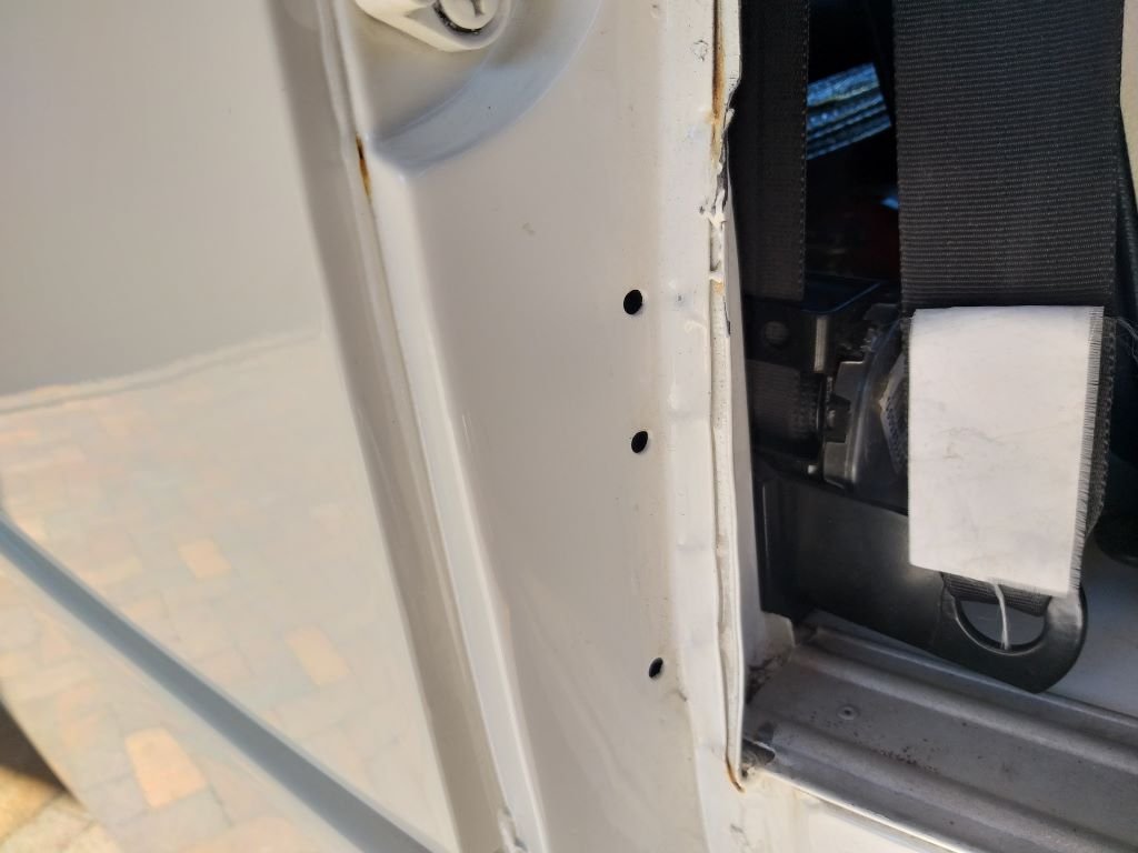
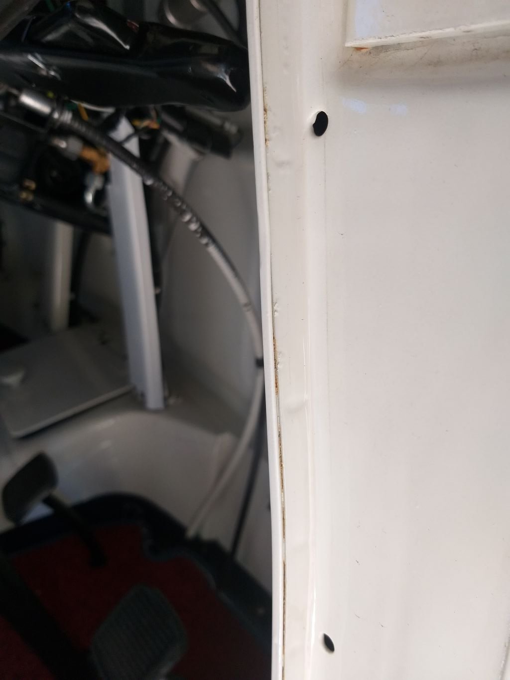
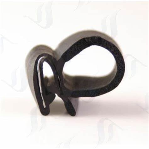
Today I tackled the next issue that was causing a drafty cabin. But first a bit of background: The factory original front door seals for a 400e look like so: And they are held in position with a bespoke metal clip that is pushed into a pressed hole in the body panel. Fixed in position without the rubber attached they look like so: And loose the clips look like so: When I bought the Thames, it came with a box of spares that included a brand-new set of repro door rubbers supplied by Sandy from the UK 400e Owner's Club. Unfortunately, the original mounting clips were missing and in chatting to Sandy he mentioned that the bespoke clips are now unobtainable with even second-hand units being as rare as the proverbial rocking horse poo. I put the word out that I was looking for some clips, but no luck. During our rainy season Mrs Flash and I were getting absolutely drenched every time we took the van out in the rain, so an urgent solution was required. Looking closely at the door surrounds I spotted a factory seam where the inner and outer body panels are joined. Looks like so: Looking at the little lip I wondered if it would be possible to source a universal side bubble pinch weld seal, so I asked Uncle Google for some help and he came up with this image: So on our next trip into town I visited Clark Rubber and they just so happened to have such a seal in stock. Grabbed enough to do one door and it worked like a charm. On the next town trip I grabbed another length for the other door and hey presto water be gone. Only problem was this bottom part where the front door extends below cabin floor level as there is no seam: So, at the time I just ignored that bit which was fine from a water ingress point of view, but now of course it's not so great for winter drafts and you would be amazed at how much cold air enters through that gap. Another plan was urgently needed so another visit to Clark Rubber and on the shelf, they had a little hollow half round section that had its own self-adhesive strip on the back. Again, I bought enough to do one door and fitted up it looks like so: At first the new rubber meant having to firmly close the door, but after a week it's settled down nicely and it's definitely sorted out the draft. Looks a bit untidy where the two seals meet, but I can live with that. We are off to town tomorrow, so I'll grab another length to finish off the passenger side door. Thanks for looking.
- 740 replies
-
- 13
-
-
Winter has set in with a vengeance here in Queensland ... well what we call winter. Daily highs are still in the mid 20s Celsius but some mornings we are down in the single digits which is cold for us softies. Driving the Thames around first thing in the morning I've discovered that it is quite drafty. So, this week I thought I'd make a start on sorting out some of the air leaks. First up the major draft: Some of you will recall that when I converted the van from column to floor shift, I hacked a ruddy great hole in the top of the air tunnel that looked like so: After fitting the shifter, I fabricated a little cover that looked like so: And everything in the garden was lovely until one day the panel bond that I used to glue the thing together let go and the top panel came off. At first I couldn't figure out why this had happened, but after looking a bit closer at things I realised we had a problem: As can be seen in the above photo when chucking the van into reverse the little ball joint on the cable was being lifted way high and it eventually popped the lid straight off like opening a tin of paint. How did I manage to cock that up I thought .... what a rookie mistake. Anyway, first thought was to move the whole cover higher up in the tunnel, but that was an instant fail as I was already right up against the engine cover hinge: Didn't really want to end up making a completely new cover that was tall enough to solve the problem, so ended up spacing the entire shift mechanism further away from the tunnel top by chucking in some longer mounting bolts with a few custom-made spacers. Dropping the entire mechanism led to some issues with the gearstick movement which meant I could no longer select reverse as the stick was hard up against the engine lid before reverse gear was fully engaged. Out came the gearstick and after tickling it with a blow torch I was able to tweak the angle of the gearstick in my vice. Took a few goes to get to the point where I could successfully select all gears. Chucked some fresh panel bond on the lid, clamped it back in place and let it go off overnight before refitting. And that was the major cause of the cold draft sorted.
- 740 replies
-
- 11
-
-
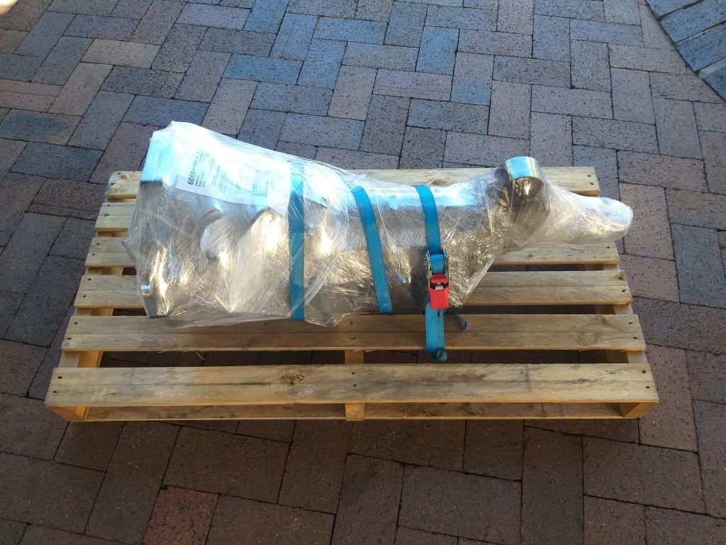
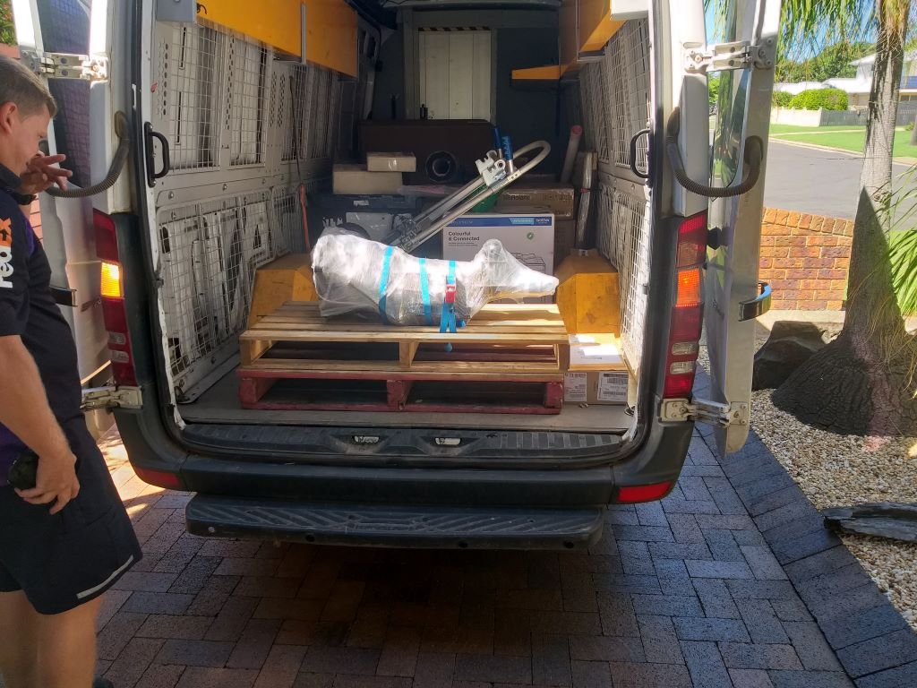
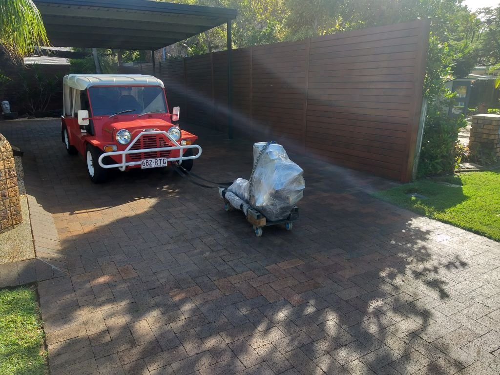
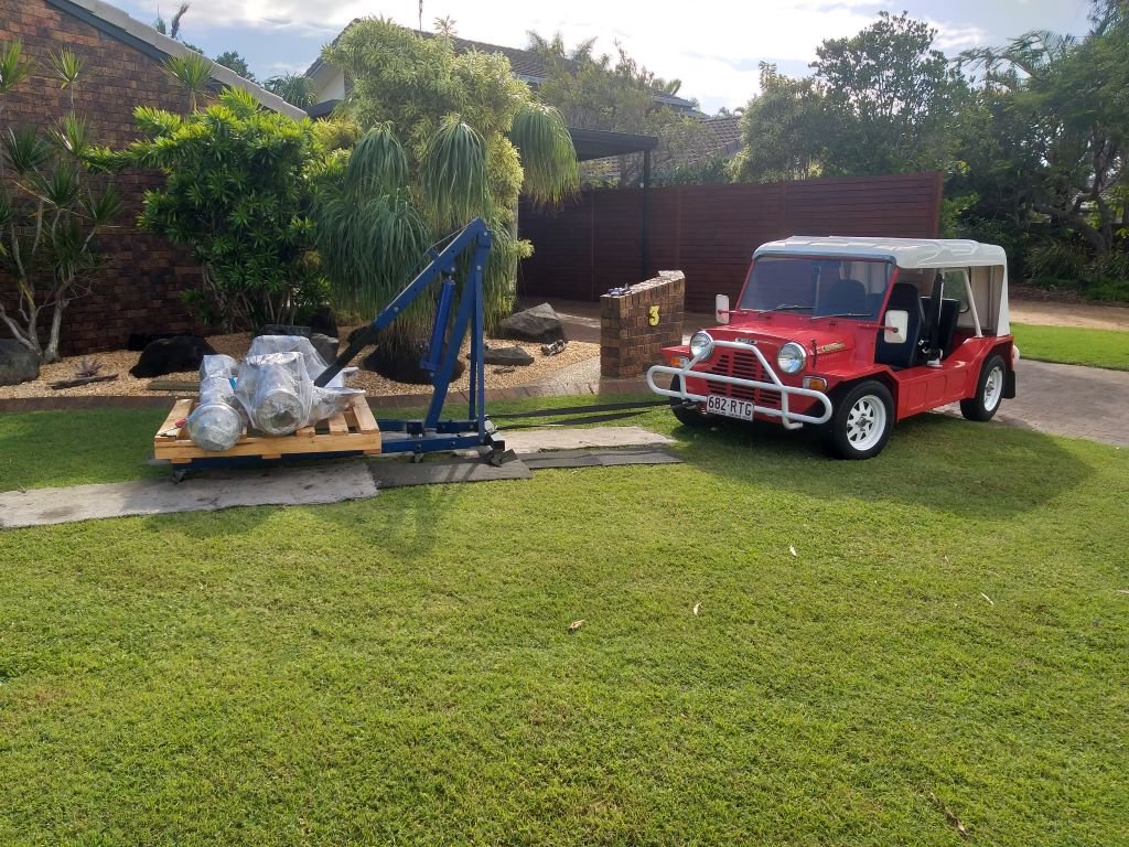
The plan was to keep the original Thames running gear in case anyone wanted to return it to factory sometime in the future. So, for the past few years it's all been languishing in my shed taking up valuable real estate and it's also been a real pain in the arse remembering to turn the engine over by hand every few months. Then earlier this year I realised that there is no way that I am ever going to return the Thames to factory and if ever I was to sell it the new owner is unlikely to do the same too. So I chucked an advert up on Gumtree and forgot about it. Had a few queries from Consul Barries as the Thames shares the same engine as a MK1 Consul, but apart from that all was quiet. And then about two weeks back I got a message from a chap based in Melbourne who is having a 1960 Thames 400e pickup restored and he was keen on my parts. A deal was struck and I spent a few days clearing enough crap out of the way to get to the parts with my engine crane. The stuff was bloody heavy and I'm not the biggest fella out there, so I had to get creative about moving the stuff around. Turned Mrs Flash's Moke into a little tractor and it worked like a charm. And that's everything cleaned, wrapped and strapped down to some old Bunnings pallets and ready to hit the road down Melbourne way.
- 740 replies
-
- 23
-
-
Okay, so the 4th June will mark one year since I got the Thames back on the road and we have clocked up just over 2,000 km of happy travels. Time sure flys when you are having fun. With nothing really exciting to report maintenance wise, I thought I'd give the Thames a birthday by cleaning up his little nest which was looking decidedly shabby. Crammed with leftover parts, the mock up 4Y engine and other crap accumulated during the build. I've been looking past this mess for way too long so time to do something about it. Before photo: I'm a hoarder of note so the first step was to find a new home for all of this crap. Opened up the roller door on my back shed for a look see and the answer was a definite no. Yikes, I really need to sort that shed out. It looks like something out of American Pickers except there aren't any treasures, just piles of junk that I can't bear to part with. So, with that option ruled out I figured another shed was needed. Like they say a man can never have too many sheds. We bought a little kit set and after boxing up a slab I got in a mini load of concrete and Mrs Flash and I did this: And then we waited for our poor old backs to recover before we did this: And then I spent a week moving all the gardening related items from the big shed into the little shed which freed up some space. After clearing all of the crap out of the Thames nest I then built a little wall unit to store everyday things like tools, washing buckets, trolley jacks, etc. I made the wall unit out of some old timber left over from our old kitchen and then disguised my shoddy carpentry with a good few coats of satin black. Gave the walls a lick of fresh paint and it ended up looking like this: Brought out my little collection of cartoon car sculptures and a few nautical themed bits and pieces that have been packed away for years, just to give the place a bit of bling. I had to buy a set of hinges for the tall cupboard doors and a pack of 400 wood screws, but apart from that everything else was leftovers. Mrs Flash has been spending a good bit of time in her art studio this year and created a whole heap of artwork for the garage, so after freshening up the paint we were able to create a feature wall. There are still a few gaps that Mrs Flash will fill over time, but all in all I'm really chuffed with the look. Next step is to epoxy coat the floor but I need to sort out a pesky rear main seal leak on the Mustang before we do that. Needless to say, the Thames van is very happy with his new nest. Thanks for looking.
- 740 replies
-
- 20
-
-
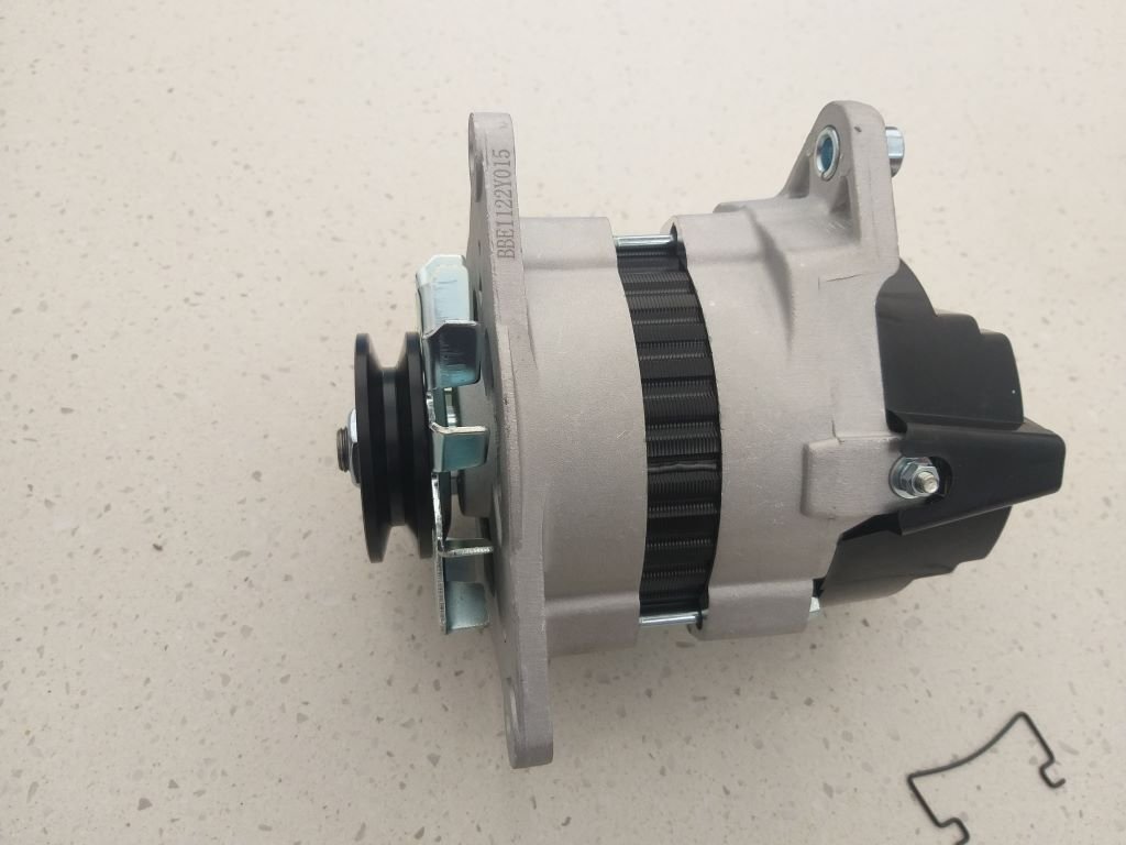
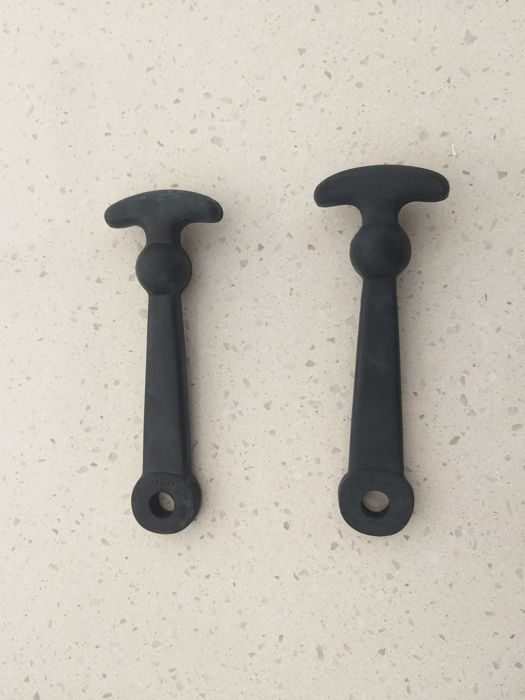
Earlier in the week whilst I was checking fluids, I noticed that the brake reservoir was pretty low. On closer inspection there were signs of a fluid leak around the reservoir itself. Yikes, that's not good. I then lifted the front rubber mat and discovered another patch of brake fluid on the floor. Figured it was time to rebuild the master cylinder, so ordered a kit from Minisport in Adelaide. I always try to order a few parts at a time just to get the most bang for buck out of the shipping cost, so I also ordered a new set of bonnet straps as the existing ones were looking a bit dodgy. At $30 per bonnet strap the new ones were pretty spendy, but they are Australian made so I figured they would hold up in the local sun a lot better than their Pommy cousins. Last item included in the parcel was a new alternator to replace the ailing Lucas 16ACR unit which hasn't been charging properly for a few months. The alternator light would remain on for anything below about 2000 RPM, so I knew it was on its way. Parts arrived promptly and I cracked straight into the master cylinder rebuild. As you can see from the photo below the paint overspray on the parts are definite signs that the master cylinder was left in situ during the body restoration. Another sign of neglect was the perished dust boot. Stripped it down and gave it a good clean before closer inspection. Seals were hard and nasty looking. Bore was still perfect, but I gave the cylinder a light tickle with a bit of 1200 grit sandpaper anyway before lubing up the new seals and chucking them in. Replaced the seal on the reservoir at the same time. The master bled up easily which was a win. Next task was the alternator replacement. Again pretty straight forward. Minisport were out of stock on the drive belt, so I had to source a new one locally. Finished off by fitting the new bonnet straps and all is good in Moke world once more. Thanks for looking.
- 9 replies
-
- 16
-
-
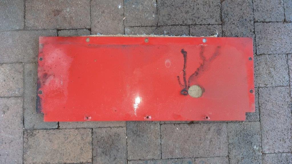
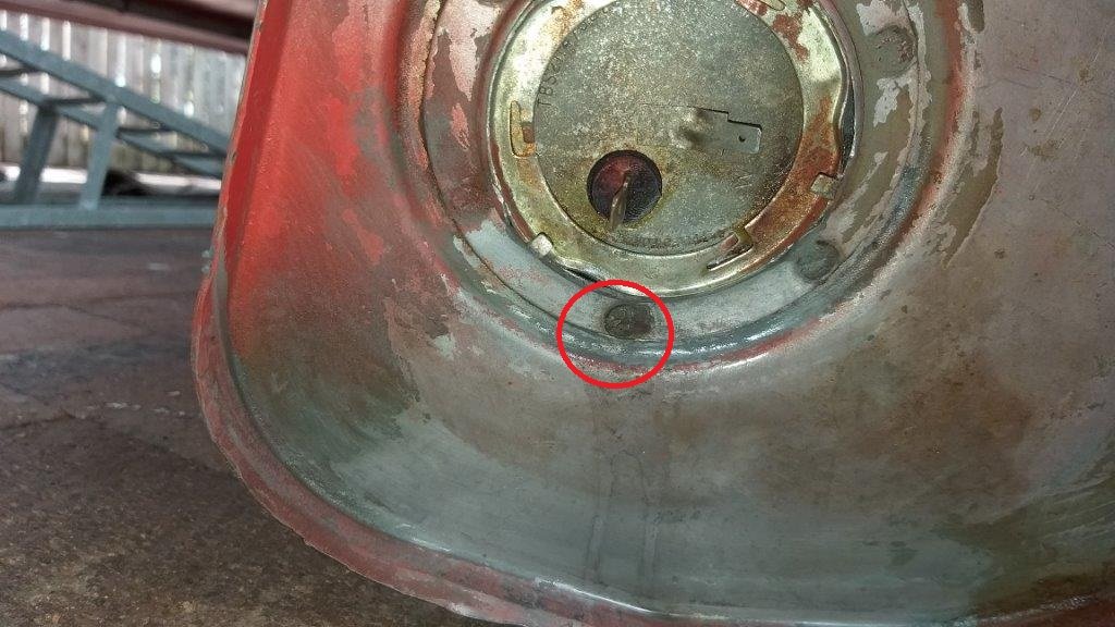
Since day one of ownership the Moke has always whiffed of fuel when parked in our garage. At first I attributed the issue to the cork gasket on the fuel cap which was badly shagged. I ordered a new one from Minisport but it made no difference. I began to notice that the smell was particularly bad when the tank was anyithing above about half full. We lived with the problem for a good while until one day I decided it was time to do something about it. Crawled underneath and removed the under tank cover plate for a quick look see. Sure enough there were signs of old fuel drips on the inside of the cover plate. At this stage I suspected the problem to be the sender unit rubber seal that sits on the side of the tank. So out came the tank and I removed the sender unit and replaced the seal. Sadly still no luck. In desperation I decided to drop the tank one more time, then filled it up with fuel to just past the sender unit to see what would happen. And .... a slow leak from one of the spot welds that hold the tank sender locating collar in place. I ended up chucking some JB Weld over the spot and that solved the issue.
- 9 replies
-
- 15
-
-
However, during the pre purchase inspection I picked up a few things in the engine bay and suspension wise that placed some doubt on how far the mechanical restoration had been taken. Nothing major, but just little signs that some items still needed attention. On getting it home, the first thing that I did was to fit an electronic unit to the existing distributor in the hopes of resolving an intermittent misfire. We then clocked up about 1000km during which time I was almost constantly fiddling about to try and get the timing right. In desperation I eventually pulled the dizzy out for a closer look and discovered excessive play in the shaft, so I ended up ordering a brand-new distributor from MiniSport in Adelaide. The new distributor came with its own set of electronic internals already fitted so the old unit went into the parts bin. This solved the misfire, and we ended up enjoying another 500km of trouble-free motoring until one day the Moke just suddenly cut out and left us stranded at the side of the road. Luckily, we were close to home, so I walked the rest of the way and returned with our Holden ute and a tow rope. After a bit of troubleshooting, I pinpointed a fuelling issue which turned out to be a faulty float valve. Got a new one sent up from MiniSport and we were back in business. Shortly after that the actual carby started playing up - again excessive wear - and we ended up ordering a reconditioned SU from MiniSport. Since then its literally been an annual oil and filter change and the fitting of a new battery and we are now up to around 2400km of travel that we have undertaken since purchase. And that pretty much brings us up to this point in time. In my next update I'll cover some additional maintenance work that has happened over the past few weeks. And no one likes a pictureless update so here is a group photo of our small fleet:
- 9 replies
-
- 32
-
-
When we purchased the little Moke it had only travelled 1614km since being restored born witness by the odometer reading on the brand new Speedo. The story goes that a father restored the Moke for his disabled son. The son was wheelchair bound and old mate had even fitted 12 volt rams to the rear hinged fibreglass roof so that he could get the youngster in and out of the passenger seat. Problem was that the youngster didn't have much upper body control either and nearly fell out of the Moke on the first outing. The family got such a scare that the Moke got parked up for a while before they sold it on to a young fella from Noosa. I think that the new owner fell in love with the idea of owning an old classic without realising that it isn't like driving a modern hatchback with all the mod cons. He was also not mechanically minded so he ended up farming the maintenance out to a local mechanic and after receiving a few repair bills the novelty of owning the Moke wore off. And its at this point that Mrs Flash and I stepped in to take over the reins. So, both inwardly and outwardly the Moke looked absolutely immaculate as borne out by the below photos that I saved from the original advertisment:
- 9 replies
-
- 20
-
-
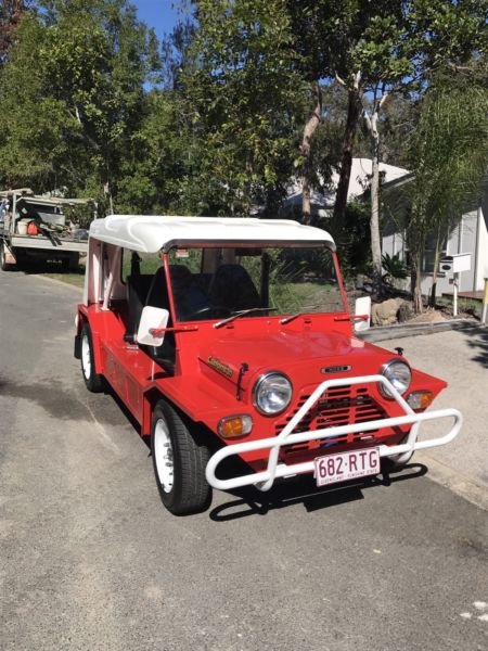
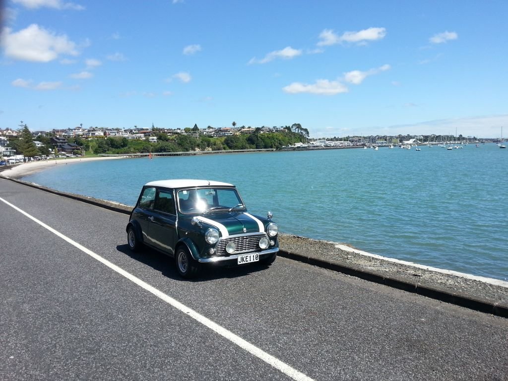
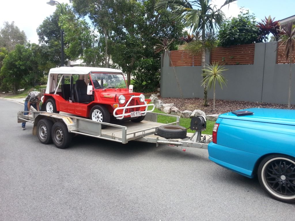
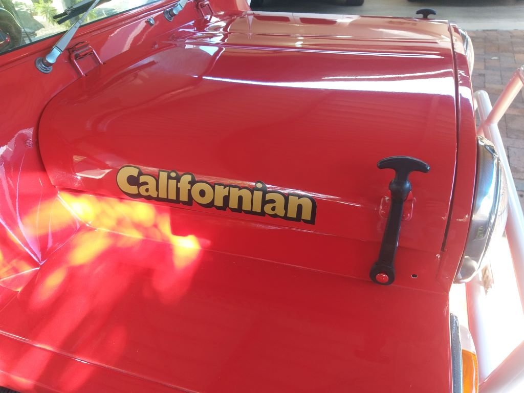
We have owned this little Moke for about 4 years now and since I'm starting to do a bit of work on it, I figured I'd start a thread as it might be of interest to others. So, first up a bit of background. When we lived in NZ, Mrs Flash owned one of those newish 1275cc SPI Rover Minis. It was a Jap import that someone had done quite a bit of back dating on. A lot of the changes were fairly subtle, but the most notable things were the fitting of 10-inch Watanabe rims to replace the original 13-inch units and the removal of the modern dashboard that was replaced with a classic centre mount speedo. The car was a little rocket and super fun to drive. Sadly, we made the decision to sell it before heading off on our Australian adventure and last I heard it was somewhere in Christchurch. So fast forward a few years and we are now permanently OZ based and looking to get back into some classics. We often thought back to the fun that we had with that little Mini and decided that owning another little Leyland would be good. The climate over in tropical Queensland lends itself to something a little more open and so we set our sights on a Moke. After checking out a few we ended up pulling the trigger on a fully restored 1100cc powered 1974 Californian look alike that was going for reasonable money. When I say reasonable I really mean that after doing my own sums I concluded that I couldn't have restored a clunker to this level for the money that was being asked. So, after swapping a few calls with the current owner together with the studying of some detailed photos a "deal in principle" was struck pending final inspection. We grabbed a hire trailer and headed south down to Noosa hoping to be returning with a loaded trailer. Gave it the once over, took it for a quick drive, some cash changed hands, and this happened: In my next update I'll talk about the maintenance undertaken to date and then a little bit about the current work being done. Thanks for looking.
- 9 replies
-
- 27
-

-
-
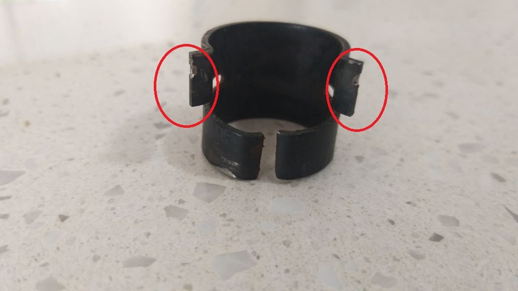
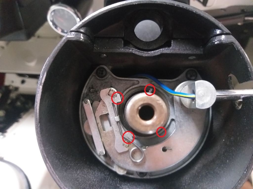
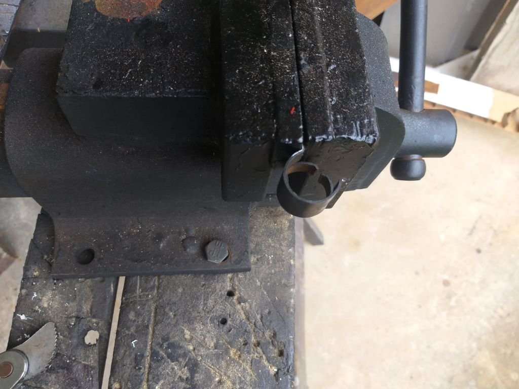
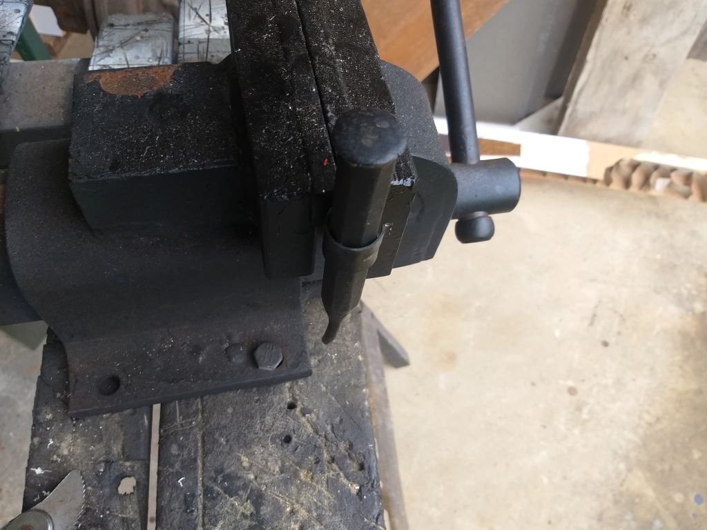
Over the last few weeks, I've noticed a steadily increasing stiffer steering and during last night's burger cruise it felt particularly bad. Figured I'd do a bit of fault finding today. First step was to remove the intermediate steering shaft to determine whether the issue was on the steering rack end or the column end. With the intermediate shaft out I fired up the engine and waited the few seconds for the Astra pump to come online. What a relief it was to find out that the issue is not on the rack/pump side of things. So turned my attention to the angled steering gearbox and the steering shaft itself. Pulled out the angled gearbox for a closer look. Popped the cover off to check the lubricant level. Turns out it uses grease - or at least mine is filled with grease. I'm hoping that is factory and not some previous owner's bodge job. Anyone know ? Anyway, I neglected to take a photo, but it looked like some of the grease had shifted leaving the top half of one of the gears dry. The grease looked to be clean and still in good condition, so I just topped up the level and fitted the cover plate back on. At the same time I spent a bit of time fine tuning the little adjusting thingy till I got the mechanism turning smoothly: While I had the angle box out, I pulled off the steering wheel and dropped the shaft so that I could grease the upper and lower bushes. They were pretty dry. With the steering wheel off I figured I'd tackle another annoying little issue. For a good while the indicator self cancelling feature on left turns hasn't been working. Works perfect on right turns though. Really aggravating as I keep forgetting to manually cancel the flashers and also pretty unsafe. Anyhoo, I took a closer look at the mechanism and it was visibly okay. There are two little "ears" on a spring steel collar that press fits over the inner steering shaft. Looks like so: Each little "ear" engages with a double ended lever attached to the indicator mechanism. One of the "ears" isn't visible due to the angle of my photo, but I've marked up where it is supposed to be. With a visible inspection not showing anything untoward I enlisted Mr's Flash's help to watch what was going on while I turned the steering shaft from below. Turns out the little "ear" on left turns was not triggering the self-cancelling lever. Pulled it out the collar for a closer look. Both "ears" are showing signs of wear with noticeably more wear on the left one. Thought I'd try and give it a tweak, so clamped the offending "ear" in my vice: Chucked an appropriately sized punch down the centre of the collar to maintain its shape: Then gave it a little bit of loving with a hammer. Popped it back on the column for another test and ... success! With the self-cancelling issue sorted I reassembled the steering and dropped the van back on its front wheels for a quick steering test. Nice and light once again. Loaded up my ratchet with the appropriately sized socket and headed out for a road test and also to re-centralise the steering wheel. It took a few goes until I got the steering wheel perfect, but I'm happy that things are now back to normal. Thanks for looking.
- 740 replies
-
- 15
-
-
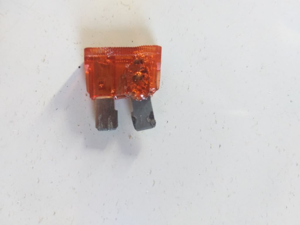
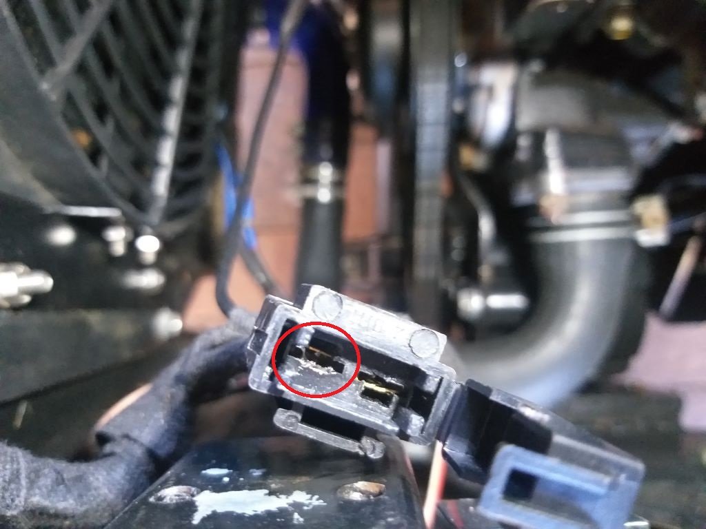
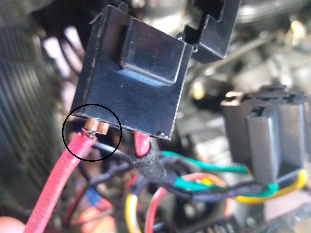
Last week we headed off on a supply run in the pouring rain and as we got into town, I noticed the temp creeping up above normal. Quickly pulled over and switched off and when I cycled the ignition key to the aux setting I noticed no noise coming from the thermo fan. WTF. Checked the under dash fuse panel and the fuse for the thermo fan relay exciter wire was still good. Lifted the engine cover lid to get a closer look at the inline fuse on the relay power feed. Bloody fuse wouldn't come out. Grabbed a pair of longnose pliers from my tool kit and gave the fuse a bloody good yank and out she came. Yikes, definite signs of overheating, but the fuse itself was still intact. Fuse holder looked decidedly shabby too. Looking at the back of the fuse holder and I could immediately tell that the input wire on the connector had dropped. Managed to push the connector back into the housing and with a working fan we were back on the road again. Fast forward to today and I figured I'd best do a proper fix. Luckily, I had one of those fairly robust auto reset trip switches in stock, so I've mounted that in the battery box and have run a new relay power feed directly from the battery. The relay trigger wire is still ignition switch activated via a separate fuse from the under dash fuse panel. Longer term I need to replace the crappy thermo fan with a decent Spal unit as the cheapies sure do suck up the amps.
- 740 replies
-
- 12
-
-
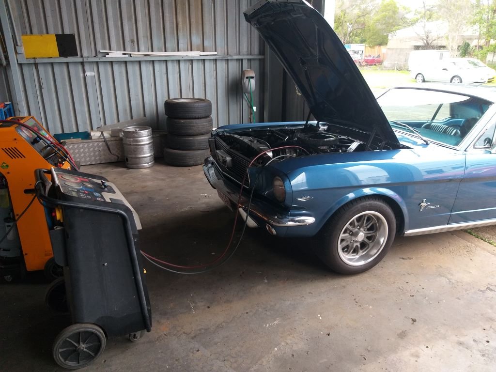
It's been a few months since my last update. The Thames is still going strong although I've got a few niggly bits to sort out. My a/c unit is on a 30-amp fuse which occasionally blows on startup so I'm thinking of fitting a auto-reset circuit breaker instead. Also looks like my decision to fit the second-hand a/c compressor has come back to bite me on the arse. The a/c works well but there is excessive drag on the drive belt resulting in lots of rubber dust and I have to keep adjusting the belt as it starts screeching after about 100km of travel. Dropped by my a/c guy a few weeks back and after checking it out he confirmed that the compressor needs replacing. In order to free up some cash for the new compressor I chucked my auto trannies on Marketplace and one of them sold to a Gearbox Repair Centre in Western Australia. Hopefully the next one goes soon.
-
@Gee, in terms of the EFI setup I've just been experimenting on my own. Got to admit that I'm a total newbie when it comes to EFI. I'm not chasing performance at all, mainly focused on economy and driveability. The car runs really well apart from the fumes at idle issue and I'm now suspecting that I may have a dicky Idle Air Controller as I've set it up a number of times according to Fitech's "how to" video clip, but for some reason the IAC count at idle seems to climb after a bit of driving. Fitech use a "no name brand" copy of a genuine AC Delco part out of a mid 80s Camaro. I tried to order one in from Rockauto but the Delco one is NLA. They do list some other brands for the same part so I might just order one in when I've got some spare cash. At least then I can rule that out as the issue.
-
Yep I reckon you are bang on the money Clint. The normal tyre places used the standard Mustang settings, but the suspension guys did their own thing and it made a massive difference. Next time I'm in town I'll drop by the shop as I'm sure they will have a record of the settings they used. This might help @Gee out with his setup.
-
Yep, that's pretty much how mine feels too, so maybe that's how they all are with the ram type p/s. How new is your front rubber and I'm assuming you have had a pro do your wheel alignment? I took my car to 3 different wheel alignment guys before I got it right. The first two were just your usual tyre places, but the 3rd guy was a suspension specialist and whatever he did it made a huge difference to the road feel. Before that it would wander about a bit on a straight road and feel a bit iffy in corners, but now it feels better in corners and runs true if I let the wheel go when I'm travelling in a straight line. Unfortunately, the 3rd guy didn't give me a printout so I can't compare the settings that he did with the others, but I was hanging around while he did it and it looked to me like he spent a good bit of effort on the caster settings. I'm still struggling with fumes but it only occurs at idle when I've pulled to a stop at a traffic light or stop sign and only when I have the front windows open. Having EFI I'm able to just about infinitely tune the bloody thing and I've been playing around with the idle fuel settings at various temperatures as well as my AFR targets, but I still can't shake the smell.
-
Yep, my steering is good now although I do get that slight play in the wheel when the power valve is at rest (ie travelling in a straight line). When you say it "clunks" are you hearing an actual noise or is it just the play ?
-
First thing this morning Josh gassed up the a/c which is now back in perfect working order. Hopefully that's the Mustang sorted for the next few months.
- 198 replies
-
- 14
-
-
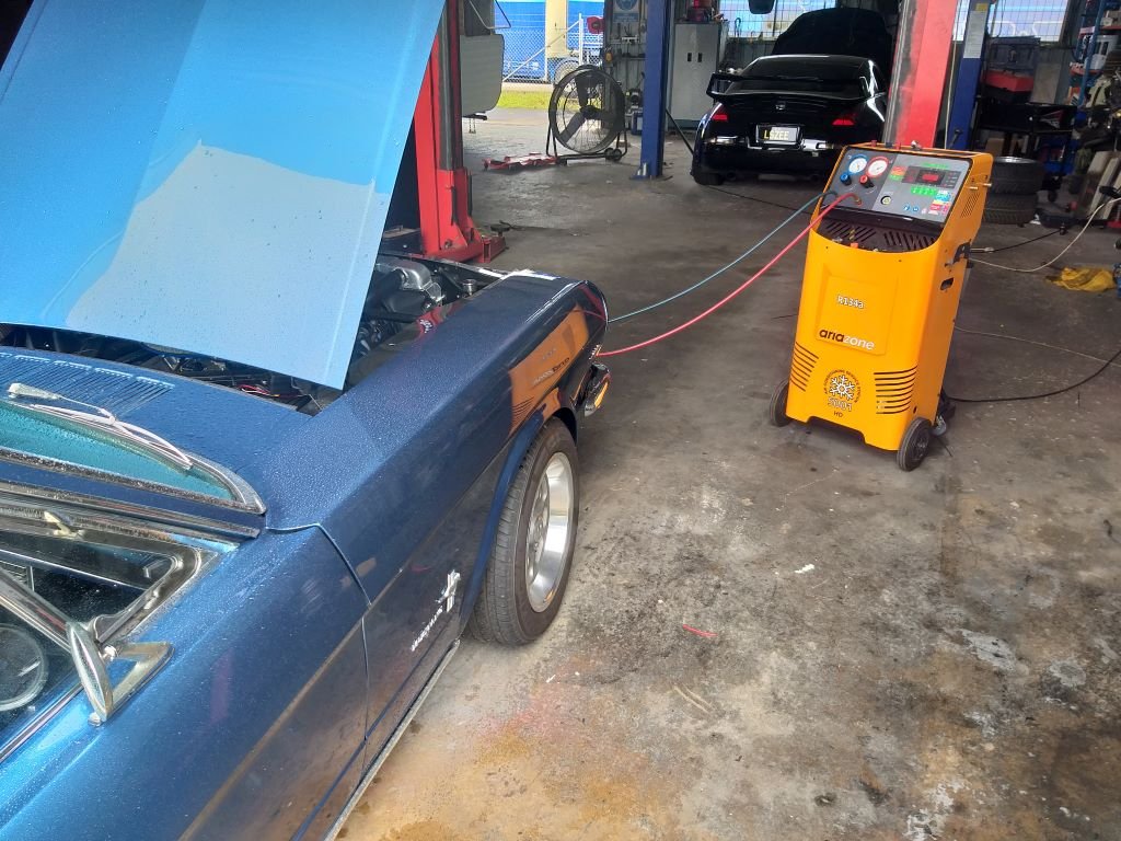
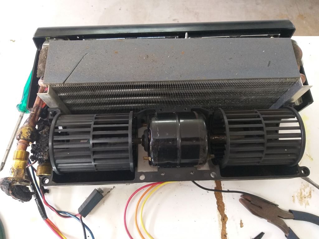
Recently the a/c blower fan has been making an intermittent grinding sound which has been getting steadily worse. I figured it was a sign that the motor was on its last legs. So, on my way back from the alignment shop I wheeled past the a/c place and Josh quickly dropped the gas for me. Oh, by the way, that black beastie in the background is an LS3 powered 350Z that is in for some a/c work. Anyway, back home I pulled the under-dash unit out and opened it up: Chucked a battery on it and fired up the motor. Sure enough grinding sound started up almost straight away. Turns out the hamster wheel on the left was just touching the inner rim of the casing. Yikes can it be that simple I thought. Removed the small holding clamp and slid the wheel slightly outward till it cleared the casing a bit more before reinstalling the holding clamp. Tested it again and it was running smooth as silk. Unit is back together and reinstalled with fresh o rings on the a/c lines and a brand-new receiver/drier. It's booked in for a re-gas first thing on Friday morning.
- 198 replies
-
- 11
-
-
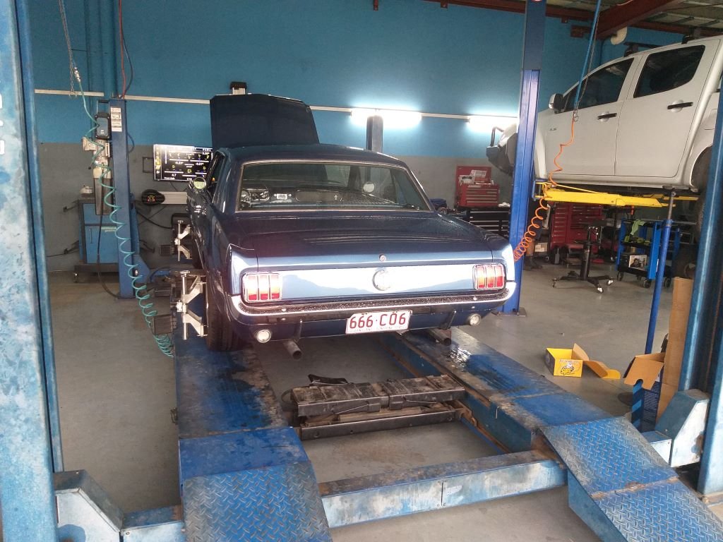
First thing this morning I headed into town for a hot date with the wheel alignment boys. AAA+++. Would trade again.
-
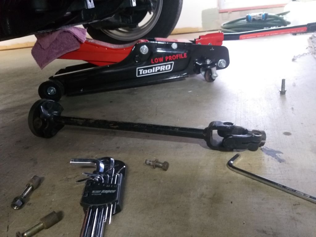
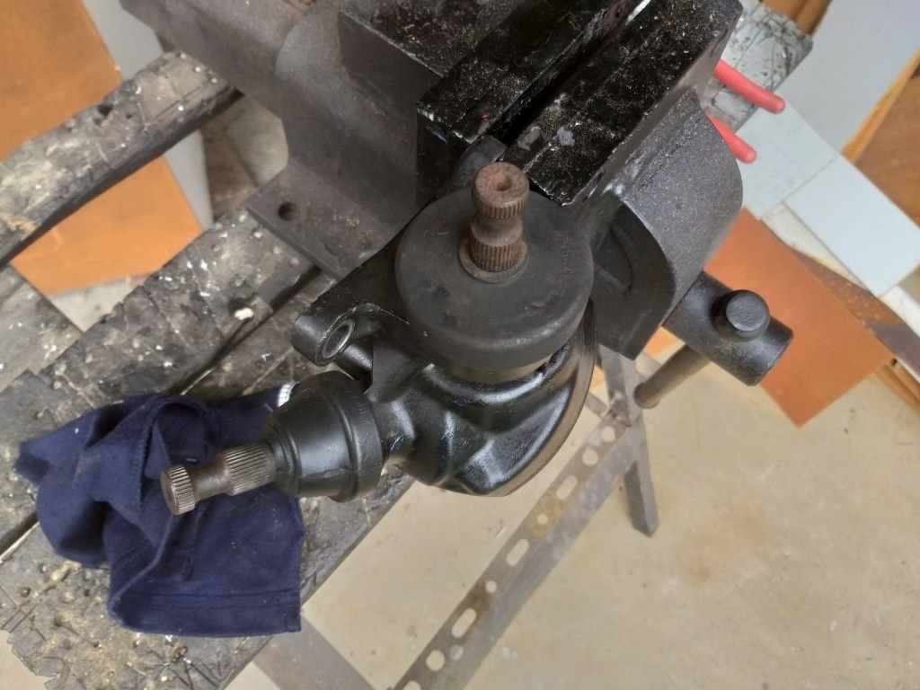
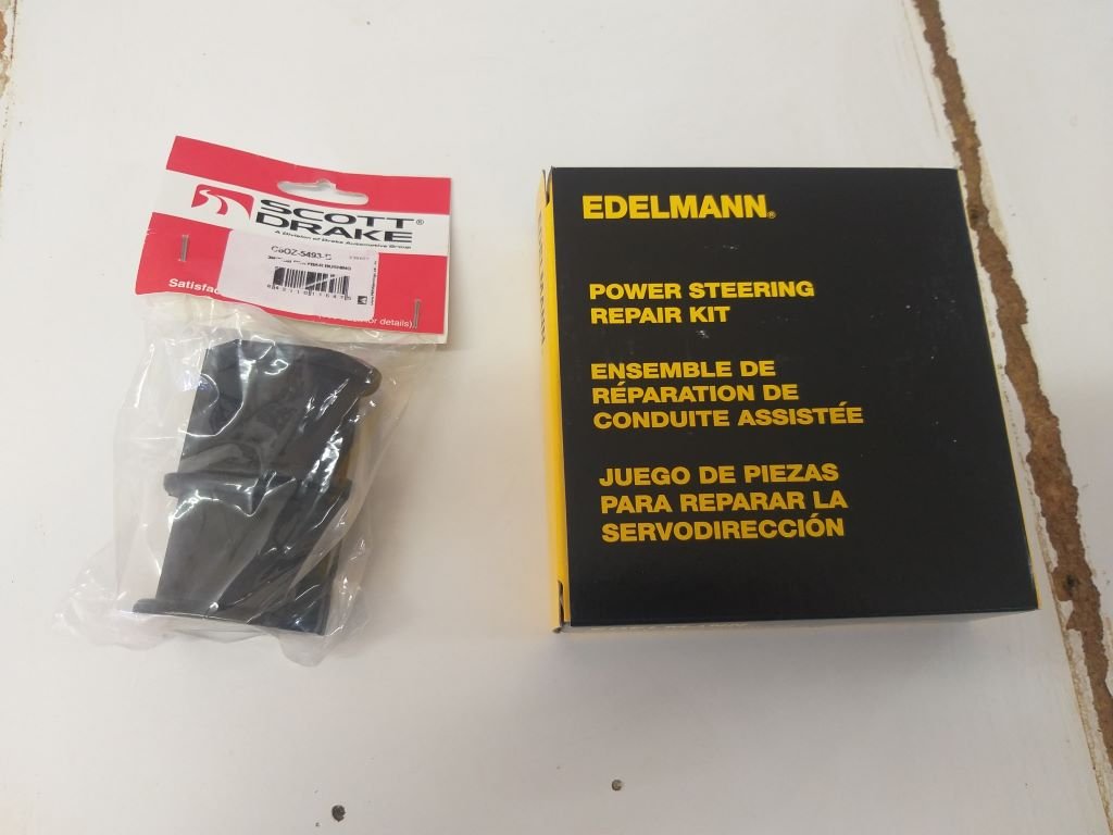
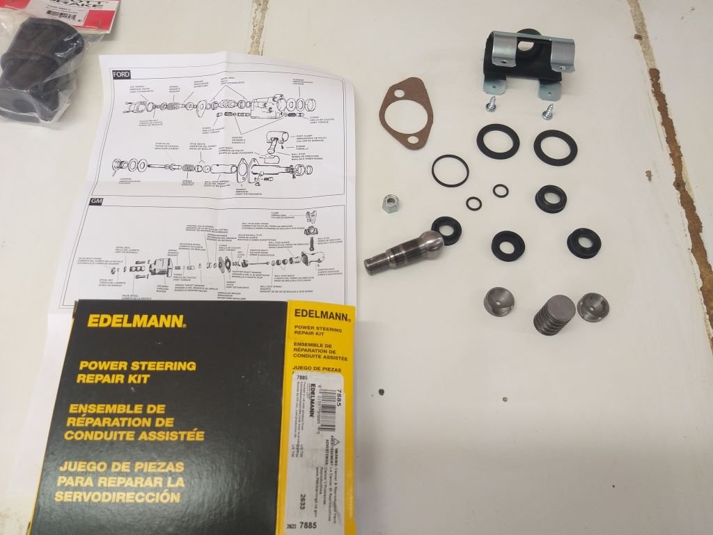
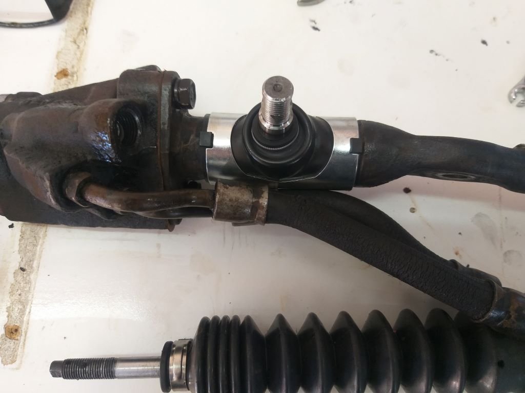
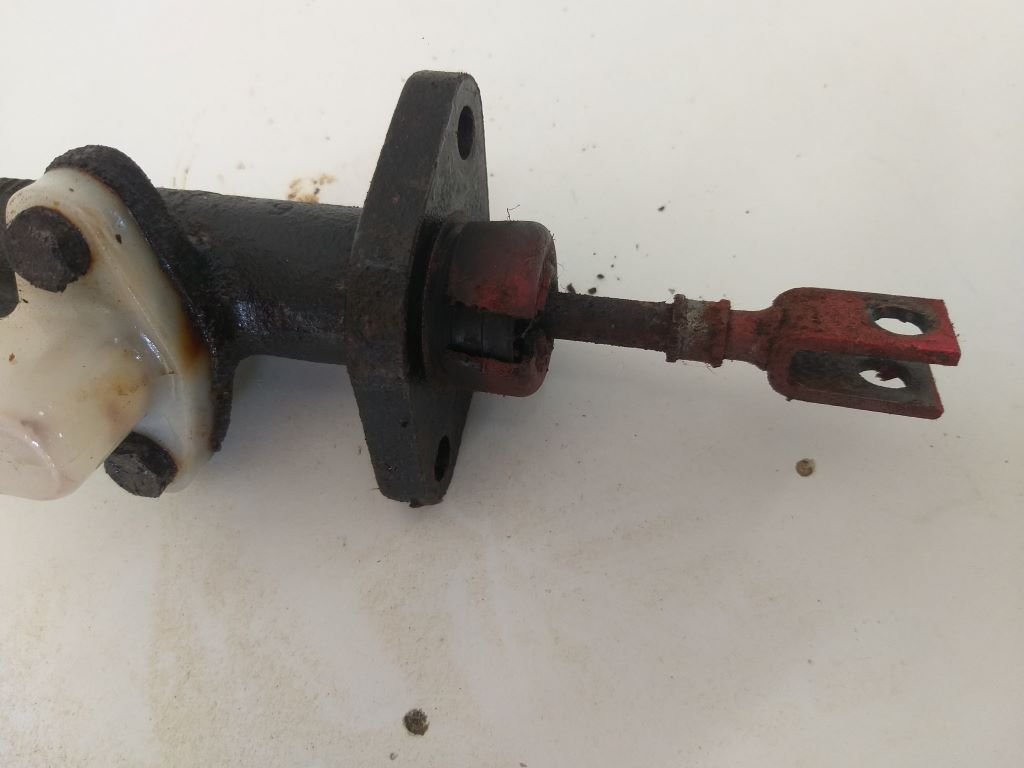
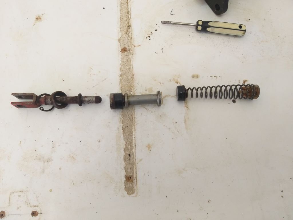
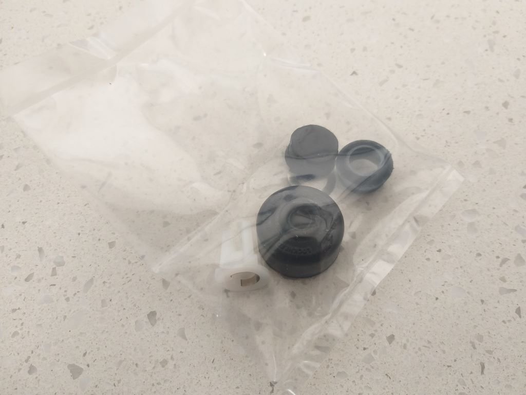
The rebuild kit for the power steering ram and a new set of sway bar bushes pitched up yesterday arvo. So, this morning I cracked straight into it. Nek minnit: Yummy.
- 198 replies
-
- 10
-
-
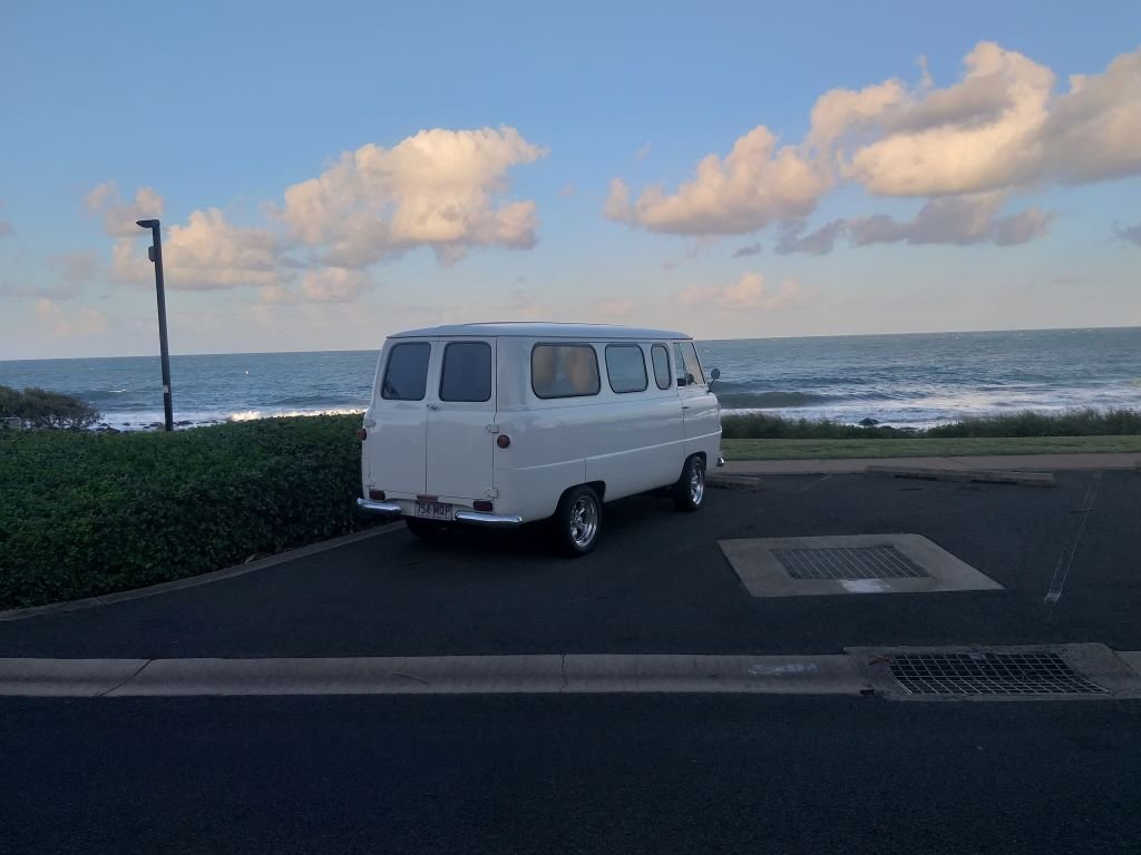
Our usual Friday night cruise followed by burgers at the beach.
- 740 replies
-
- 17
-
-
Yep, lock to lock and the closest I get to the header is 40mm. Guess I just got lucky.
-
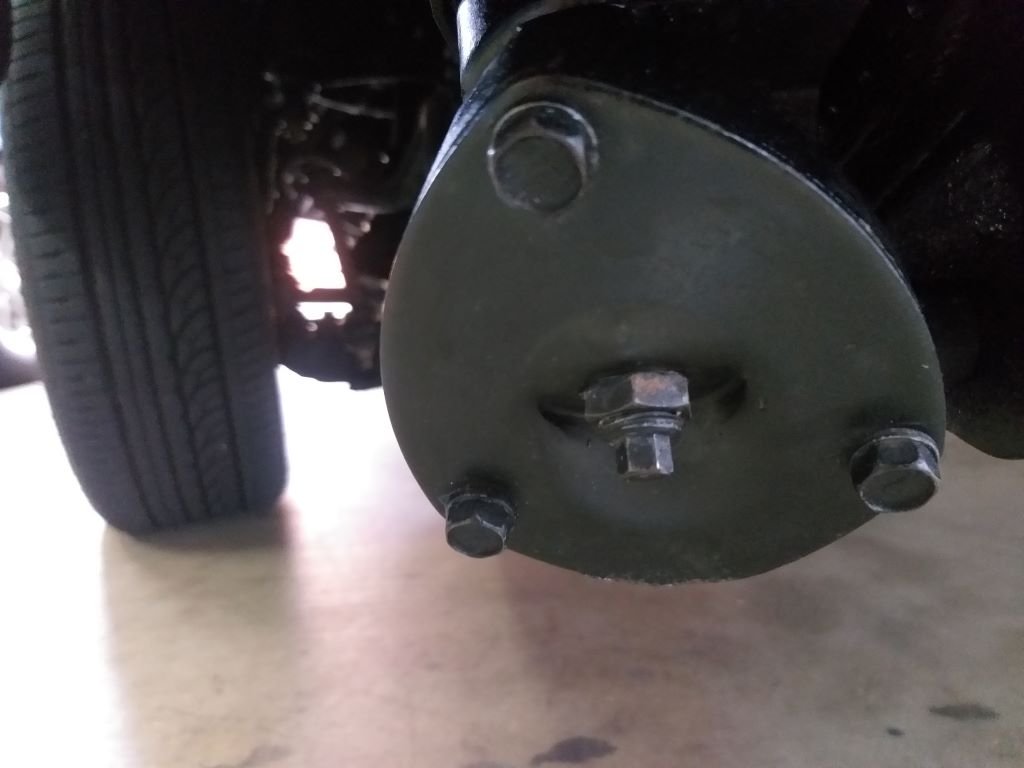
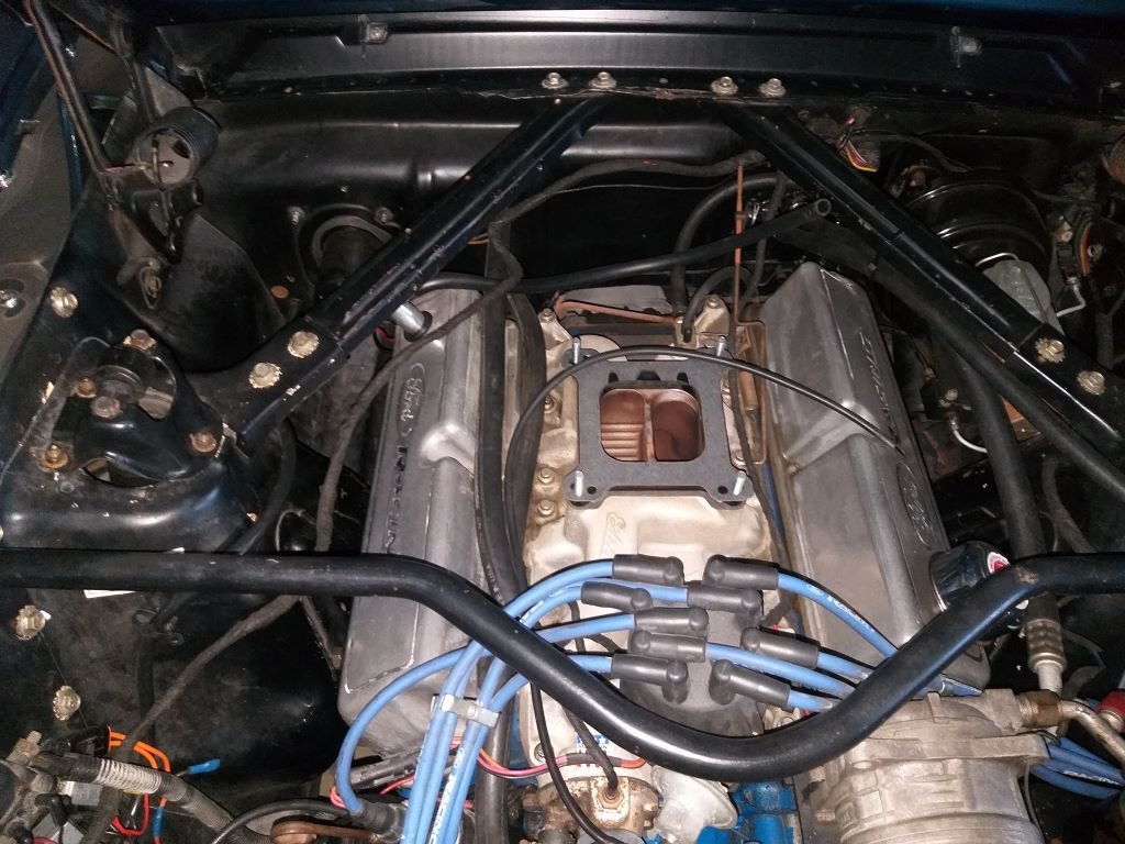
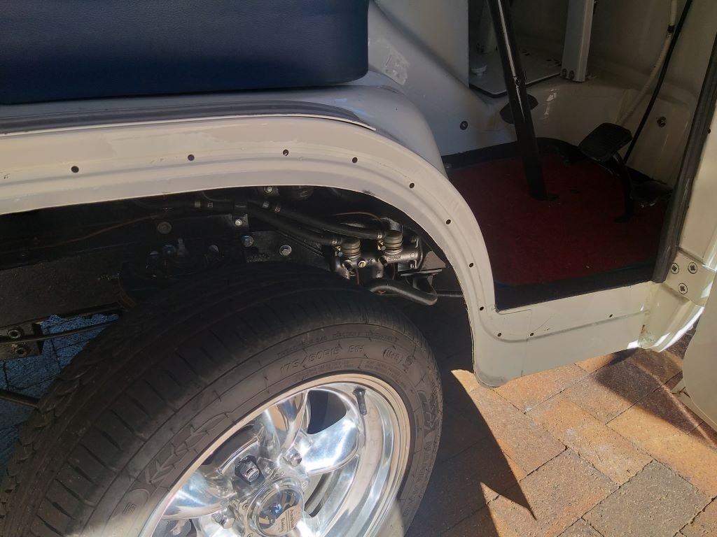
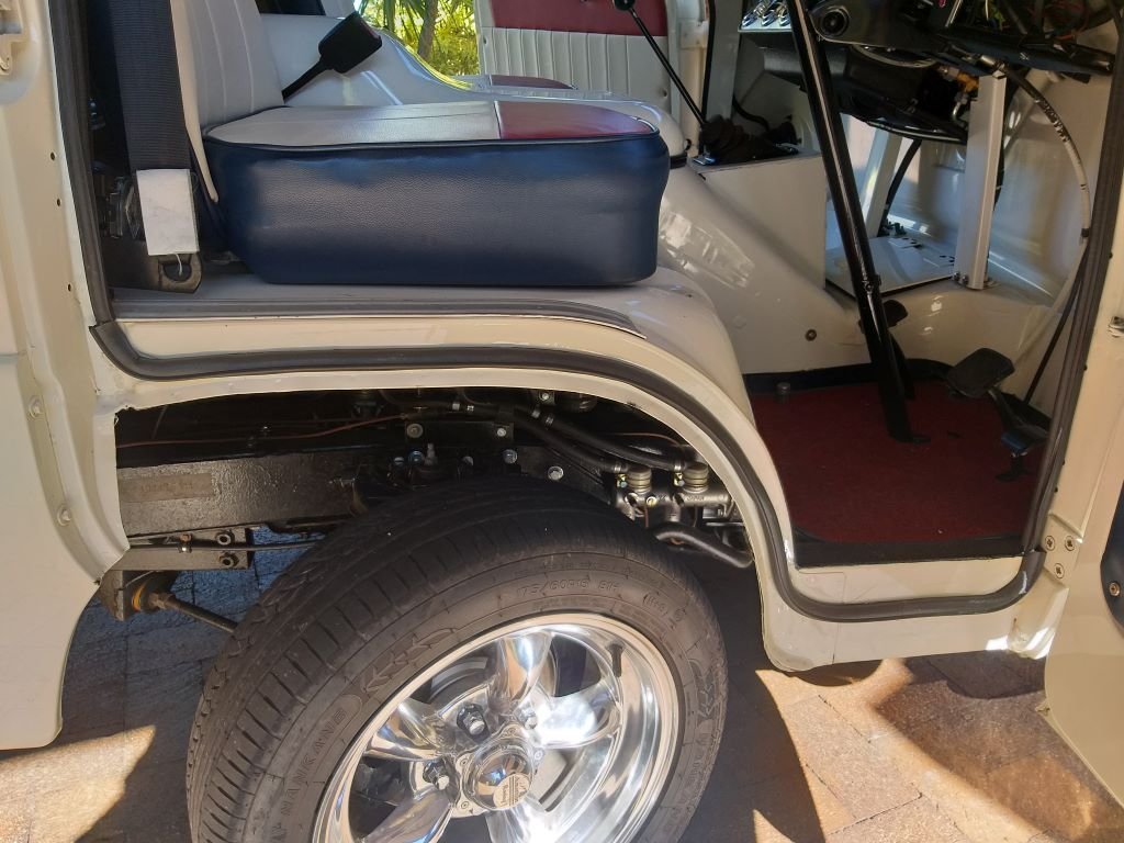
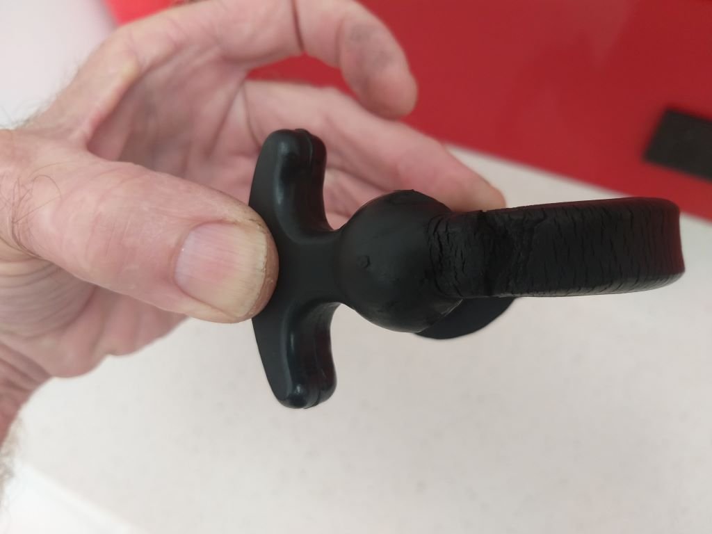
Thanks for the info on your alternator. I've just finished rebuilding the power valve with the kit that arrived yesterday. Not too bad a job once I'd watched the CJ Pony Parts "how to" Youtube clip a good few times. Just measured and I've got 40mm clearance between my header and the power steering pipes which sounds okay. Things can be a bit hit or miss with the aftermarket headers. My RHS one is an absolute shocker in terms of clearance. For added protection I might just wrap that LHS header so it matches the RHS one and it will also give the power steer hoses a bit of heat relief too.


.JPG.911996a57340489b89409222facd1532.JPG)
.JPG.32ca8111e8a98af724dd0f2e2c95b891.JPG)
.JPG.893e17939e59eecb0ff27421c7b47d00.JPG)
.JPG.4314fad55b635779c2c647b6d56b1709.JPG)
.JPG.5224b5e07dac0595316b8abde0085eb5.JPG)
.JPG.d527fed8e5a257d86f52d15d2c74e985.JPG)