Flash
-
Posts
1,719 -
Joined
-
Last visited
-
Days Won
2
Content Type
Forums
Downloads
Events
Gallery
Everything posted by Flash
-
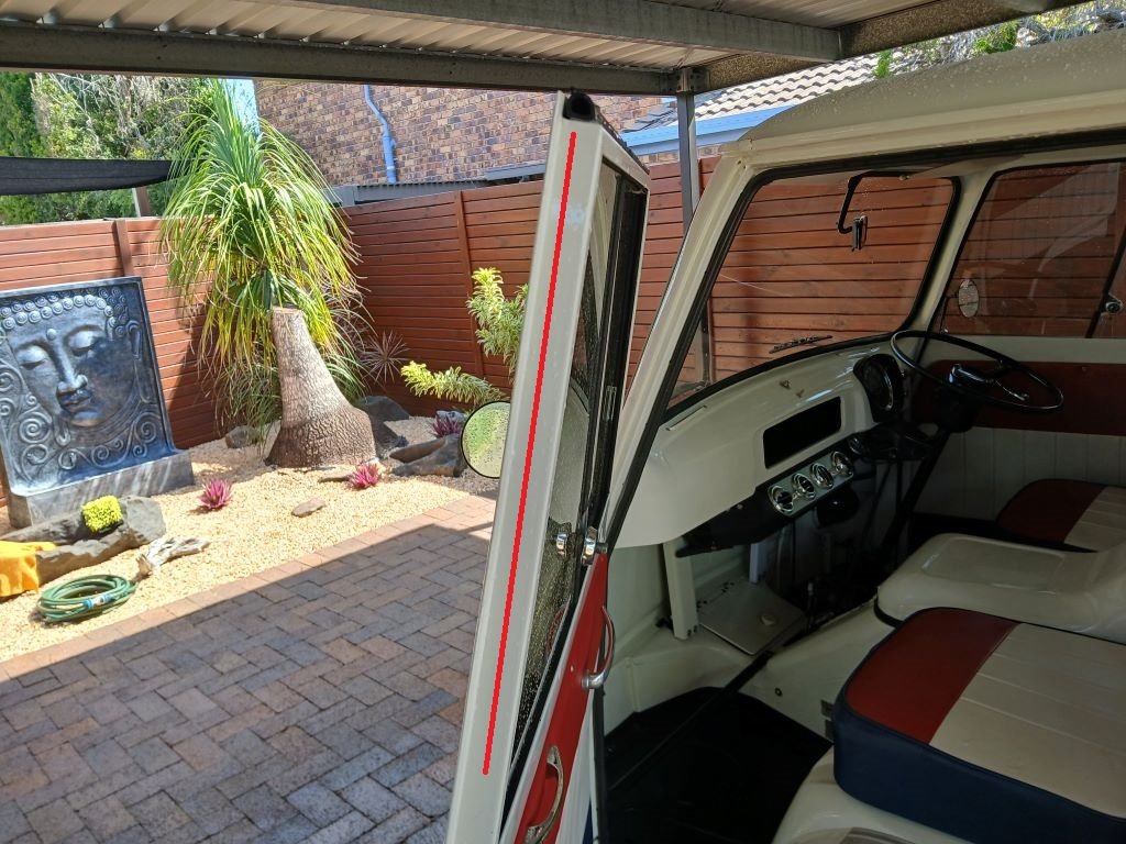
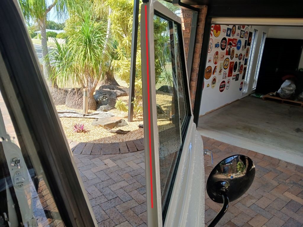
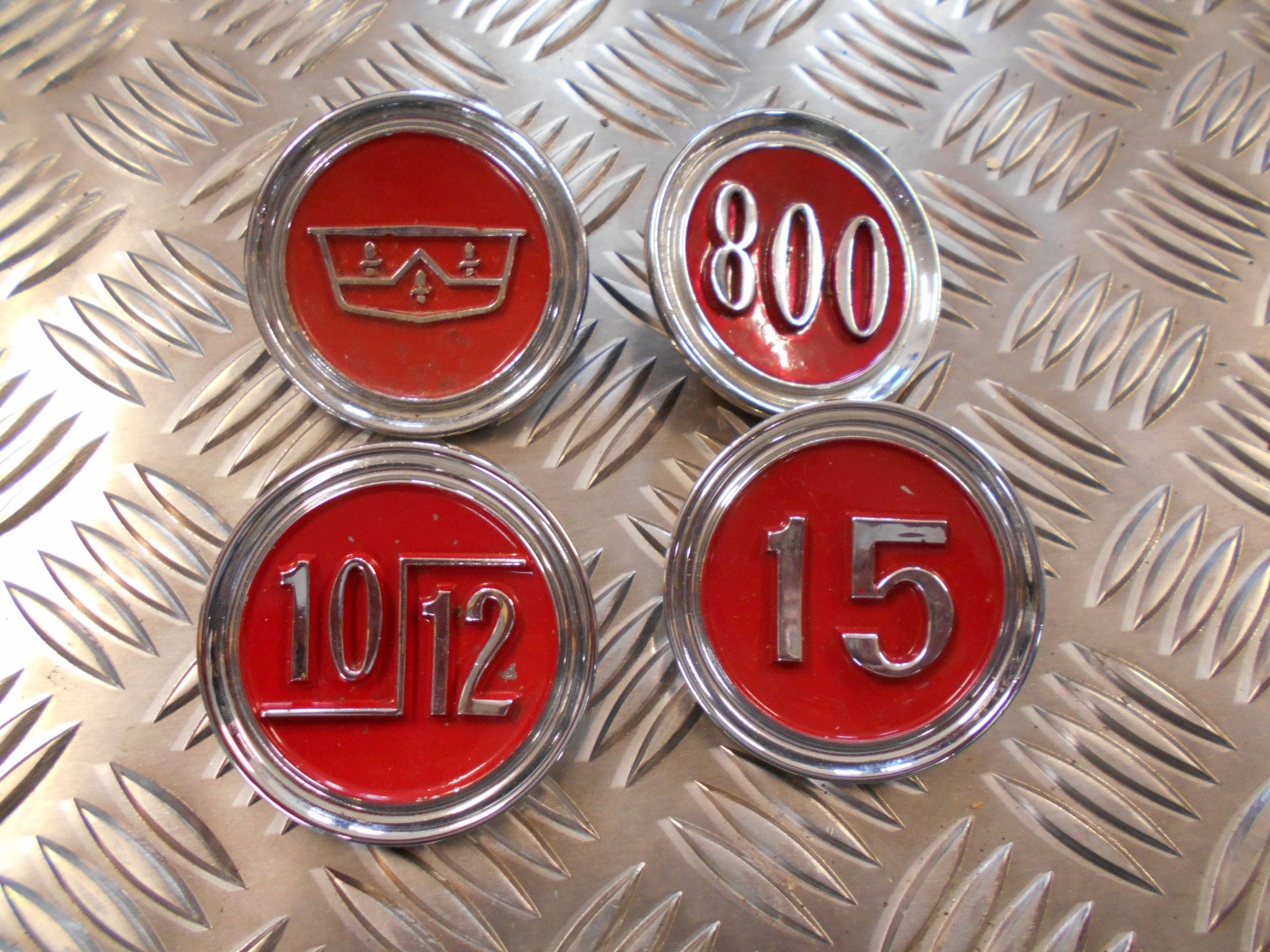
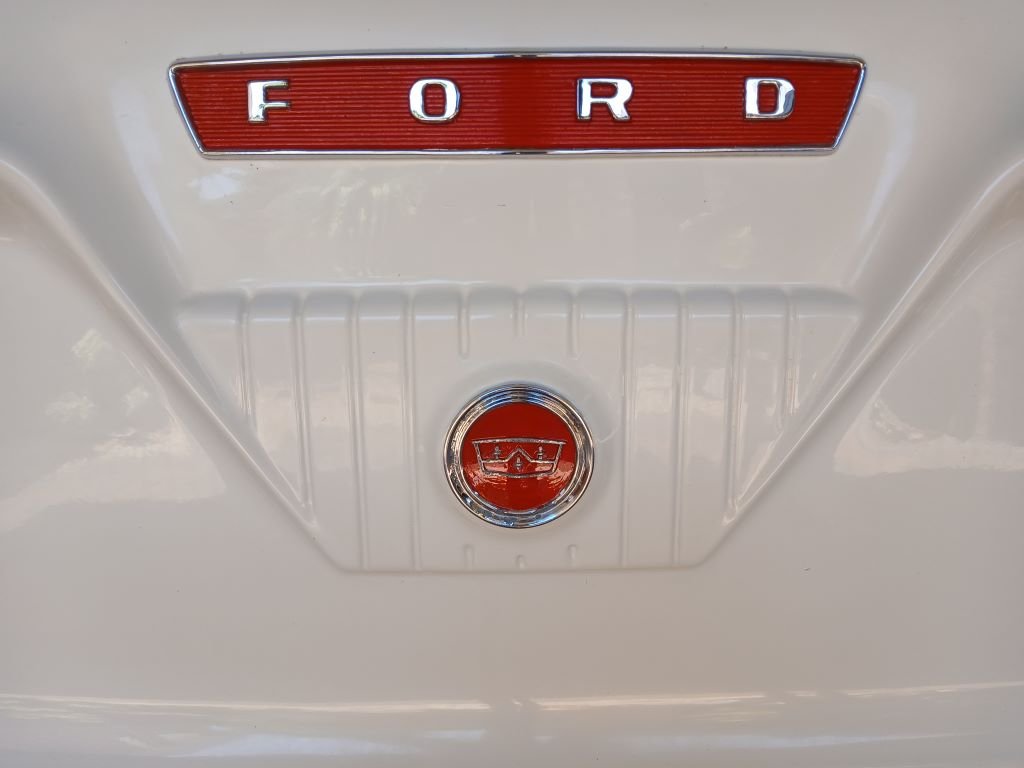
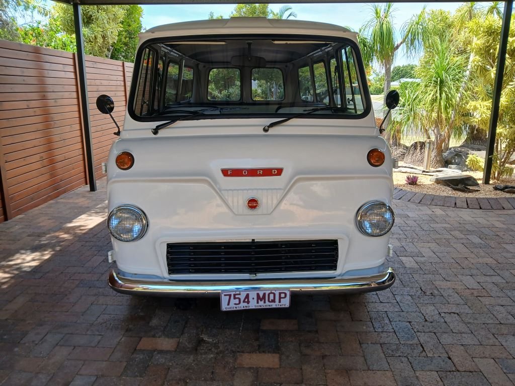
Okay, so today was bath day for the Thames and there were some mixed results in terms of the effectiveness of the new rubber strips that I fitted to the top of each door last Friday. The good news is that the door tops are now perfecly sealed. The bad news is that we are still experiencing water ingress down each side of the door. So I'm thinking that I need to run the same seal down each side of the door just to where the window ends as depicted by the red lines in these photos: Running 3 separate sections of seal on each door with tatty looking corner joints will send my OCD into overdrive, so I'm going to experiment with a few leftover offcuts to see if I can make a decent looking piecut for each of the 90 degree bends. If I can achieve that I'll bin the existing bits and stock up on some fresh lengths next time we do a town run. However, it's not all doom and gloom as yesterday we did a fairly long drive at speed and both Mrs Flash and I noticed that we have lost an annoying whistling wind sound that I had always assumed was coming from the sliding glass door windows. Turns out it was air coming in the top door gap that the new seal has solved. So one more for the win column. In other news I've been searching for a while for a new nose badge to replace my current one which as you will see in this image is looking a bit crusty: It's the only badge on the entire van that hasn't been replaced with a new one. This particular badge is pretty rare as they were only fitted to the vans assembled outside of Dagenham, in other words those vans supplied as "knocked down" kits to other countries. This image shows my badge and the 3 other nose badges that were fitted to the UK assembled vans: Sharing some useless information with you all - the badges depicting the 10/12 and the 15 refer to the CWT (hundredweight) loading capacities and the 800 was another derivative of the van. I have encountered a few NOS examples of the "15" badge on eBay UK, but as I said my badge is rare as. A few months ago I put the word out on the Thames 400e FB page that I was looking for a good nose badge, but have had no luck tracking one down thus far, so today I broke down and asked Mrs Flash to give my existing badge a bit of a birthday with some enamel model paint that I bought a while back. It's not perfect, but it looks way better than it did: And it looks even better from a few feet away: Thanks for reading.

- 740 replies
-
- 22
-

-
Well done on the WOF. What an amazing result. I've been following your Marina journey from the start and must compliment you on the way that you have phased this restoration. From a motivational point of view it's way easier to tackle the beautification phase on a vehcile that is already running and road legal. Too many folk dive straight into the paintwork and bling and then run out of steam when they realise that on top of this time consuming and financially draining bit they still have all the mechanical work to face. I'm looking forward to the next phase of your journey. Happy motoring.
-
I've clocked up another 125km on the old Thames in the past two weeks and she is purring along like a kitten. Gave her a good wash and a polish last week and noticed that when I hose her off I'm still getting a bit of water ingress along the tops of the front doors which sprinkles the seats and wets the floor mats. Bloody irritating. A closer look at the current pinch weld seals that am using around the door openings revealed a slight gap along the top of the doors. I could replace the seal with a fatter profile, but that will be too much down each side meaning the doors will be a bugger to shut properly. I probably could fit the fatter seal along the top edge only, but my OCD would battle to come to terms with mismatched seal profiles and nasty looking joints, so something more cunning was required. Scratched my head for a bit and then decided that a neater looking option might be to fit a second seal to the top section of each door. So while we were in town yesterday I wheeled past my local rubber place and picked up 1.2 meters of my favourite half moon rubber seal. Gave it a quick trim, peeled off the backing and stuck a piece along the top of each door like so: Profile shot: And with a bit of luck that should improve the situation. I'll know for sure next time I give her a bath.
- 740 replies
-
- 11
-
-
The old Thames has clocked up another 560 km this month. Fuel consumption and overall engine performance are back to normal since I fitted the remanufactured electronic distributor, so that is a bit of a relief. The a/c is also working like a charm, but I had noticed a bit of sideways play in the idler pulley when I replaced the compressor a month back, and rather than faffing about with a new bearing I decided to replace the whole pulley. Splashed out on a genuine Dayco unit which set me back a cool $39.50 including postage. Part number for my records: Quickly whipped out the old unit and sat it next to the new one for a quick comparison. The housing on the new unit on the left has a bit more shape to it, but the pulley diameter and the position of the bearing are identical. Chucked the new jobbie back on the van, adjusted the belt and fired it up for a look see. Belt runs perfectly true so I'll take the win.
- 740 replies
-
- 10
-
-
I'm with @igor on this one in terms of NZ manufacturing. The Thames would definitely have arrived in NZ in "kit form", but that's not to say that NZ would have been forced to follow the "CK" prefix on the serial number. So your "L" prefix could well be an indication that your Thames was assembled in NZ. It would be interesting to hear from someone in the USA to find out what letter prefixes their serial numbers for the vans assembled in the USA and Canada. I see that you have already posted a question on the 400E FB page and with a bit of luck Sandy Glenn may spot your posting. Sandy is a walking encyclopedia when it comes to the 400e.
-
Thanks for reaching out Steve. It's always good to hear from a fellow 400e owner. I don't know much about the numbering convention used by Dagenham for the UK assembled 400e, but those assembled outside of the UK have a rather interesting numbering scheme -apologies if I am telling you stuff that you already know, but here goes: First up is the chassis number that is punched into the vertical surface on the RHS chassis leg about 100mm forward of the body to chassis mount as can be seen in this photo: Although not too clear in this image, this number starts with "400E" and is actually a match for the engine number. Next up is the vehicle identification plate located in the footwell on the LHS of the cabin which looks like so: This plate is what passes for the modern day equivalent of a VIN number and the main clue apart from the "Ford Motor Company of Australia" banner is the first part of the id number prefix. If your prefix starts with the letters "CK" then that is a definite sign that your Thames was assembled outside of the UK. The CK stands for "Completely Knocked Down" meaning that the vehicle left Dagenham in pieces (kit form) and was assembled elsewhere. The remaining digits in the serial prefix may well provide a clue on the actually country of assembly, but unfortunately that is where my knowledge ends. I hope that this has helped you in some way.
-
No matter how small or insignificant the job seems, it's always a good day when you get to tick an item off the snagging list. Some of you may recall that I fitted a Mitsi L300 wiper setup to the old Thames earlier in the year. As part of that task I had to cut and shut the wiper arms to suit and I ended up using small 3mm diameter nuts and bolts to fix the Thames ends to the Mitsi arms like so: Well suffice to say that every so often I've had to retighten the nuts as things worked themselves loose. I've had visions of a wiper blade parting company mid stroke and the remaining part of the arm gouging a nice track in my unobtainium windscreen, so earlier this month I ordered in a pack of the smallest diameter pop rivets that I could find. Even better was that they were coated black so no need for me to faff about with a rattle can. Picture of the win: I had to ease the holes open an extra 1/2mm to accomodate the new pop rivets, but it's all done now. The snag list is now down to 24 items.
- 740 replies
-
- 12
-
-
My usual a/c guy has raised his regas price by 33% so I voted with my feet and found a different place further along the road that is still charging the old price. Really nice guys and the service was way more professional so they will be getting my business from now on. And that's hopefully the last of my a/c related issues.
- 740 replies
-
- 19
-
-
This morning I cracked into the fitting of the replacement a/c compressor. First step was to remove the manifold from the old compressor. It looked a bit manky, so I gave it a quick spritz of degreaser followed by a light dose of sandpaper before fitting it to the new unit. It's not mint, but it looks better than it did. There is limited space between the engine and the chassis rail as can be seen here: So the process for refitting goes as follows: Step 1 - Stick the 4 mounting bolts through the compressor (there is not enough room to fit these bolts later) Step 2 - Reverse the compressor into the gap and push it hard against the chassis leg like so: Step 3 - Reverse the mounting bracket into the gap between the compressor and the engine like so: Step 4 - install the 4 bolts that hold the bracket to the side of the engine. Step 5 - Tighten down the 4 previously inserted compressor through bolts. I then chucked on a fresh drive belt, connected the hoses to the manifold and connected up the clutch engagement wire. And that's the compressor done and dusted. She's a pretty tight one as can be seen in this photo: With that done, all that remained was to replace the reciever/drier bottle with a fresh one: Last step was to reinstall the radiator, engine box lid and side panels and the air deflector plate and she is back on the road. I'm booked in for a re-gas at 10am on Friday, so hopefully that goes well.
- 740 replies
-
- 12
-
-
Thanks fellas, I'll check them out. Might be worthwhile me pulling the box while I'm about it as I've got a weeping rear main seal that I've been ignoring for a while.
-
Funny you should mention the exhaust. When I first heard the noise I thought something had broken loose inside the LHS muffler as it sounded exactly like that, a bit of a tinny sounding rattle. I'll have a good check underneath tomorrow.
-
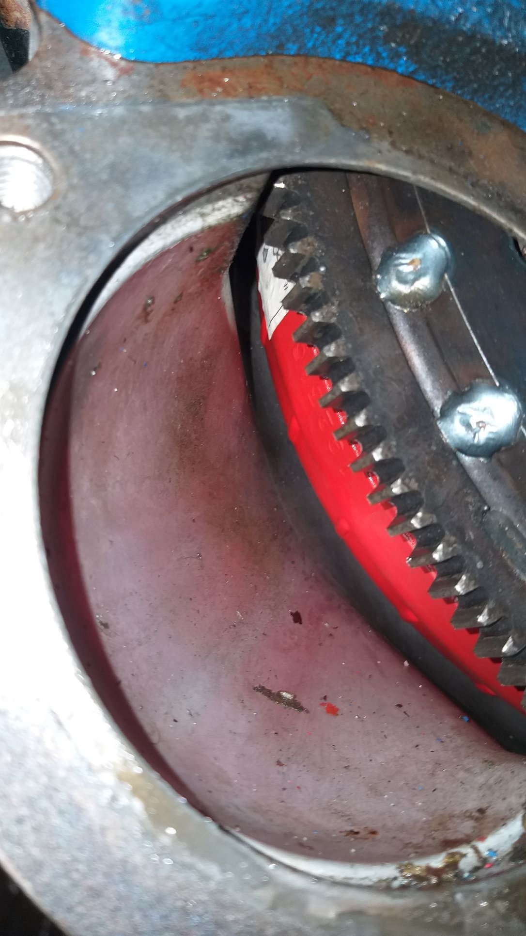
From memory the only inspection point without removing the tranny is by removing the starter motor. I had the starter out earlier this year and took this candid shot at the time: If the mounts aren't the issue maybe I should pull the starter for another look.
-
Thanks, I'll check them out too.
-
Yep, fluid is clean. No burning smell at all. Driving the car it shifts nice and smoothly. Torque convertor is a Hughes Performance 2000RPM that was installed in 2013 and has done less than 8,000 miles. Between myself and the previous owner the car has never been driven in anger.
-
Thanks, good suggestion. I'll take a look at the mounts tomorrow.
-
Thanks mate, yep the sound is there when in gear but stationary and also when moving.
-
Hey All, I'm in need of some guidance on a new issue with my '66 Tang. All of a sudden the C4 tranny has started making a rumbling sound when in gear. It sounds a bit like an exhaust resonating. Noise goes away when in park but comes back when I select any of the forward or reverse gears. Fluid is clean and is at the correct level. I'm not sure what's causing the issue, but it sounds bloody expensive. Any help would be appreciated. Ta in advance.
-
Just before morning smoko I got a message from Jeremy to say that my new a/c compressor was ready for pickup, so after a quick cuppa I saddled up the Moke and moseyed on through to his place. Returned home with this pack of goodness: Much bling:
-
While I'm awaiting the arrival of my new a/c compressor, I thought I'd tackle another a/c related issue. My underdash unit is fed from a 30 amp fuse. If I turn the blower fan off and on using the switch on the unit everything is hunky-dory, but if I leave the blower running and switch off the ignition key, the fuse sometimes blows when I switch the ignition back on. I'm guessing that the inrush current is just too much for the blade fuse. It's bloody irritating. So a few weeks back I sourced a 30 amp auto reset circuit breaker and I decided today was the day for fitting it. Didn't fancy working upside down under the dash, so started off by unwrapping about 8 inches of wiring loom right at the fuse panel in order to free up enough slack then unbolted the whole panel and let it hang down for a closer look. Not much space left on the front of the panel to mount the circuit breaker, so I ended up fixing it to the back lip like so: Refitted the panel, reinstated the spiral bind and then put the ignition switch through a good few cycles with the blower on high. Oh, the absolute joy. And that's another item knocked off my snag list.
- 740 replies
-
- 12
-
-
Those of you that have been following along on my journey may have noticed that my van has an insatiable appetite for distributors. So just to refresh everyone's memory here is a brief history: Distributor 1 - a conventional points based distributor sourced off eBay for around $100 which lasted less than 50km before the shaft disintegrated. Who would ever have thought. Distributor 2 - an original Toyota points based distributor that I fitted all the eBay distributor's internals to and that lasted 440km before dying a sudden roadside death. Again no surprises there. Distributor 3 - distributor 2 fitted with Repco's finest replacement condensor which managed an incredible 87km before giving up. Distributor 4 - an aftermarket Chinese manufactured electronic distributor sourced earlier this year from a reputable Australian based supplier that managed an impressive 1106km before calling it a day. And that pretty much brings us up to date. So a little more detail about distributor 4. When I fitted it the van ran okayish, but seemed a little down on power and quite a bit heavier on fuel. I also noticed a slight hesitation at low revs which got progressively worse towards the end. Then about a month ago while out enjoying our usual Friday night burger run the van wouldn't start. A quick diagnosis and no spark at the plugs. Luckily we were close to home so I left Mrs Flash and our wee dog in the van and walked back home to fetch the Moke. Got back to the van just as the sun was setting and phoned my mate Steve the towie. Steve was attending a BBQ and I felt bad disturbing him so told him I'd make another plan. I had a towing strap with me and considered using the Moke to pull the van home, but something prompted me to give the van another go and she fired straight up. Mrs Flash climbed in the Moke while I nursed the van home. Although running the engine was behaving rather badly with a misfire and she wouldn't rev at all. We stumbled along and finally made it home. Next morning the van fired straight up and rev'ed cleanly ... WTF. Next day ... wouldn't start and again no spark at the plugs. So at that point you can imagine I'm cursing like a sailor while trying to figure out my next move. Knowing that new Toyota units are no longer available, I figured that the next best thing would be to get my hands on an original Toyota unit that I could have professionally rebuilt. Now it just so happens that I have this little puppy in my stash of parts: Looks well used and the shaft was almost completely seized on it, but it is a factory original and I figured that someone more knowledgeable than myself could bring it back to life. My first stop was the auto sparkie in town. Bruce is old school so I figured he was a good bet. Sadly he informed me that he no longer dabbles with distributors. Bugger... Back home I hopped on the Google and discovered a place called Performance Ignition Services based down in Victoria. Dropped them an email with a few photos including this candid shot of the dizzy with its pants off: Got a friendly call back from one of their technicians to confirm that they could rebuild it for me, so I popped it in a box and dropped it in the mail. And that brings us to this Friday when a parcel arrived containing one much healtheir looking factory distributor. So after removing my faulty a/c compressor in anticipation of the arrival of it's new replacement I cracked straight into the fitting of the dizzy. It fitted easily enough and the van fired straight up, but when I came to set the timing with my light I discovered that for some reason I didn't have full adjustment. Moving the distributor housing clockwise was causing something to jamb up despite there being plenty of travel left on the slotted mounting hole. WTF.... On closer inspection I discovered that the outer corner of the integrated coil pack was snagging on the hard fuel line. Pulled the dizzy out again for a closer look at the fuel line and ...... Some numpty had mounted the fuel line too high up by using the incorrect hole on the arrowed mounting tab resulting in the circled portion of the hard line being higher than it should be. That line has been like that forever, so it's funny that this didn't cause any hasstles with the aftermarket dizzy. Anyhoo, pulled off the nut, wiggled the bracket down into the correct position and reattached the nut: And now the hardline no longer clashes with the dizzy. Slapped her back in the hole, tweaked the angle till my timing light was happy and she runs like a champ again. Couldn't run it for too long as I still have the radiator out, but I'm hoping that my dizzy woes are finally over. Thanks for reading.
- 740 replies
-
- 14
-
-
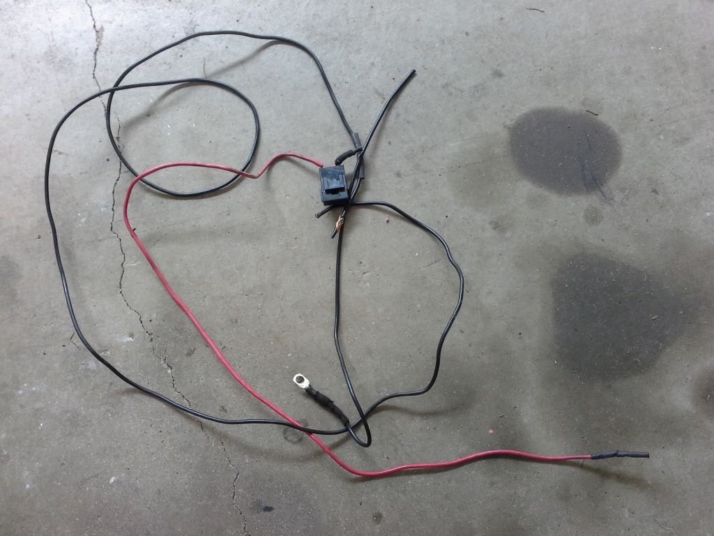
Today I managed to make a start on the a/c repair. First order of business was to remove the radiator to gain access to the a/c compressor and belt tensioner. The good news is that the idler pulley for the tensioner runs true and is pretty smooth. The bad news is that there is heaps of sideways play on the compressor pulley and it feels pretty rough when spinning it. So in summary I reckon my a/c guy was correct with his diagnosis. The Toyota Landruiser HZJ series use the same compressor so luckily my local a/c parts supplier has a replacement compressor on his shelf. With a bit of luck I can pick it up from him early in the new week. I'll replace the receiver/drier at the same time. While I have the radiator out I thought I'd remove the defunct power feed for the thermo fan. Some of you may recall that I ran a new feed earlier this year, but recovering the old feed meant unwrapping the wiring loom which is a helluva lot easier with the radiator out. Spent the rest of the morning removing the power lead and rewrapping the wiring harness, just to appease my OCD tendencies. And now ready for the bin:
-
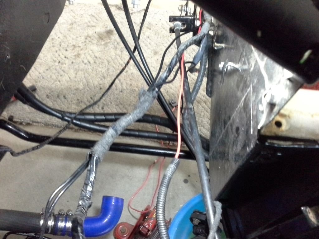
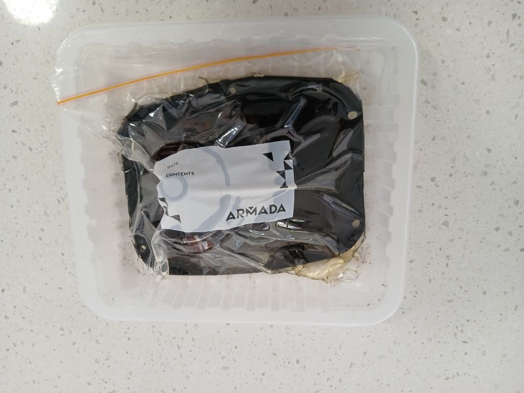
Many moons have passed since my last Thames related catch up, so I guess it's time that I updated you all on the latest happenings. Over the past few months we have been driving the van heaps, but to take full advantage of the cooler months all of our spare time has been focused on getting some things done around the house and garden. The result has been no time to tinker on the van, but I have been adding a few items to my "to do" list. Now that the days are starting to warm up, it's time to start executing some automotive related activities. First major thing on the list is to deal with cabin temps and some of you who spotted my posting under the tech forum a few months back will have already heard this story, but for those who haven't here is a repeat: The short story goes as follows. On hot starts I would need to crank the engine for a good 20 to 30 seconds before the engine would fire. After eventually firing into life the engine would stumble along for a few minutes before settling down. I suspected that we were experiencing fuel vaporization and started a tech topic to gather suggestions on possible cures. As is always the case a number of wise old schoolers provided some suggested solutions which I gave due consideration. At the end of the day I took the lazy way out and have now wired the main thermo fan switch to permanent power. The result is a thermo fan that now runs independent of ignition power. Not only has this solved our fuel vaporization issue but it has also decreased the air temperature in the cabin when parked up after a long run and the strong aroma of "hot engine" inside the cabin has also gone. I'm thinking that the mighty 3Y and its mechanical fuel pump was unhappy with the coziness created by the miniscule engine box that the Thames is blessed with. This fix has been in place for a few months now and is working well so I'm going to leave well alone for now. The next major item is to sort out our a/c related issues and this is getting critical now that the weather is warming up. So when I last talked about the a/c I was experiencing excessive drag on the drive belt which was shedding rubber flakes like confetti and was needing adjusted after almost every drive. I eventually ended up removing the drive belt and we have been without a/c through the winter. I suspect I've either got an issue with the tensioner pulley or the pulley on my second hand compressor. I did ask the opinion of my a/c guy and he immediately said a/c compressor but I'm hoping this isn't the case as that is an expensive fix. Anyhoo the only way to get to the pulleys is to remove the radiator so I made a start on that today. With the wind deflector under the engine removed I started off by draining the radiator and while that was happening I took the opportunity to unbolt the gear shift cover which can only be done from underneath with the wind deflector removed. The reason I wanted to remove this is to solve another irritating issue which is a creaking sound that comes from the rubber gear shift gator which is especially bad in colder weather. The gator is an old Cortina MK1 that my mate Grant donated to the cause, but the rubber is pretty hard and I suspect that is half the problem. Did a bit of googling and a NOS rubber goes for over $300.... yikes, so I started looking up some old wive's cures and one suggestion is to soak the rubber in WD40 to soften it up. So after pulling it off I popped it in one of those zip lock sandwich bags and sprayed a whole heap of WD40 into the bag. Google says to remove as much air as possible from the bag and to then let the rubber marinade for a few days, so I was able to squeeze out quite a bit air before sealing the bag. Looks like so: Over the weekend I'll get some time on the a/c and will keep you all updated on my findings. Thanks for reading.
- 740 replies
-
- 12
-
-
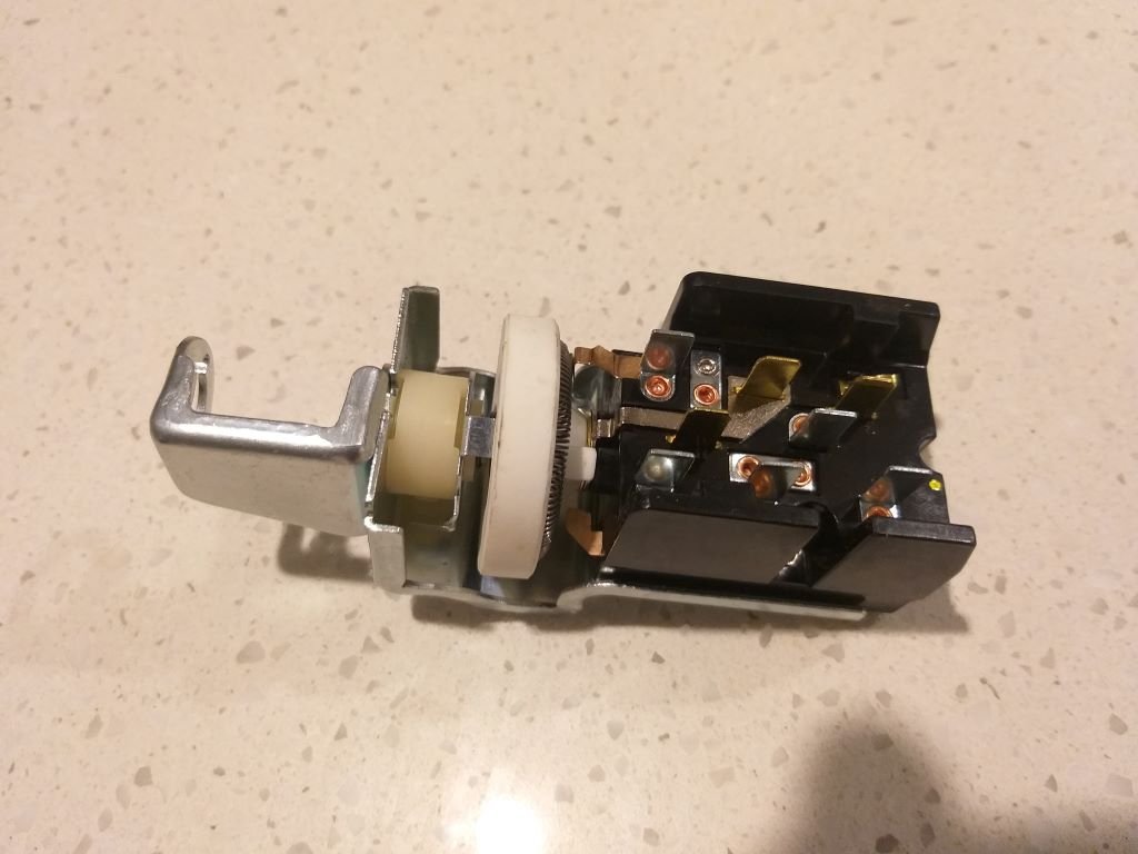
Waited a week for my new ignition switch to pitch up. Opened up the box and: Instant fail. Seller was most apologetic. Turns out the packaging for a light switch is identical to the ignition switch and someone had made a boo boo. Got the replacement in under 4 days so was happy with that. Hope this one lasts longer than the 13 months my last one managed.
-
Yep, that will work perfectly.
-
I used the same method to mount Falcon seats into my CF Bedford van about 10 years back. Cert man was happy with the mounts but he did ask me to add crush tubes inside the hollow sections.