Flash
-
Posts
1615 -
Joined
-
Last visited
-
Days Won
2
Everything posted by Flash
-
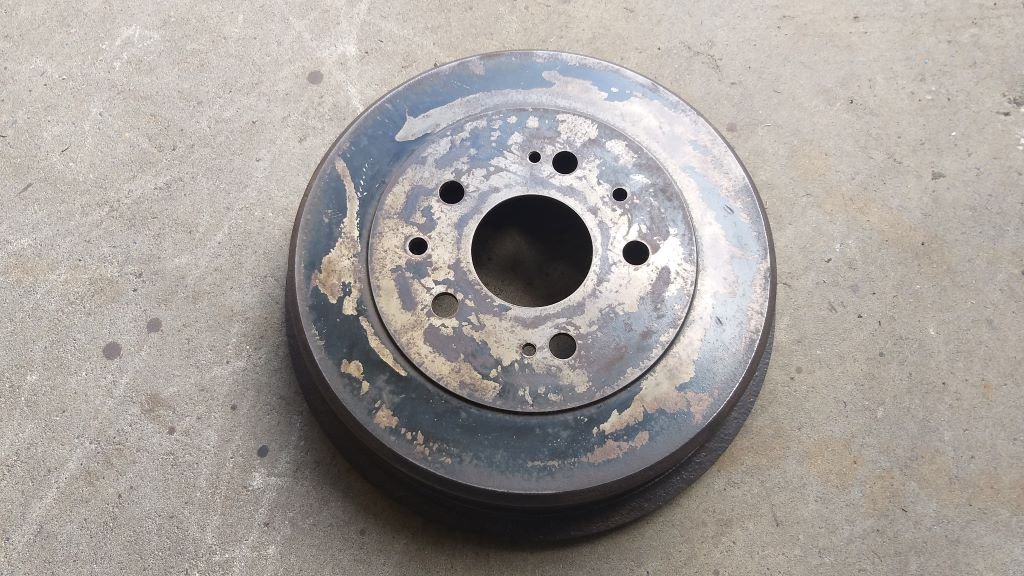
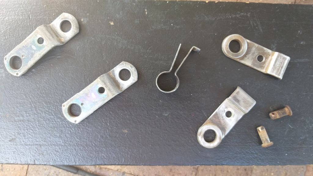
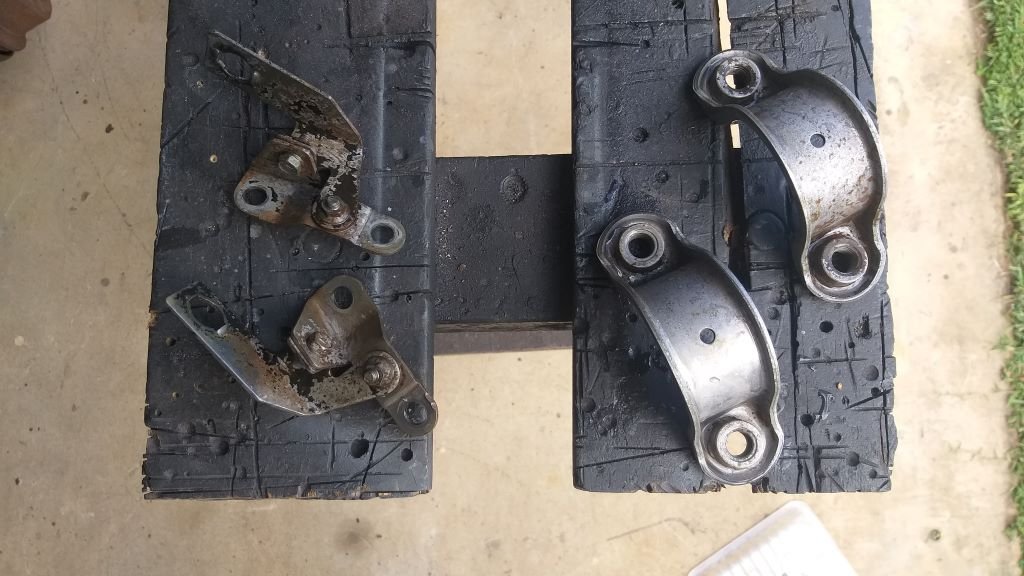
Vegetable eating day today. One you don't look forward to, but you know you'll feel better once you get through it. Used a combination of degreaser and the wire wheel of death to clean decades worth of crust off a few rear axle related parts. The smaller brackets are now languishing in the vinegar bath and I rewarded my efforts by splashing a bit of "eau de rattle can" on a few of the bigger parts. I'm hoping that the calliper paint will be okay on the rear drums.

-
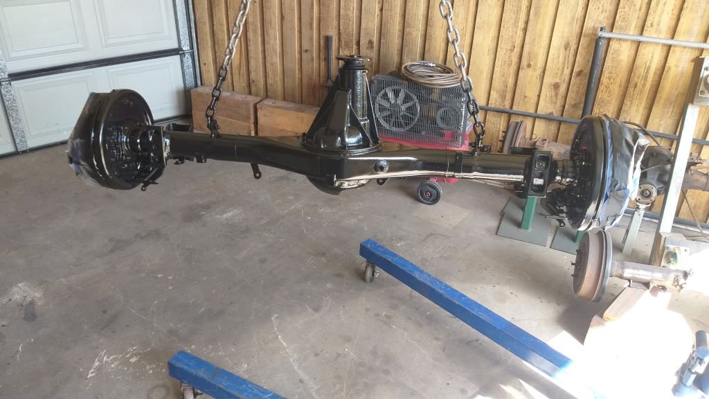
Slapped a few coats of 2K black on the rear axle today. In between coats I gave the gear selector cover a light tickle with some sandpaper so it's now ready for a splash of primer next time I've got a gun full.
-
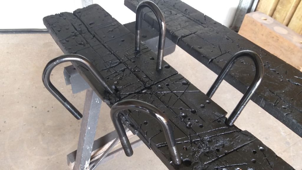
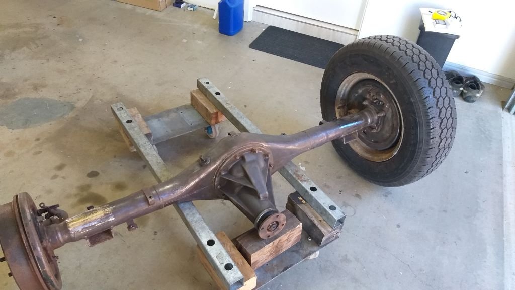
And that's the Thames spring perches and shock mounts all glued on to the HiAce axle. Celebrated the occasion by splashing a bit of primer about the place. One more coat of primer to go.
- 715 replies
-
- 11
-

-
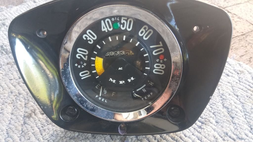
Speedo Cable - Chapter 4 With the way forward finalised all I need to do is give the cable a bit of a birthday before I chuck it in. Talking about that there is one minor snag. The cable needs to pass through an existing 19mm hole in the cabin floor. Only issue is that the plastic retainer on the Toyota cable measures 24mm so I'll need to open the hole up a bit with my step drill. Hopefully I've got an appropriately sized rubber grommet in stock. I'll only know how accurate the speedo reads once I've done a road test. There is a place in Victoria who supply a little calibration box that the hot rod boys use on the 5 speed Supra gearboxes and I'm hoping that one of these will work with the HiAce speedo drive. Time will tell, I guess.
-
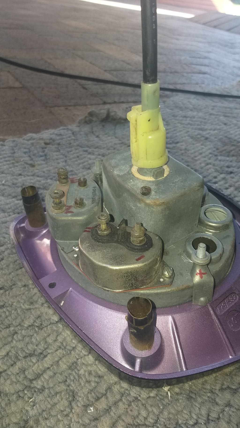
Speedo Cable - Chapter 3 I currently have the instrument cluster out for another round of wiring, so I figured it was worth seeing if the Toyota cable would fit into the back of the Thames speedo. Instant success! The square drive engaged nicely and even the moulded plastic bit on the HiAce cable clamps perfectly onto the speedo housing. Flushed with success I grabbed my battery drill and clamped the gearbox end of the inner cable into the chuck. Gave the drill a whirl and to my relief the speedo needle actually moves and is nice and smooth despite the fact that I haven't serviced the cable yet. I use the term speedo needle loosely as the speedo uses a little moving band to show speed. I’d forgotten this extra little piece of quirkiness. Yikes, I’ll definitely take the win. Photos to show the happenings:
- 715 replies
-
- 13
-
-
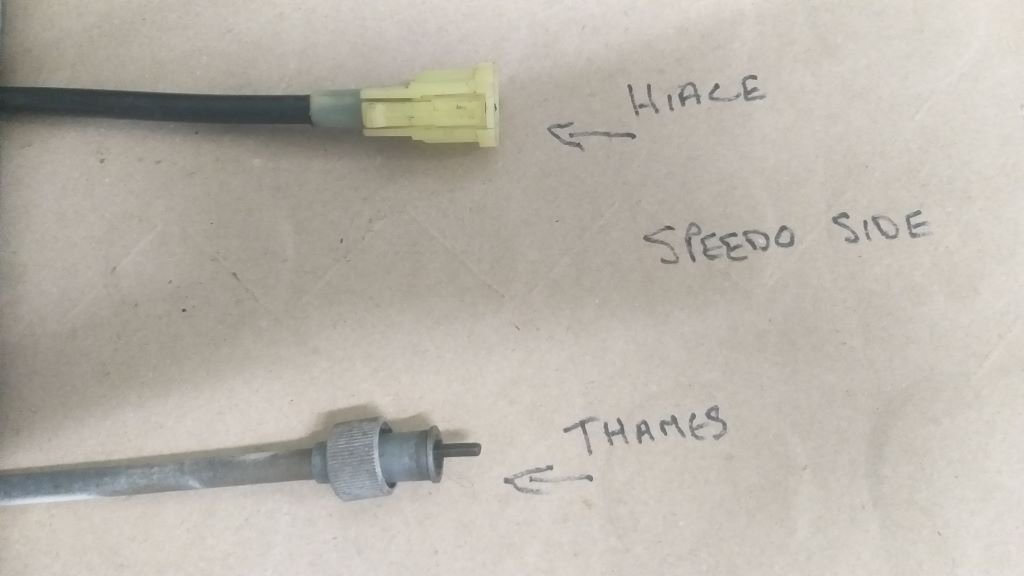
Speedo Cable - Chapter 2 Next I compared the speedo gauge side of each cable. Surprisingly the square drive on both inner cables look to be the almost the same dimensions. Who would have guessed? Looking at the outer sheaths the Thames one has a big nut whereas the HiAce one has a moulded plastic clamp. Again, side by side photo included below:
-
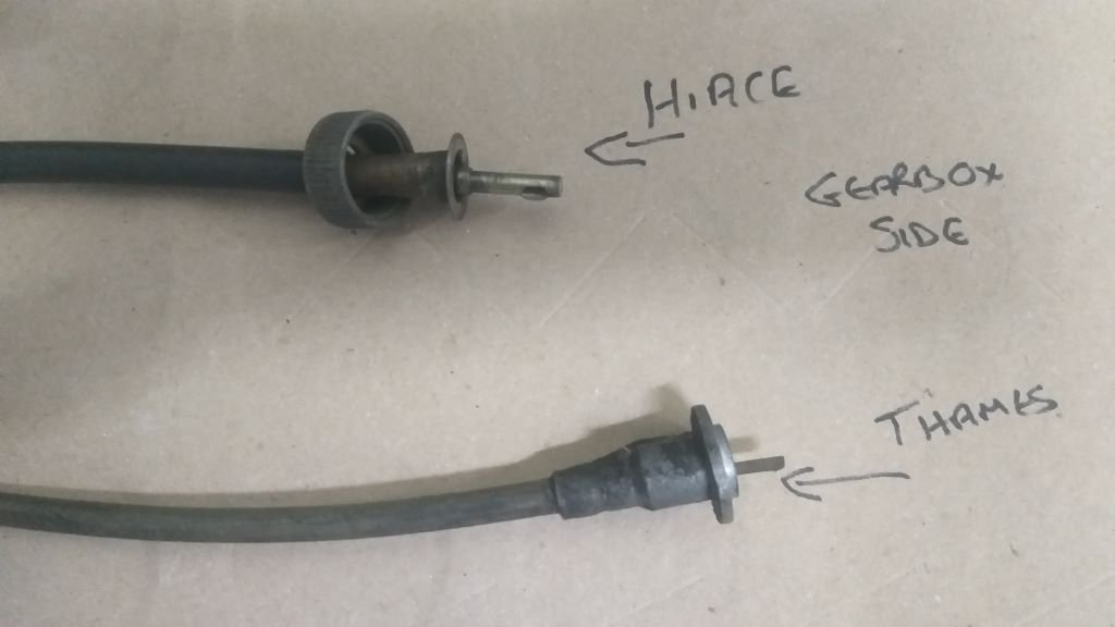
Speedo Cable - Chapter 1 I've been shying away from looking at the speedo cable for a while, but now that I am approaching the pointy end of the project, I thought I'd best put on my big boy pants and tackle the issue head on. Rummaged around amongst the shrinking pile of parts languishing in the back of the Thames and pulled out the original Thames cable as well as the HiAce one that I pulled from the donor van. Comparing the gearbox ends of each of the cables I can see that they are way different in terms of the way each inner cable terminates as well as the method for fixing the outer sheath to the gearbox housing. Photo below shows the two cables side by side:
-
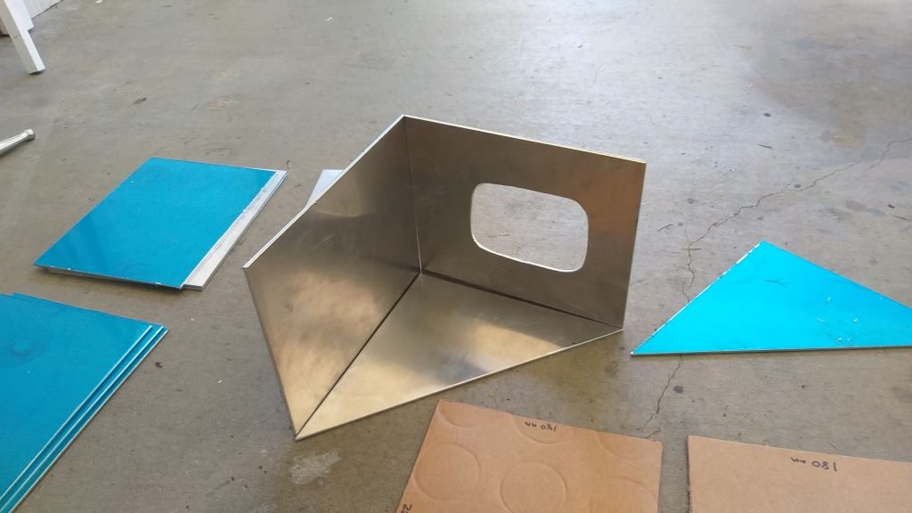
Just another fine example of the precision work undertaken here at Rough and Ready Restos. Last piece of the gear shift cover bonded into place:
-
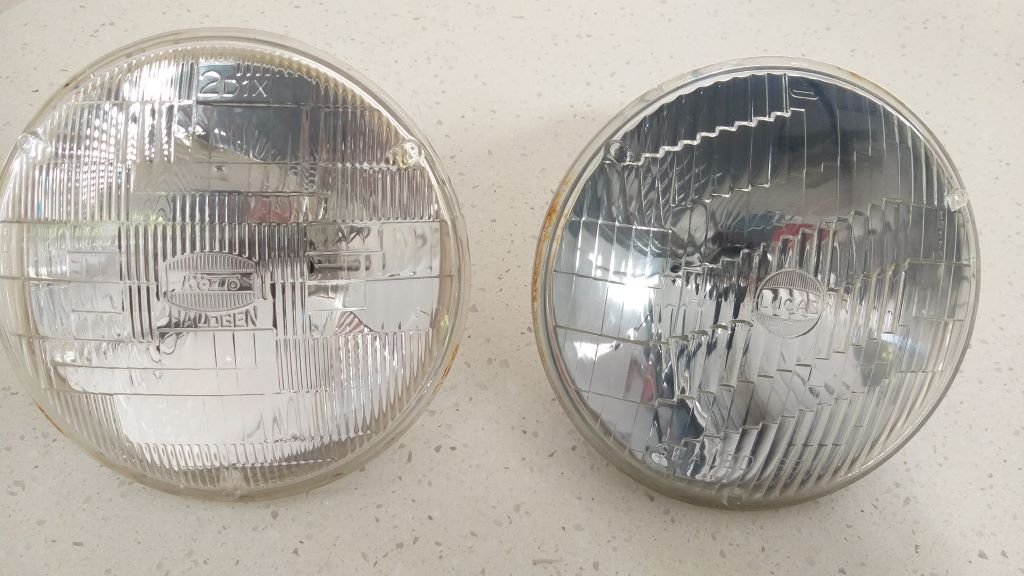
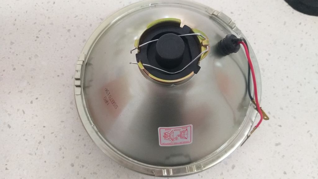
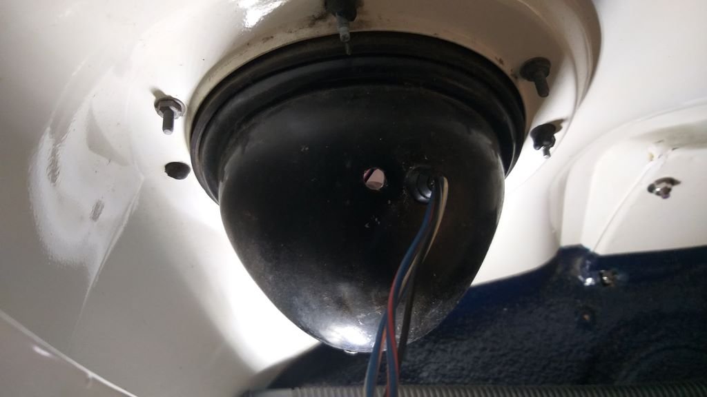
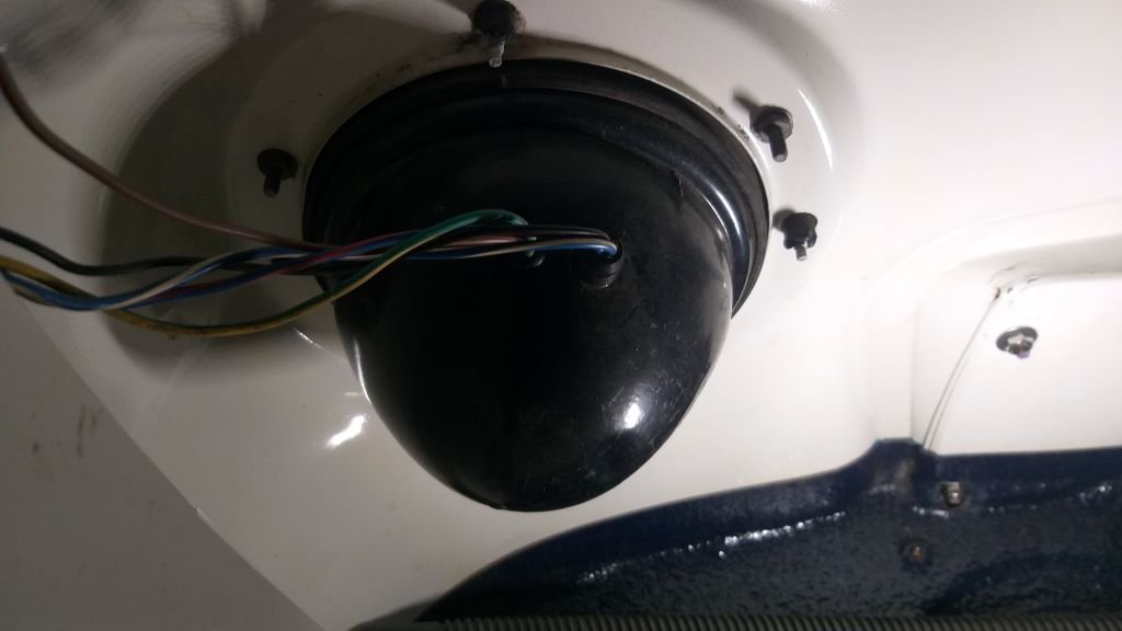
I'm still slowly plugging away at the gear selector cover. The issue is having enough space for the holding clamps whilst the panel bond goes off so I've been limiting the activities to one panel per day. I'm due to bond the last panel tomorrow, so should be able to show you my handywork on Thursday. In the meantime, I've been finishing off some electrical related items. Today's focus was replacing the original sealed beam headlights with H4 semi sealed units. The sealed beams were mismatched, and one had blown which left the van looking like it had a black eye. So the H4s will be a vast improvement. Originally the front parkers were incorporated in the turn signal lamps which use a double filament globe. I purposely bought the new H4 units that have the little park light built in to the housing, so this morning's task was to reroute the wiring for the parkers. I ended up drilling a second hole in the headlight bowls and have wired everything up. Just need to wrap the wiring. I'm thinking of using a small spiral bind rather than cloth tape, so I'll need to source some. Thanks for looking.
- 715 replies
-
- 11
-
-
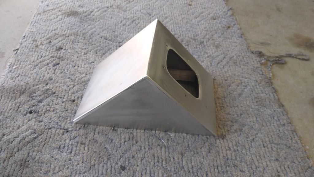
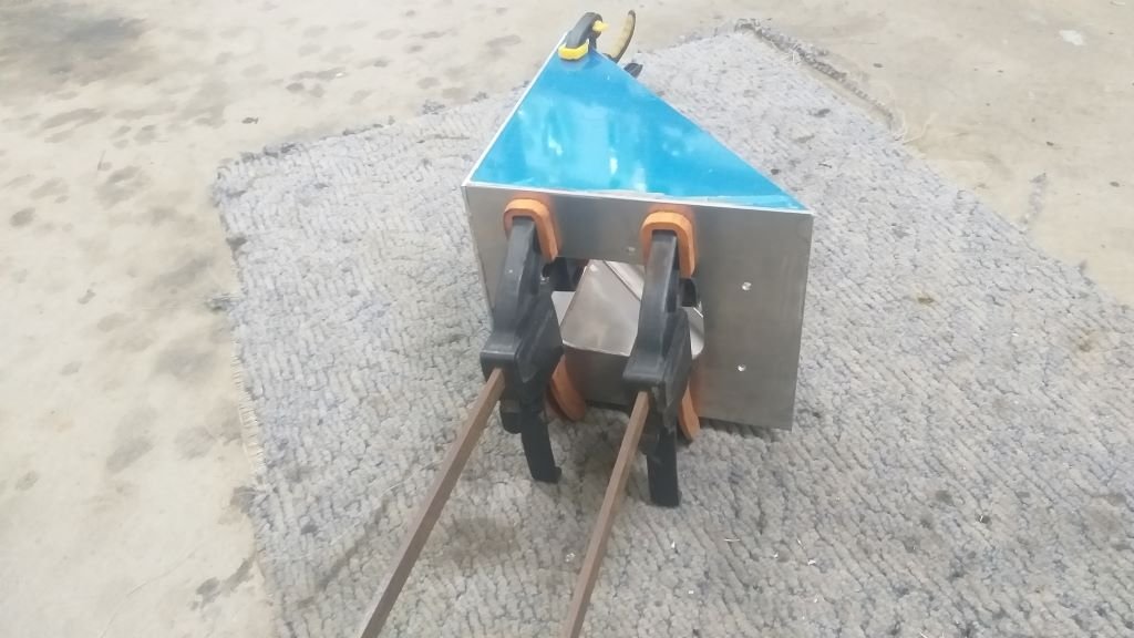
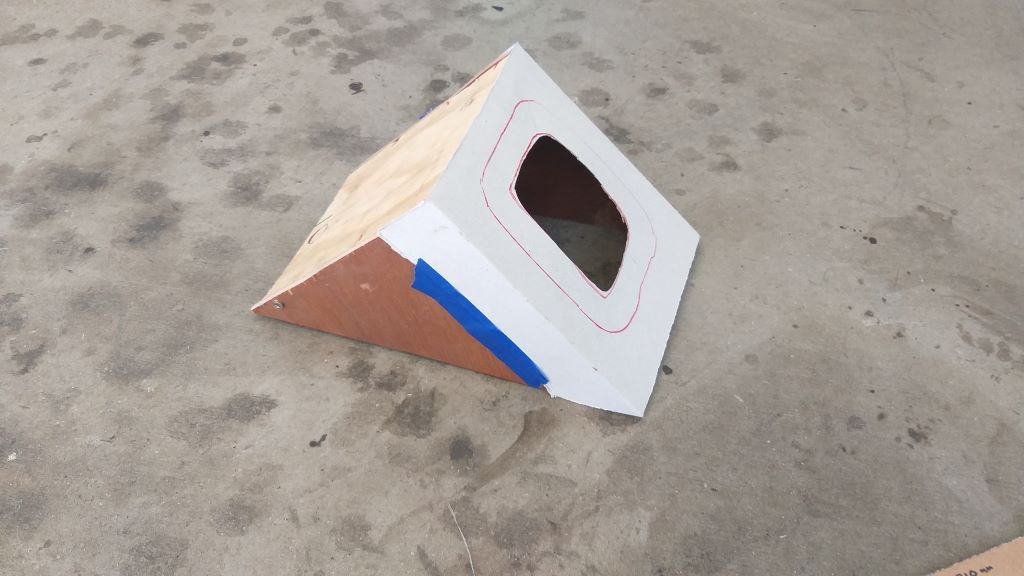
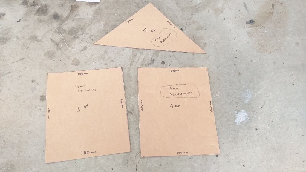
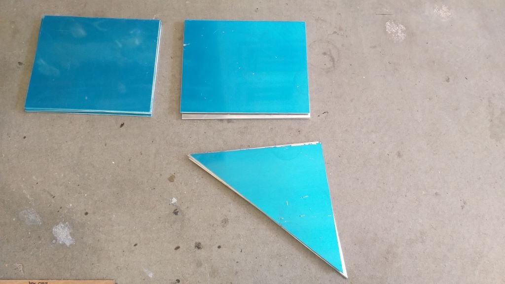
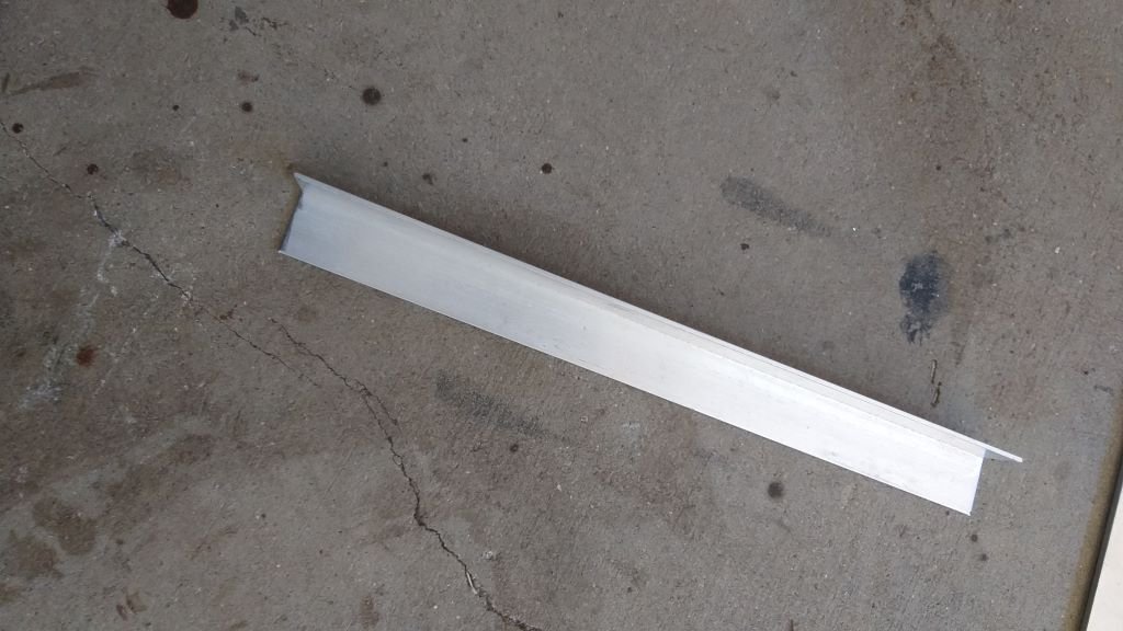
I didn't feel like dragging the welder out today, so thought I'd make a start on the gear selector cover. Earlier in the week my good mate Cameron swapped some 3mm aluminium offcuts for a bottle of red wine. I got him to guillotine me some spares in case I cock anything up. First step was to cut the opening for the gearstick out of the top plate. The plan is to use a small aluminium angle strip hidden on the inside of the panels and then glue everything together with panel glue.
-
Nice to see another Queenslander on here. Car is looking awesome mate.
-
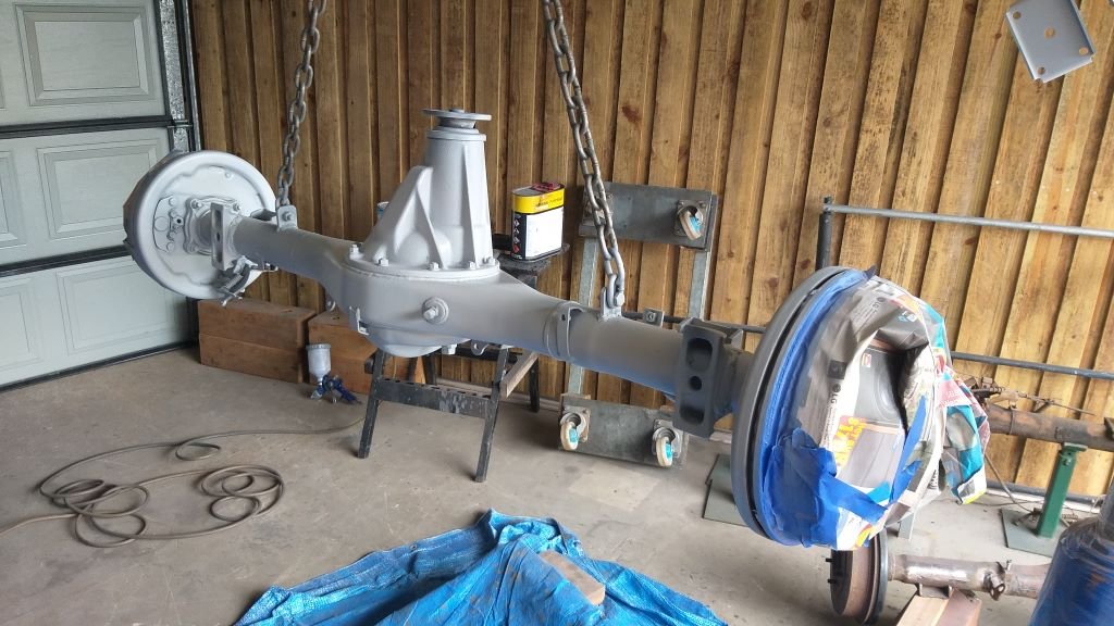
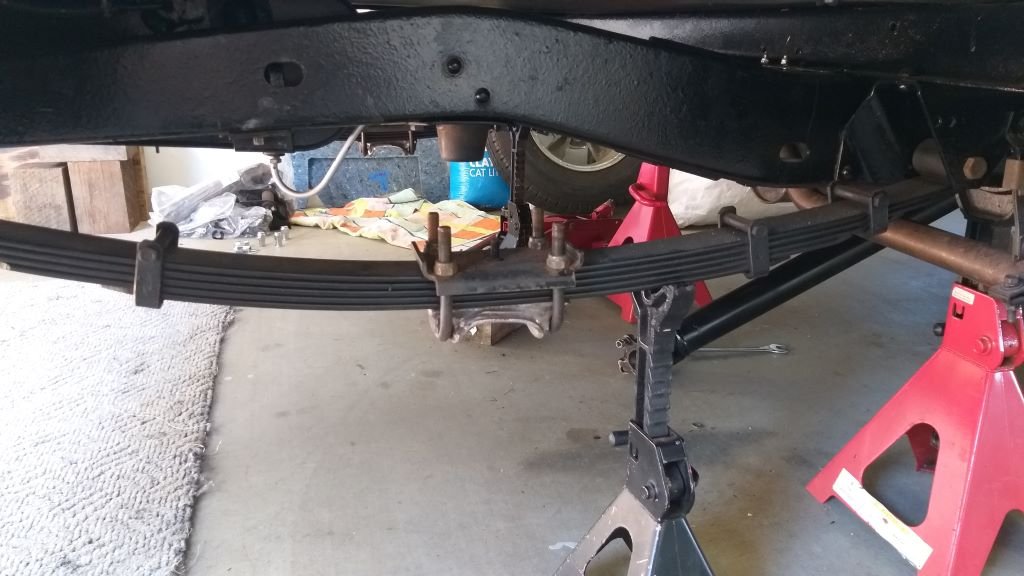
While I'm still trying to source a set of new rotors for the front I decided to crack on with the rear axle. Had to temporarily fit my front wheel hubs to get the van back on its wheels so that I could finalise the pinion angle. Then I used the dodgy straight edge that I cobbled together earlier to get the rear axle perfectly aligned. After taking countless measurements I'm now confident that the rear alignment is correct, so I've tacked the spring perches onto the axle and its back out again. Next step is to fully weld the perches.
- 715 replies
-
- 10
-
-
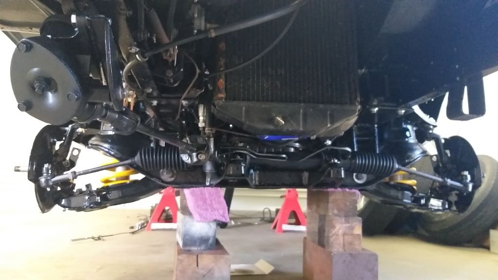
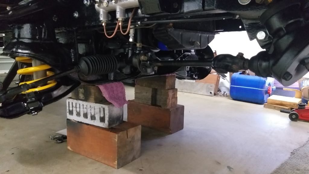
After morning smoko I cracked into installing the power steering rack and associated steering related bits. And that is another item ticked off the list. New ball joints and tie rod ends feel overly tight to me, but I still need to pump in some grease, so hopefully that together with some use will free them up a bit.
- 715 replies
-
- 14
-
-
And that's the other side done. I'm holding off on installing the hubs, discs and callipers for now as despite earlier reports I'm attempting to source a new set of rotors. My local spares shop says only one set left in Straya and they want moonbeams for them, so I'm investigating other suppliers.
-
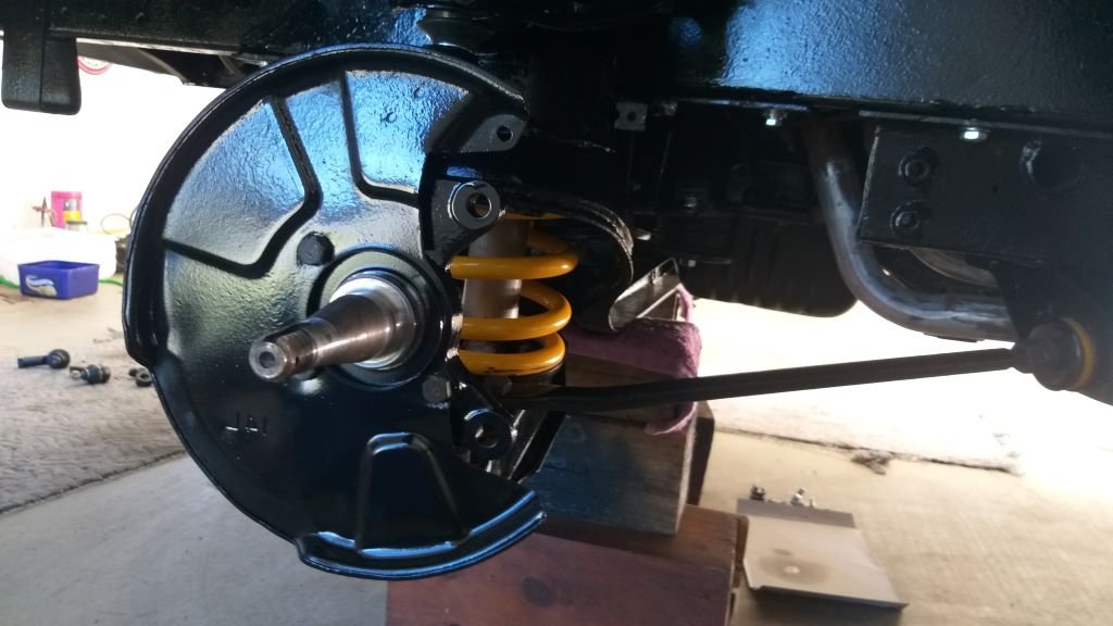
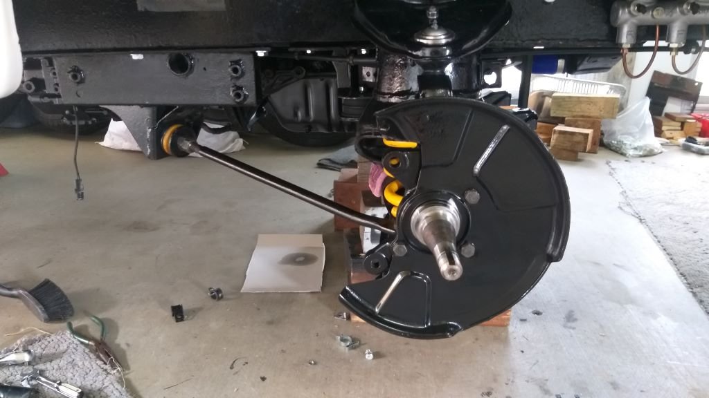
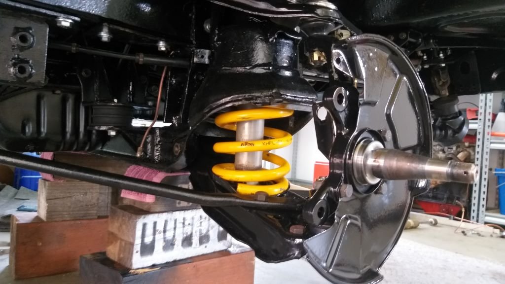
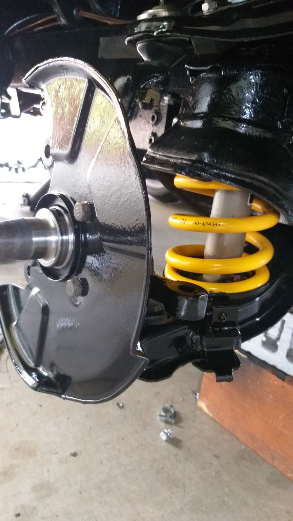
Thought I'd treat myself to something other than cleaning, sanding and painting today. Driver's side front assembly coming together nicely. I decided to leave the King Springs and Monroe gas shocks in their supplied colour for a little bit of contrast.
- 715 replies
-
- 13
-
-
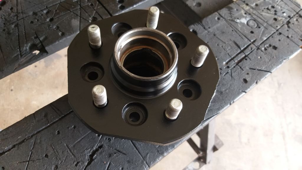
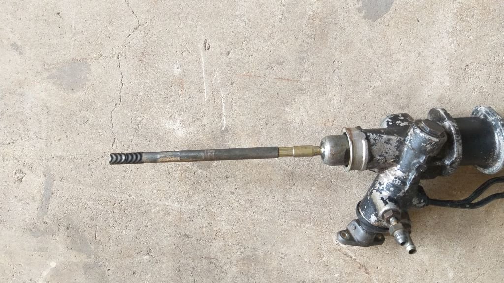
I got to drive the Mitsi Express donor van before I pulled it apart, so I know that the power steering rack that I am using is a good one. Gave it a good degrease and hit it with a bit of sandpaper before I treated it to a rattle can reco. Used that VHT brake calliper paint which goes on really well. Did the same to one of the front hubs whilst I was about it.
-
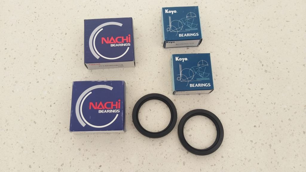
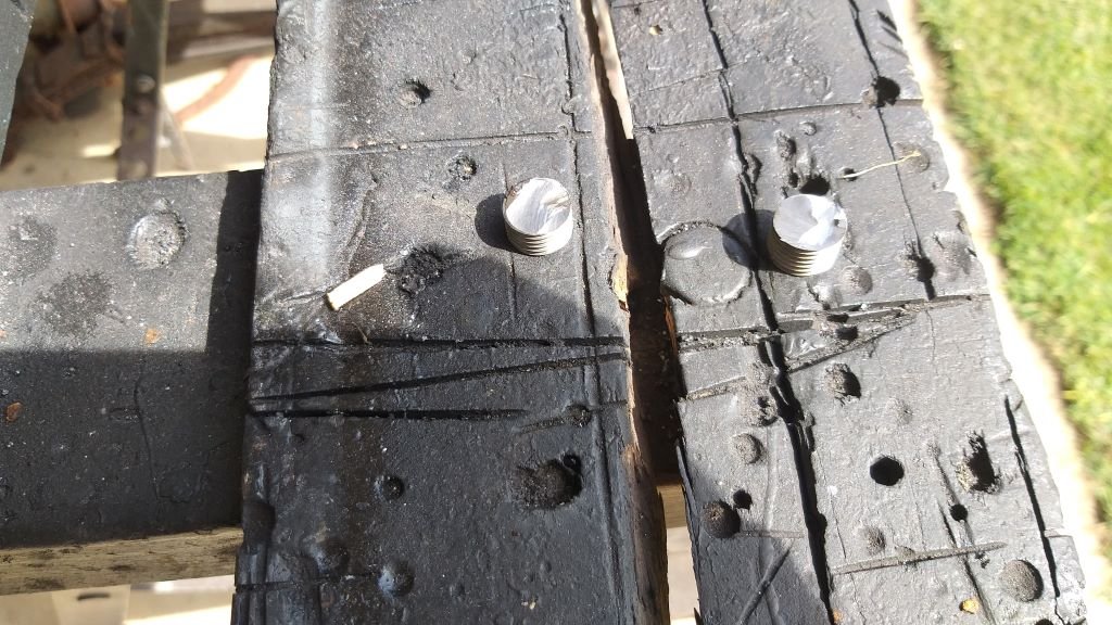
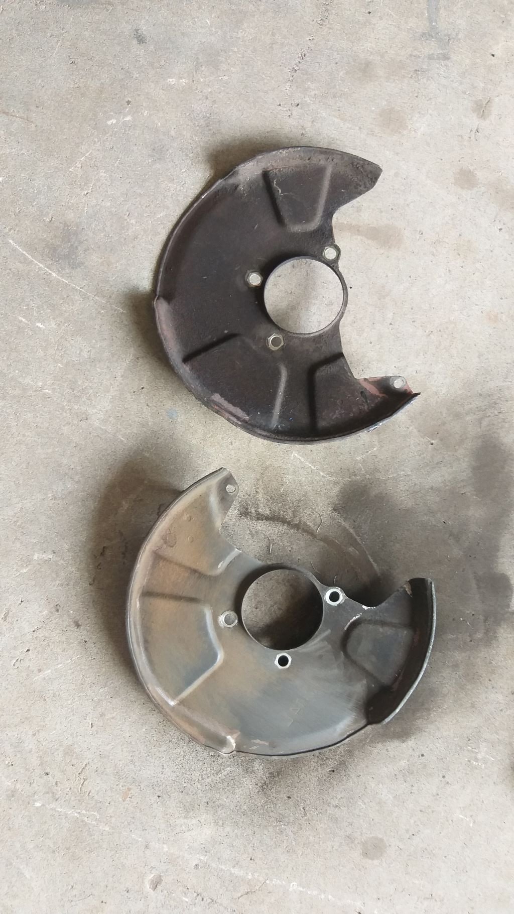
Earlier in the week we took a trip into town and I dropped by the brake specialist. We came up with a plan B for blanking off the two redundant outlets on my brake line junction. Hopefully this pair of 3/8 plugs will do the trick. Also took along my existing front brake rotors to see if I could get replacements. Bad news is that he had none in stock. Good news is that he took some measurements, and the existing rotors are still well within spec, so I'll just give them a clean up before I chuck them back on. Also dropped by the bearing shop and he was able to match up a set of front bearings and seals for me. Photos of the new bits because my life is quite sad:
- 715 replies
-
- 11
-
-
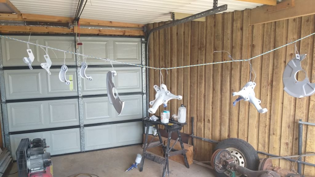
Managed to apply a few coats ok 2K black to my latest batch of parts today.
-
Brilliant, thanks very much.
-
What an amazing milestone. Well done. Engine sounds really good in that video clip. I really like your steering wheel too. What is it and where did you get it from ?
-
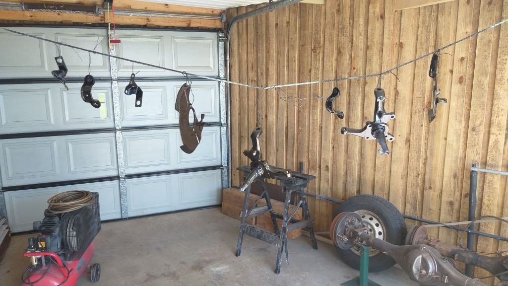
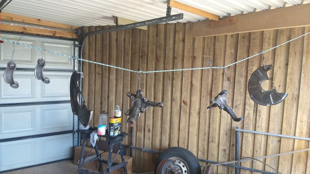
The neighbours are back at work today so I figured I could happily make a bit of noise and spray dust without pissing anyone off. They are good people so it's worth looking after them. My steering rack and brake line brackets spent another night in the vinegar bath, so came out as good as I am going to get them. Hit the stubs and backing plates with my wire wheel of death on my baby grinder and called them done. Got my washing line all hooked up and then gave everything a coat of primer after morning smoko. Wind is really pumping today but my back carport is pretty sheltered. Thought I'd post this update while I'm waiting for the first coat to dry.
- 715 replies
-
- 13
-
-
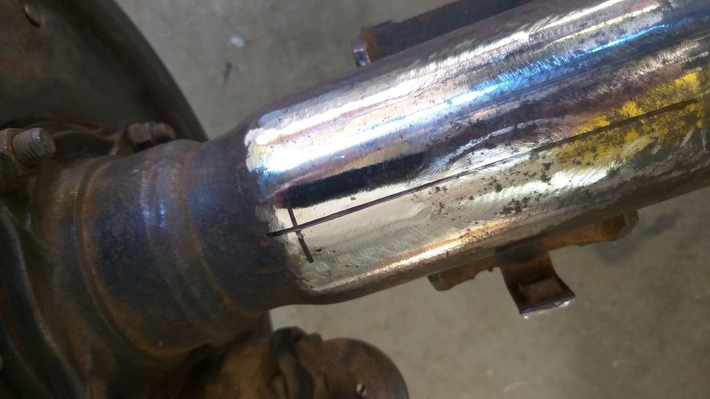
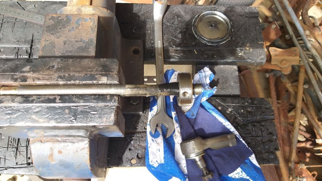
A good while back when I was setting up my toe in as part of the bump steer test, I noticed that my tie rods were right on the thread limit on the rack ends, probably due to the older series L300 suspension being slightly narrower than the newer version that the rack came from. Figured I'd sort this while I have the rack out for hopefully the final time. Grabbed a cheap and cheerful M14 x 1.5 die nut off eBay which arrived on Friday, so I thought I'd crack into it today. Cut an extra bit of thread on each rack end and then lopped 10mm off each end. And that's one more small item off the "still to do" list.
-
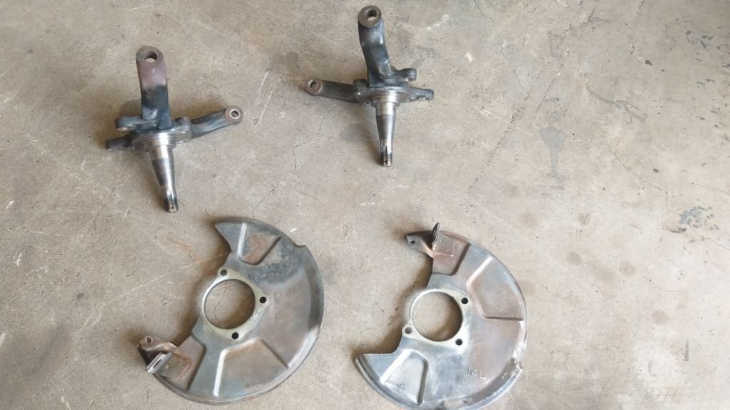
It being Sunday I thought I would give my neighbours a break from my angle grinder, so gave my stub axles and the disc brake backing plates a quick hand job. I'll give them a final tickle with a flapper disk tomorrow when everyone is back at work.
-
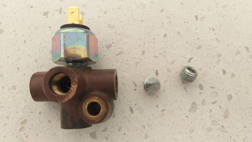
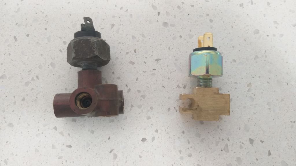
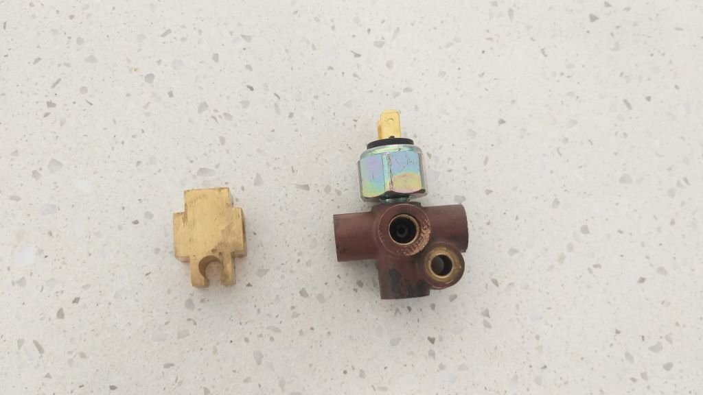
A few weeks back when I was testing my electricals, I noticed that my brake lights were staying on permanently. Like most of the British cars of its era, the Thames uses a small inline pressure switch to activate the brake lights. Turns out that these switches can go bad when left dry and they either seize up in the on or off position. They are a relatively cheap item, so I ended up ordering a replacement from a local Mini specialist. At the same time I thought I'd sort out the brake pipe junction that the pressure switch fits into. Now that I have converted to a dual circuit brake system I need to blank off two of the outlets on the brass junction, so on my last visit to town I dropped by our brake specialist hoping to get some blanking plugs. He suggested that I just replace the 5-outlet junction with a 3-outlet junction that he had in stock, so I grabbed one and headed home. And that is where things turned interesting. I couldn't get the new pressure switch to screw into the new junction. Rather than forcing it and running the risk of damaging the threads I decided to do a bit more investigation and its lucky that I did. Turns out that the thread on the pressure switch is not a 3/8 UNF as we had assumed but is actually a 1/8 - 27 NPT tapered thread. No wonder the pressure switch wouldn't fit the new junction. So, looks like I will be dropping by the brake specialist on my next town visit to see if we can come up with an alternate plan.
-
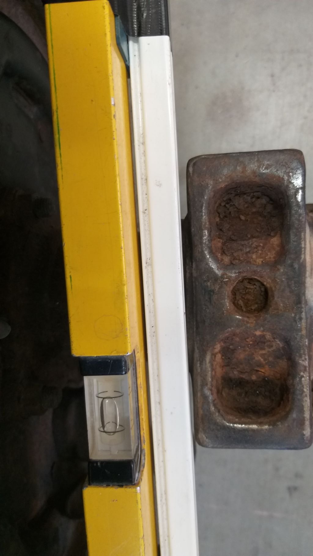
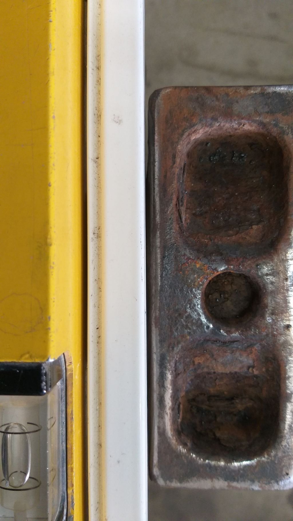
Rear axle alignment - Chapter 3 With the finest tool in the land safely in my grasp, I thought I'd start off by checking out just how bad my mock-up axle is. Chucked on the Mitsi wheel, waved my rough as guts straight edge about the place, used my cheap as digital vernier to get a fix and ....... Yep Right-hand spring perch is 1.4mm on the piss. Left hand perch is 0.7mm on the piss. And there we have the issue.