Adoom
-
Posts
2,279 -
Joined
-
Last visited
Everything posted by Adoom
-
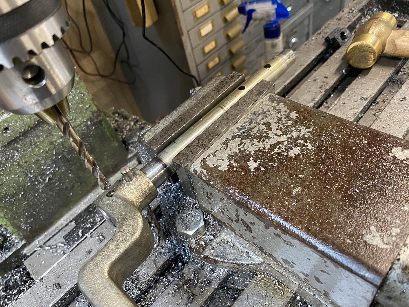
I finally got around to drilling the roll pin holes in the extended clutch pivot shaft thing. I used the existing holes to align it by adjusting it until I could lower the 6mm drill bit through the hole without it catching the edge. Here I have drilled the first hole and I'm using another drill bit to hold the arm so the next hole is in the right place. It all worked out fine.

- 52 replies
-
- 13
-

-
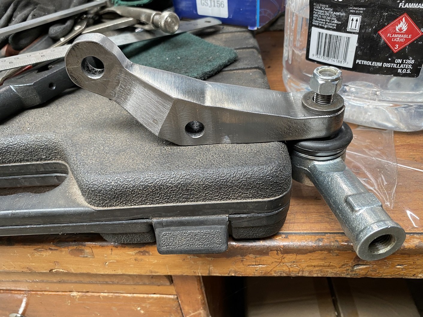
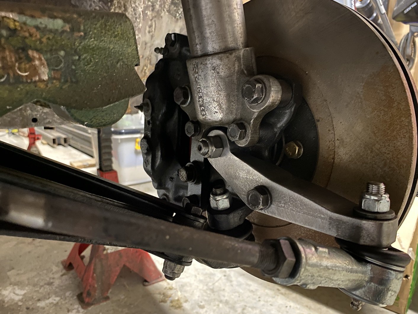
And the right side one is finished! It also fits! Both installed. This would be where full droop needs to be, any lower and the inner tie rod ball joint binds. There's another 60mm of travel to get to ride height. I guess I need to sort out doing a bump test now.
- 201 replies
-
- 11
-
-
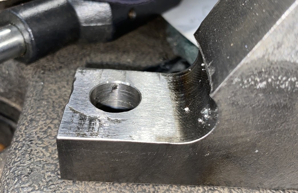
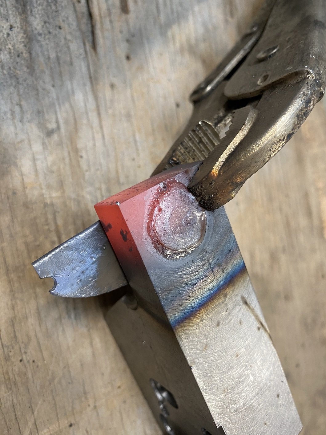
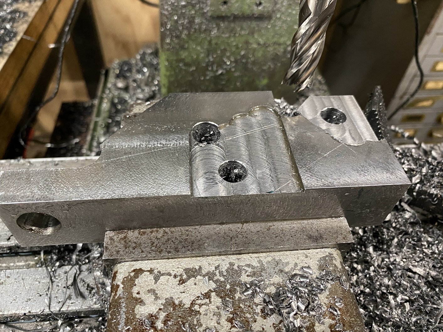
Turned the mig up to 11!..... or like 5, cause that's how far it goes. And installed the 0.9mm wire. Used a chunk I'd cut off to practice on. So, lets do this. I was concerned that the 20mm stick out would cause me issues getting penetration, but it was okay. Did some swirlys until the hole was full. Then flipped it over, ground it back a bit to clean it up and welded the other side too. Mill that weld off. This side is the important one because it's where the nut goes. Drill the hole again. Starting with a spot drill and working my way up from 5mm to 13mm. No issues with the weld being hard. Use the 13mm drill bit for "precision" alignment when clamping it down for reaming. The table is locked in position. And reamed it down just as far as the other one. I do have to use a washer with the nut, it seems that depending on which tie rods you get, the thread stops in a different place. This little black divot is the only imperfection in the hole from the welding.
- 201 replies
-
- 17
-
-
So the left side one is done. And it fits, thank fuck. The ball joint is not quite binding, there's a little left. The inner tie rod joint is binding, but this is at full droop and I intend to reduce the droop travel when I get around to making coil overs. I'll have to get on to trying to weld up the taper I messed up on the right side and try drill and ream it again. THEN I can see if I got the height right to fix the bump steer. If it needs fine tuning, I hope it can be sorted by spacing the rack up because I've got a little room there.
-
I procrastinated until 15:30pm before going out to the shed. Milled the mounting faces on the left side arm. I drilled a couple extra holes in the corners to make it easier to cut the profile on the bandsaw. But now it's time to make dinner. I'll probably do more procrastinating tomorrow.
- 201 replies
-
- 11
-
-
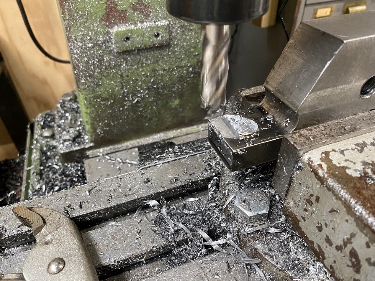
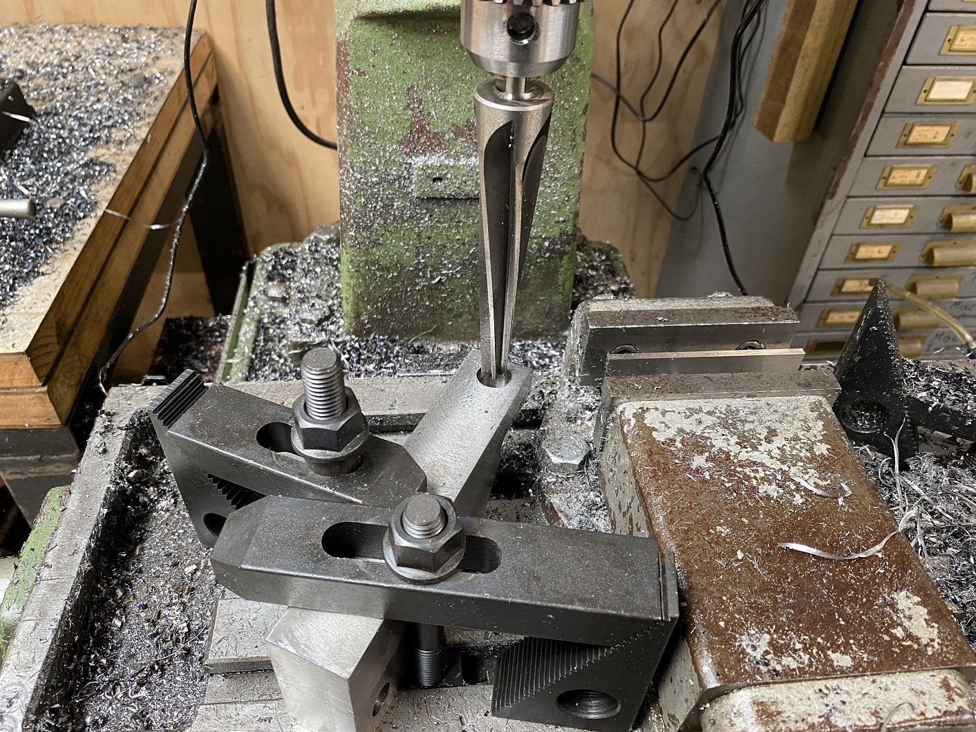
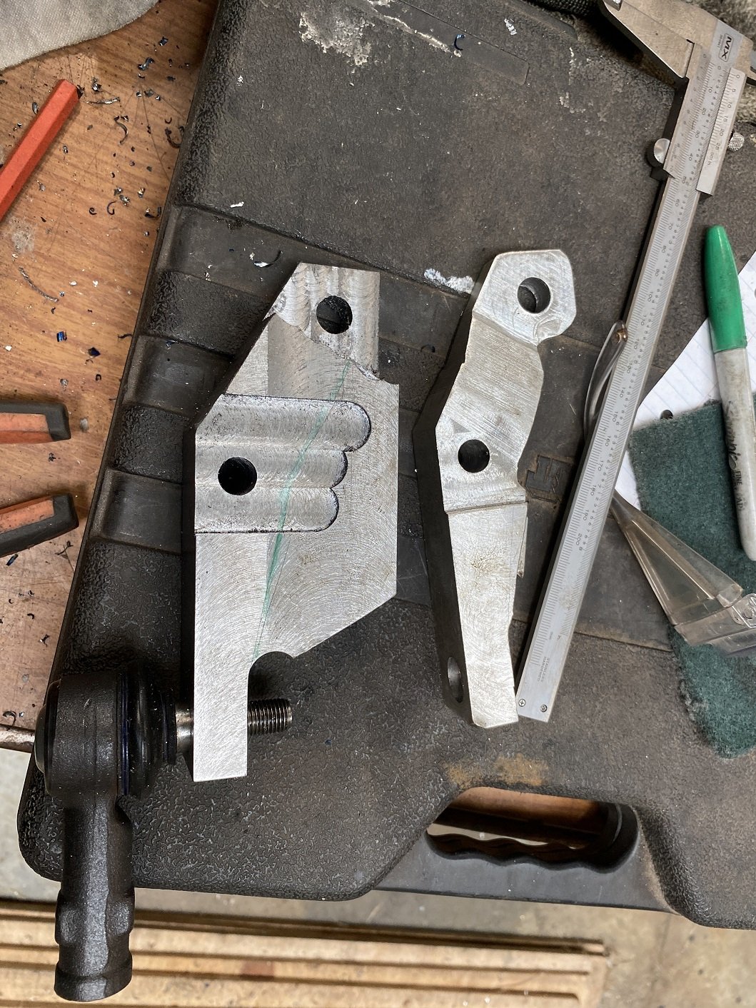
This is the one for the left side. I'll try weld up and redrill the hole in the right side one to try do the taper again, before I go making a replacement. I used the drill bit in the chuck to line it up on the table and clamped it down. The reamer just sneaks in. I put the mill on the slowest speed, 100rpm, used a bunch of lube and gently penetrated the hole. No problems with the taper this time.
- 201 replies
-
- 16
-
-
I learn all my machining from youtube and trial and error, advice and suggestions are welcome. Ah, okay, I initially just wanted to start the reamer in the drill press so it was straight and continue by hand with the big tap wrench so didn't clamp it down, just held it still, but I got overzealous with the definition of "start" and it grabbed and got a gouge in the side of the hole. I assumed the reamer would be able to clean that up, but I guess it just followed the gouge. I don't have a boring bar or boring head for the mill. But a boring head is on my wish list.
-
It's a 7 degree taper. https://www.amazon.com/gp/product/B07NMG3XWL/ref=ppx_od_dt_b_asin_title_s00?ie=UTF8&psc=1 Yes, I have a RF30 clone, a round column mill, so no knee, the Z axis is the quill, the whole head can be raised and lowered on the column, but it will also swing side to side so you lose any point of reference to the part. I have the head low enough that I can just reach the bottom of the part with the endmill. But the taper needs to be cut from the top of the part, and the reamer is 165mm long and has a shank with 3 flats on it to go in a chuck, not a collet, so that makes it even longer and it doesn't fit without moving the head. So I used the drill press to avoid moving the head. I guess I could just clamp the part directly to the table and that should hopefully give me enough room... And run the mill really slow. And use the fine feed, not the quill handle thing. It didn't feel like the reamer is being pulled in, the flutes are basically straight, not a spiral. It definitely flexes in the drill press.
-
I have a reamer, it's huge, had to get it from the US, cost me over $200. It is the correct taper because it machined a perfect fit taper in aluminium. I did it in the drill press, so it could have been too fast, or not enough pressure... or too much pressure. I think if I figure out the problem and try clean up the existing hole, the balljoint will go in too deep. Early on I did try machine the taper, but it was such an awkward shape to fit in the lathe and I could not get the taper angle perfect, so I bought the reamer(the CCM says it has to be reamed anyway). I think I'll have to try machine some test tapers in steel until I can make a good one before I scrap another thing I spent hours machining first. I probably need to go REALLY slow.
-
I'm loving the shape of that cab..... want an old truck now. I ain't got no inside space or money.
-
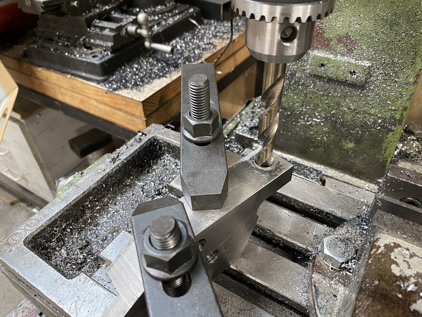
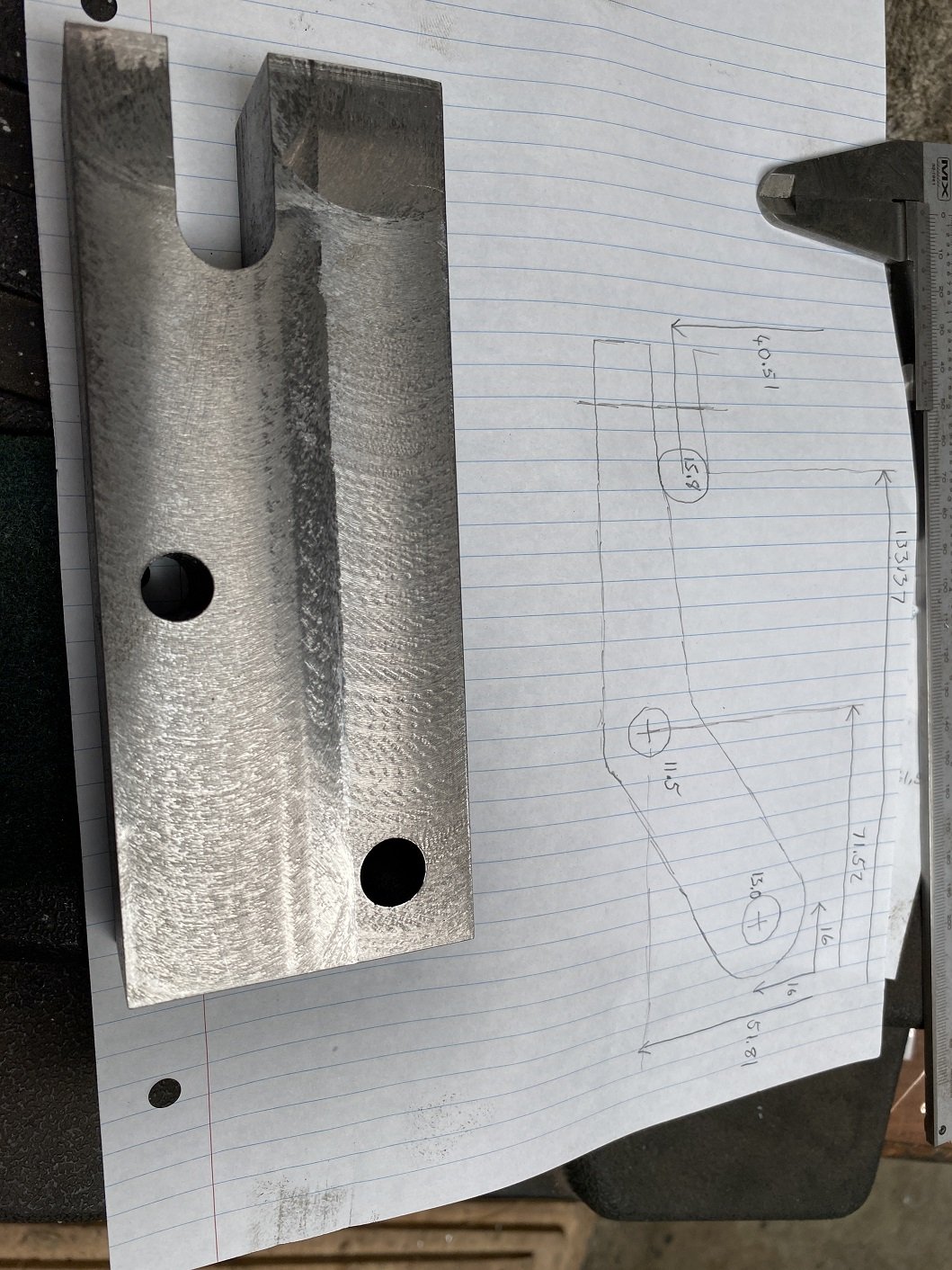
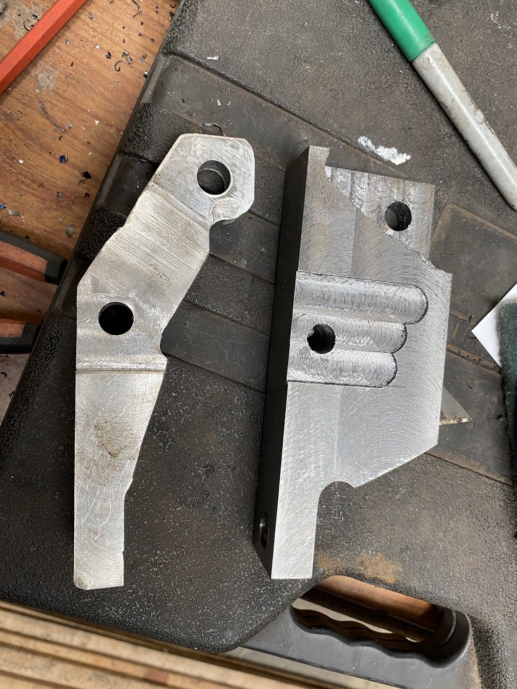
Made a couple of holes and a slot so I can cut the corner off so I've got space to fit the long 13mm drill. Here it is with the alloy prototype. I've drilled the pilot hole for the balljoint tapered hole. And milled the mounting faces to the right heights. Cut a corner off because I no longer need that bit as a reference surface. It takes aaaaaages to cut on the bandsaw. Buuuuuut, this one might be scrap When I reamed the tapered hole, it made an octagon and I'm not sure why. It worked fine on the softer aluminium. I suppose I could try build up the walls of the hole with weld, then re-drill and try cut the taper again. At least it wouldn't take as long as starting again.
- 201 replies
-
- 10
-
-

-
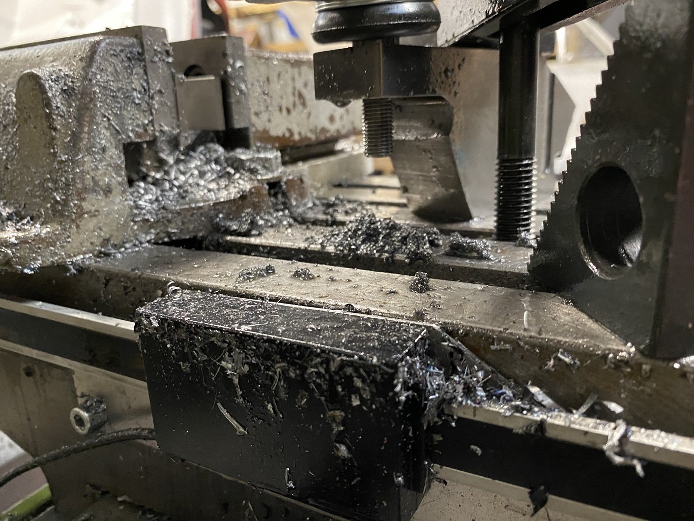
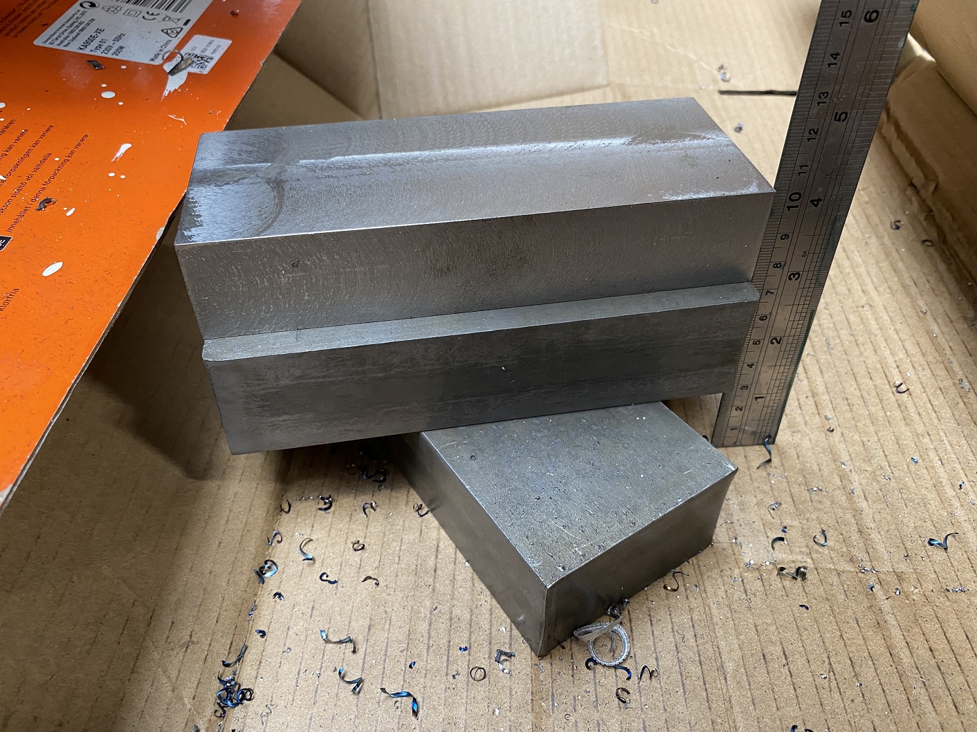
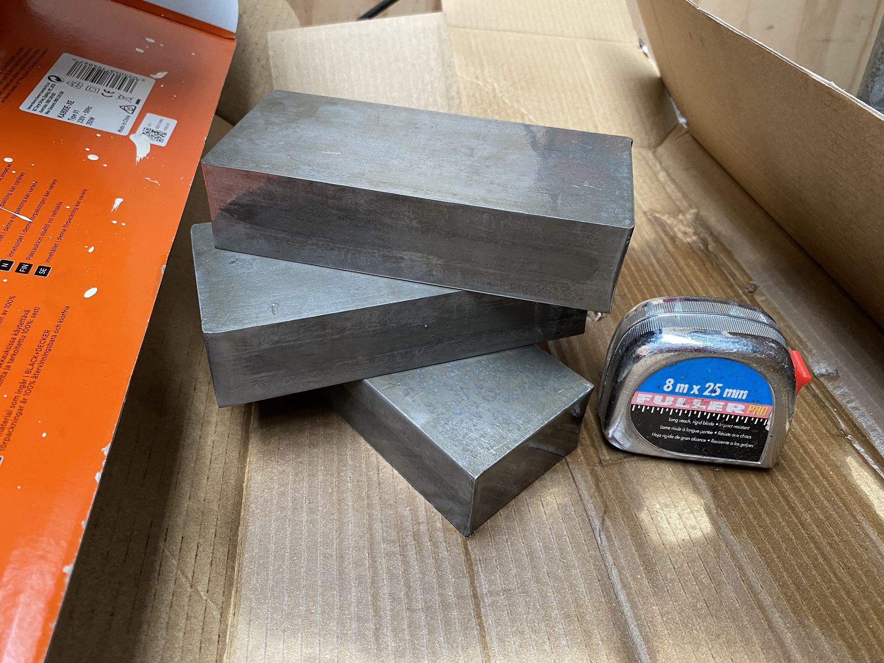
Finally put one of the steel blocks in the mill. At least 2 hours of face milling later, I faced all the long sides and got it down to the starting dimensions. It's pretty hot now. I took about 6mm off the face and one long side. I still need to mill at least one short end flat because I need to use it as a reference surface. I also made a mess. And melted some new holes in my gloves with hot swarf.
- 201 replies
-
- 11
-
-
Zip zap, it's in.
-
Making the other side. The milled cut-outs are to clear the raised sections of the floor. Ready to weld. Well I'd better go procrastinate some more and have a drink and update my OS thread.
-
Also, I finally got around to getting my modified steering arms. Some finishing work required... One spare, so I only get one chance to fuck up. I had some citric acid already mixed in a bucket, so I chucked them in there to remove the mill scale, because I can.
- 201 replies
-
- 11
-
-
It looks halfway between image 1 and 6. There is abrasion damage near the top of the rod that would have damaged the seal. I suspect VTNZ will fail it. I guess I must cross my fingers for working on car outside weather this weekend because my shed is full of projects and there is no room for the daily.
-
Are leaking shock/struts a wof fail? Or just a comment? New ones arrived today Ex japan, but I may or may not get a chance to fit them before the wof is due.
-
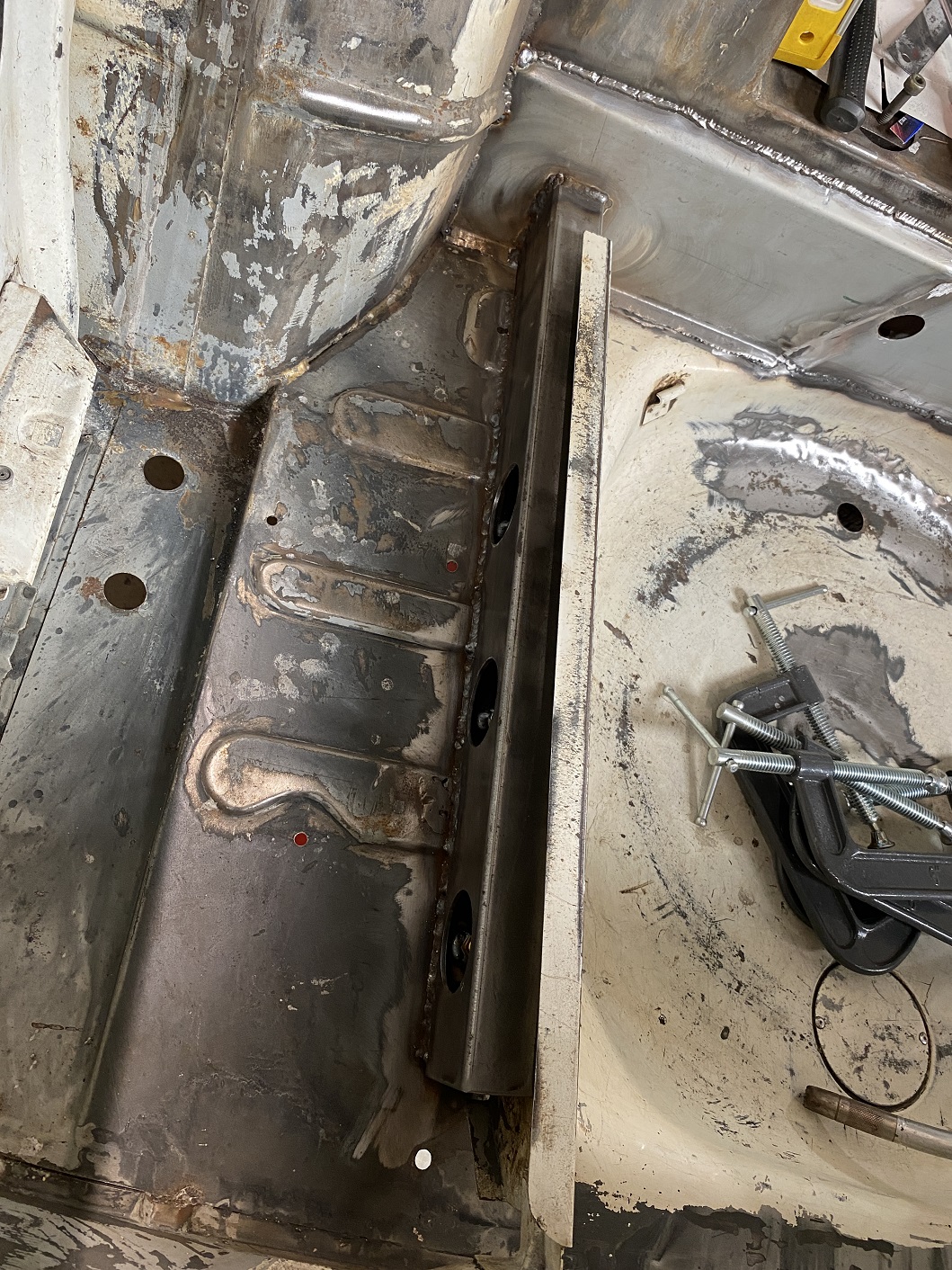
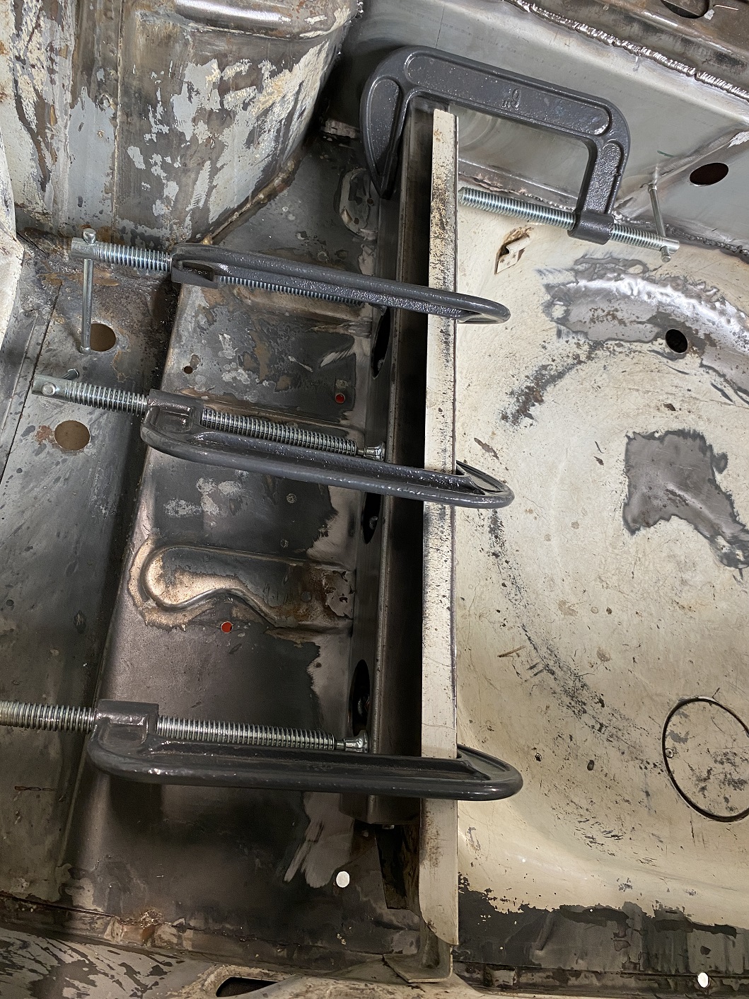
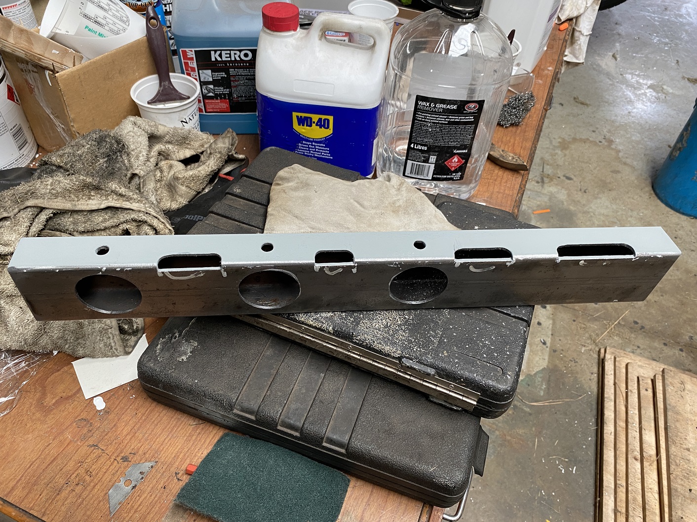
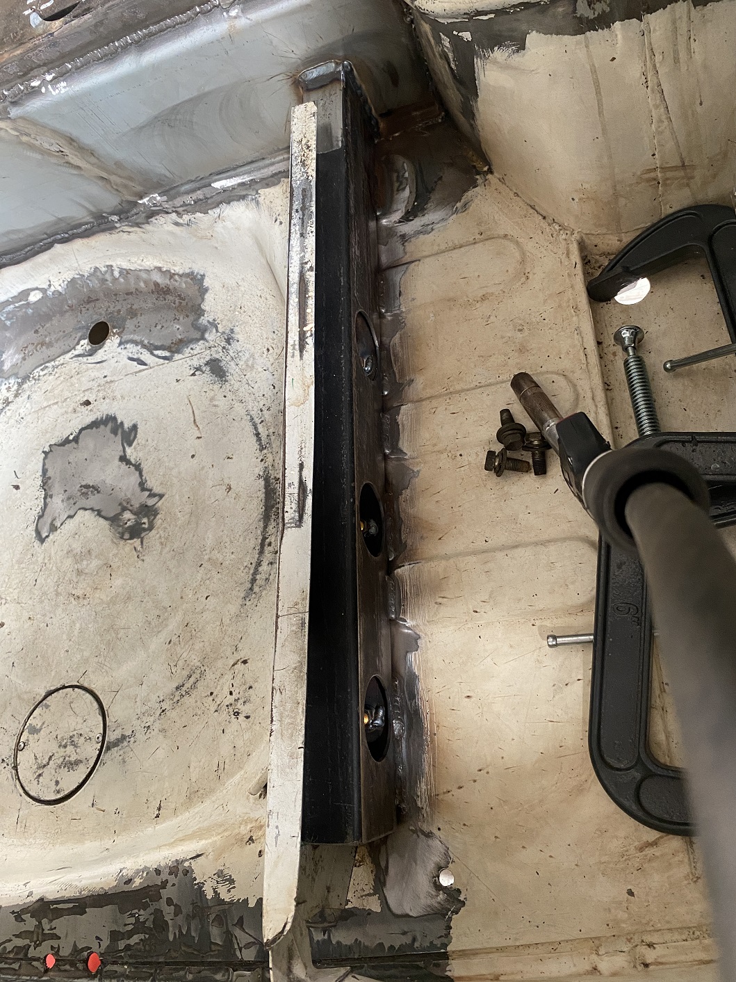
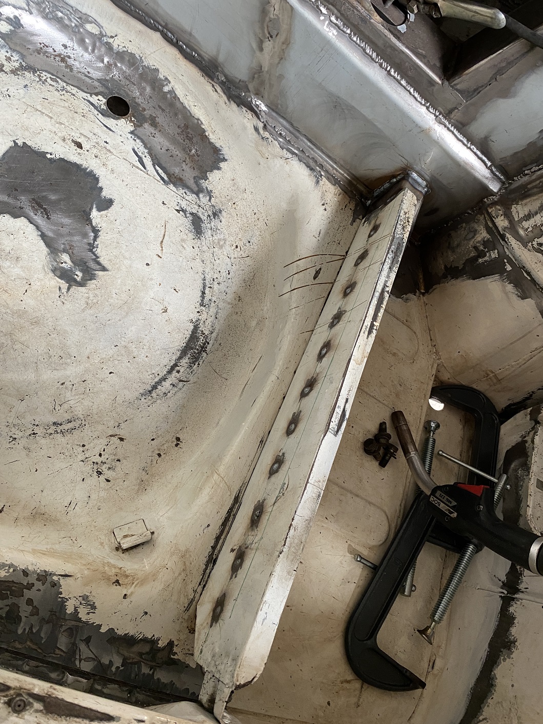
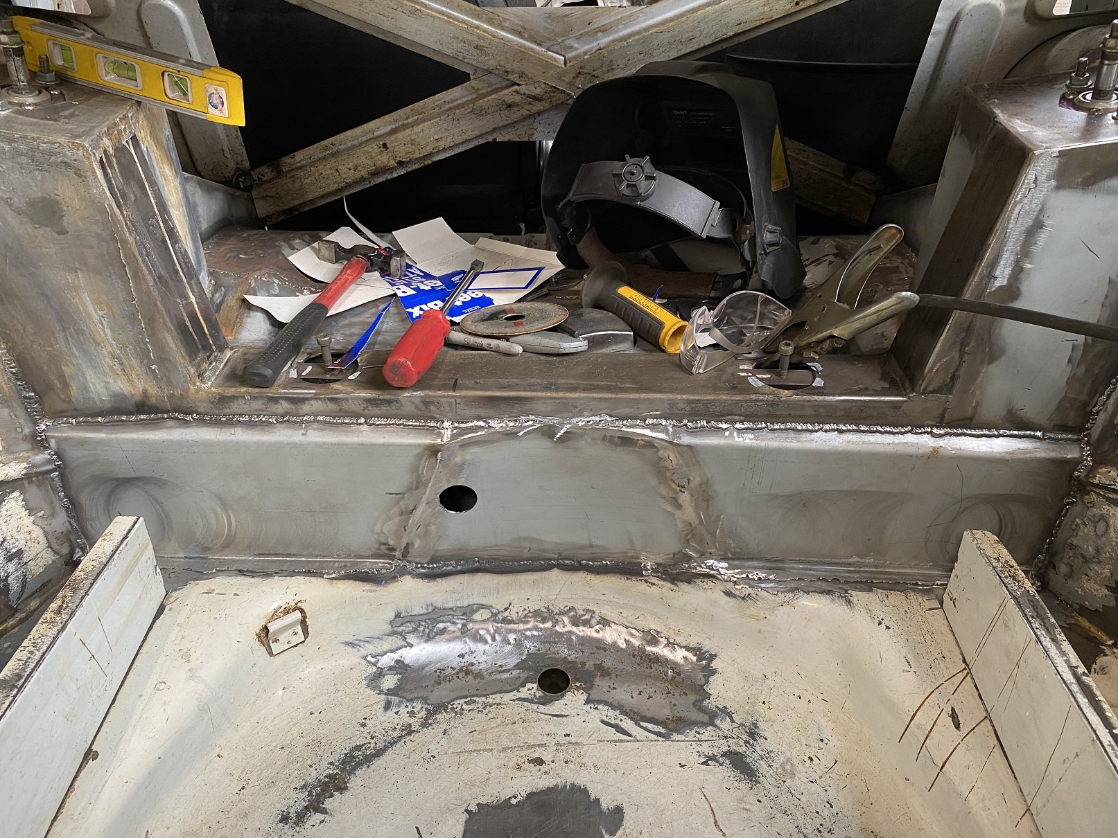
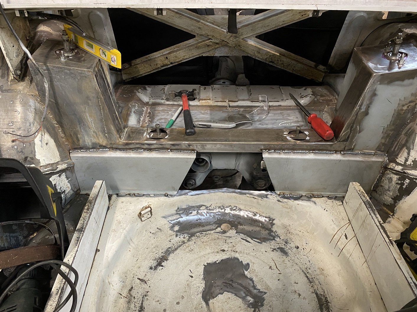
I wanted to have a better tow bar mounting system than the factory one, which relied far to much on the spare wheel well sheet metal. I originally intended to fold up something that would replace the support for the boot floor boards. But I didn't have any suitable sheet metal and it would have been too long and thick to fit in my folder. So I decided that using some rectangular section would be FAR simpler. I made some access holes so I could weld in the captive nuts and if I ever need to replace them, I can get in there with a die grinder. I also notched the bottom with the mill so it fit over the raised sections of floor. Just a couple of spot welds on this side. I'm not sure if I should be worried about bending forces where it's welded on below the strut, it's 1.2mm sheet there, or if I should add some structure in to tie it in with the cross member above it... There is double skinned structure in the rear quarters that wraps around and across the back panel and ties into the bumper mounts, so the back of the car is actually supported. Gives me three M10X1.25 bolt holes. Don't mind the washers, they were just to clamp it for welding. Now I need to do the other side.
-
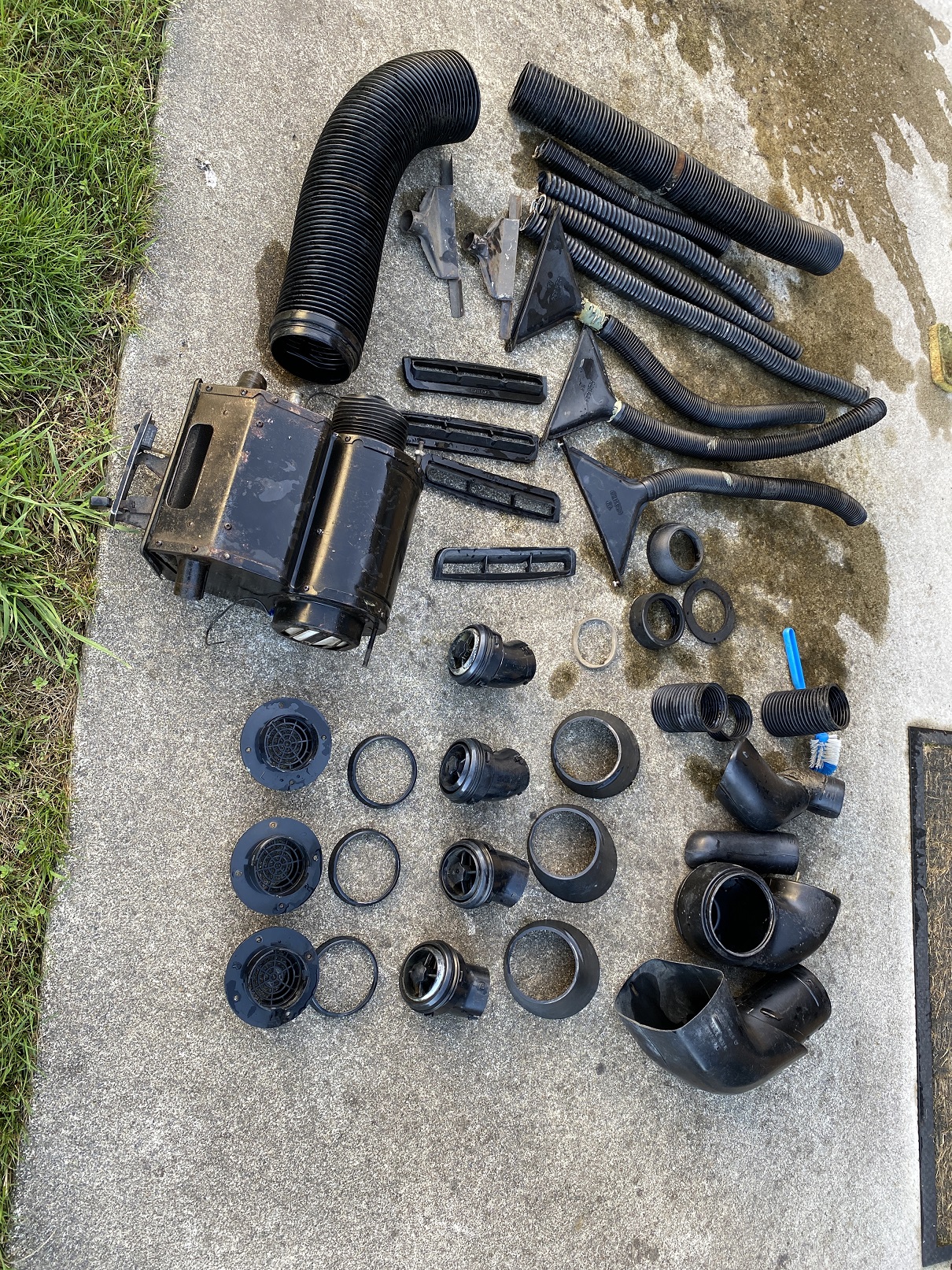
Thanks to @Lord Gruntfuttock my heater system arrived today. I gave the bits a bath in the paddling pool. An outside hot tap is so convenient for this. Looks like I've got almost 2 sets of bits. And a couple of mystery round bits that I suspect may not be from a mini.(left and up from the blue brush) Hopefully the fan works and the heater matrix is not full of holes.
- 52 replies
-
- 15
-
-
Please paint those engine pulleys!
-
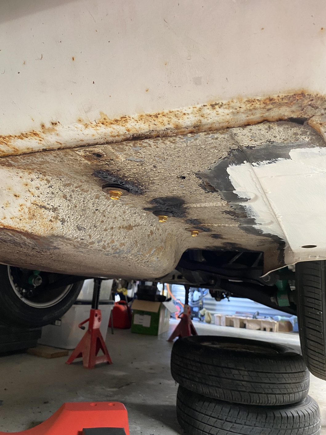
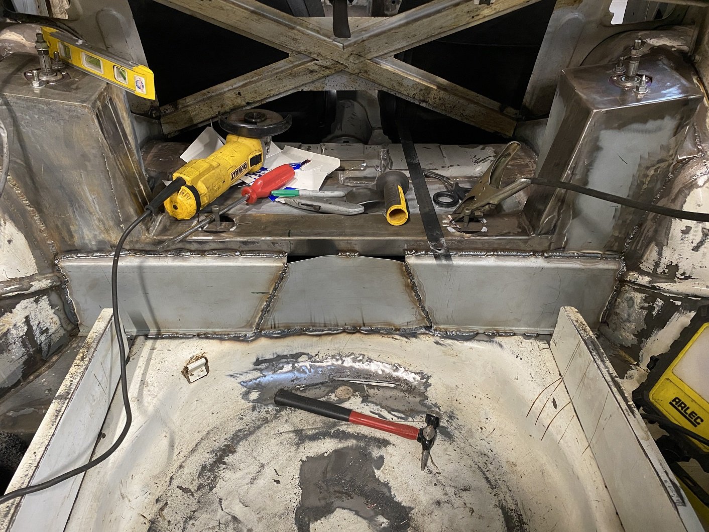
I got all my holes filled. And drilled another orifice so I can tickle the nut on the diff mount.
- 201 replies
-
- 12
-
-
Filling in the hole. 1.2mm is so nice to weld.
- 201 replies
-
- 14
-
-
I have a 2zzge Allex. Goes real good. Lift kicks in at 6400 and starts pulling harder up to 8200 redline. 140 killingwhats apparently. I reckon now must be the best/cheapest time for sourcing these engines. Not uncommon to see at PickAPart now.
-
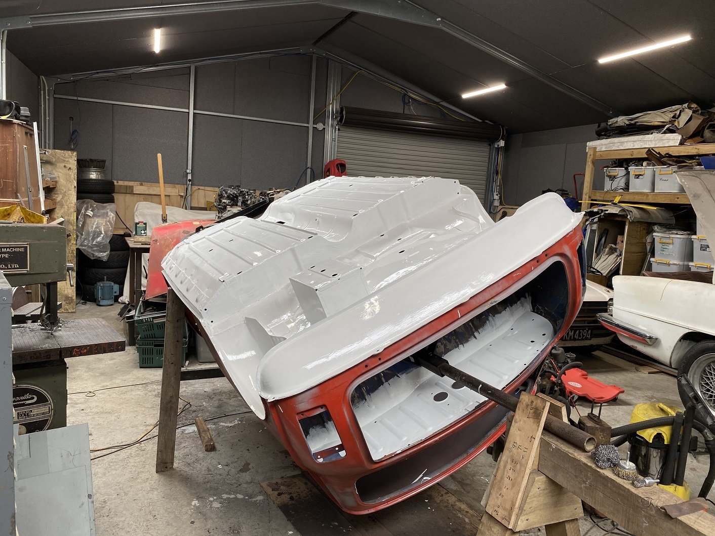
Two coats of epotec brushed on. Needs another coat. I used about 1.2L. I'd probably get better coverage spraying, but I'm not set up to spray yet and I also didn't want to paint everything in the shed white too. I splooged it on heavy around the seams and gaps etc and pushed in the cracks as best I could. Plenty of runs, but it's never really going to be seen. The underside of the parcel tray was a real cunt to get clean enough to paint. It had a lot of surface rust... and rust coloured paint which was covered in old hard glue, that was also brown, which was covered in that fluffy sound deadening. The whole back panel was completely coated in glue and fluffy stuff too. The rotisserie bits in the way, small space and lack of light was an added bonus. I ended up using turps with steel wool and various hand and drill/grinders to get the glue and fluff off. Then I tried using phosphoric acid on the rust and discovered the paint. So had to use paint stripper to get that off. Then I could use the acid and more steel wool and wire brushes. After many hours over days and weeks I decided it was acceptable and I was okay with painting it. Then wax and grease remover.
- 52 replies
-
- 26
-
-
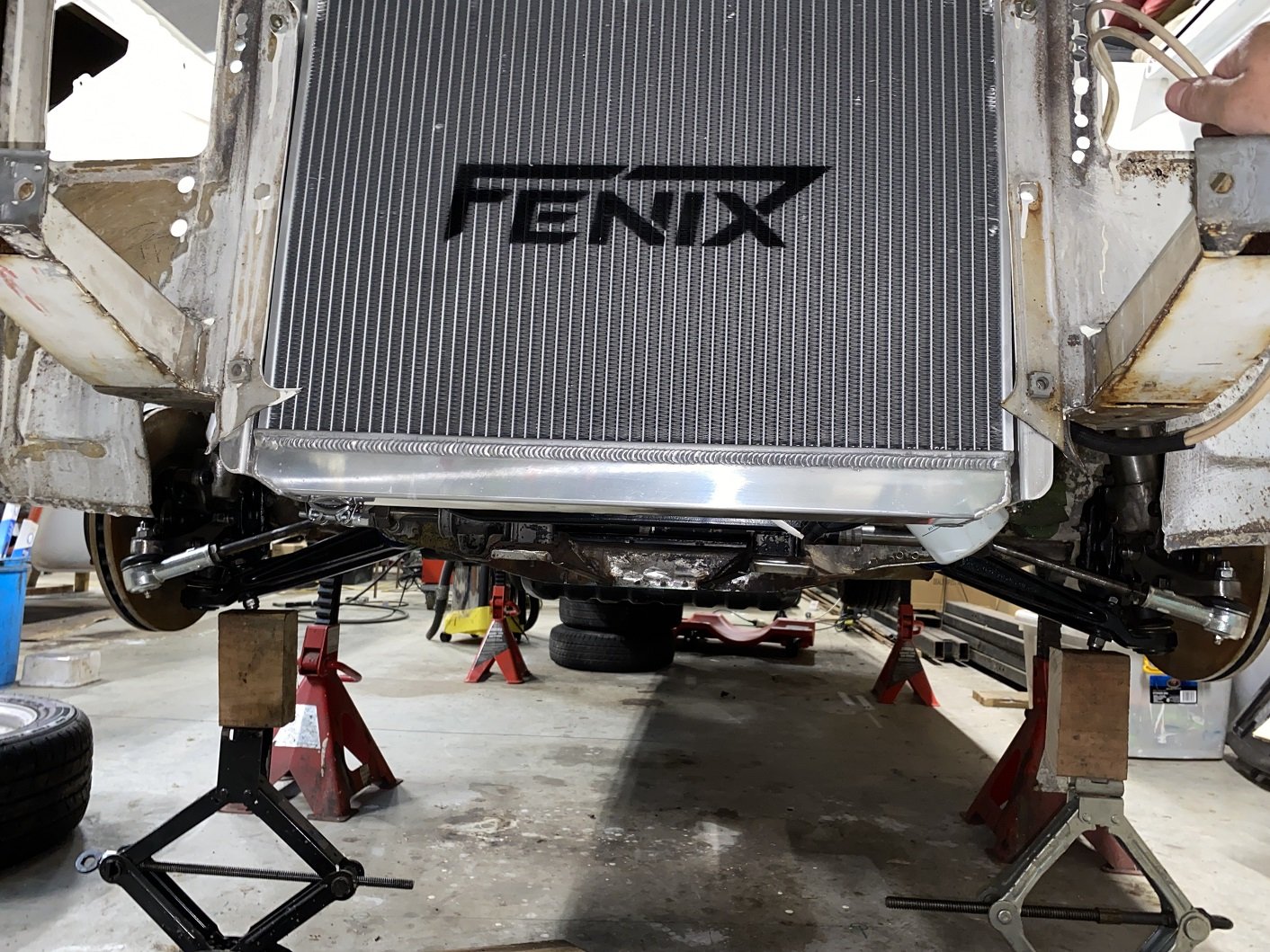
Nice! Thanks for that. I've been busy with the front panel and getting the underside prepped for epoxy primer.