Adoom
-
Posts
2,279 -
Joined
-
Last visited
Everything posted by Adoom
-
I'd just use Epotec 408. But it's a bit of a pain to mix up a tiny batch for small things like this. Any brand names of the aussie stuff? I used some eastwood platinum and thought it was pretty good. But AFAIK it's no longer available in NZ.
-
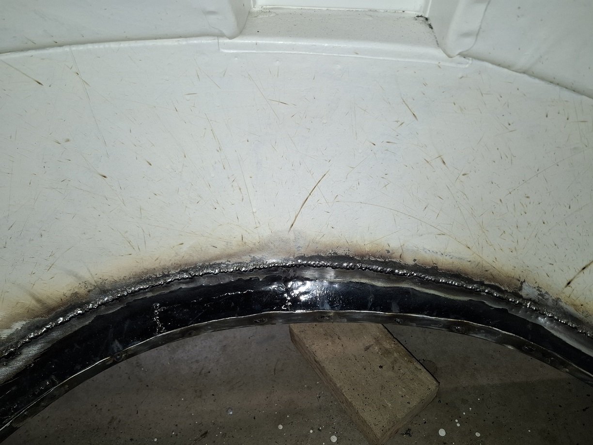
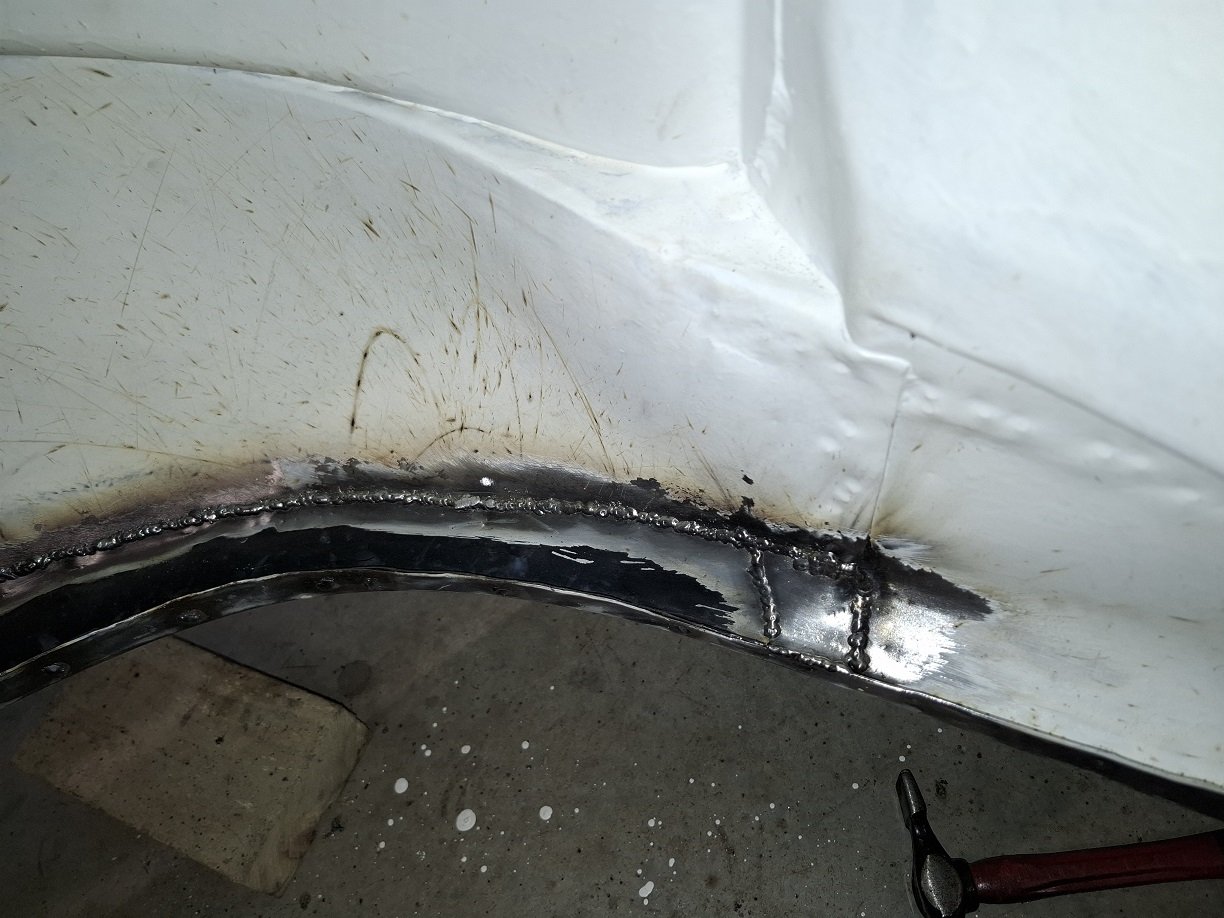
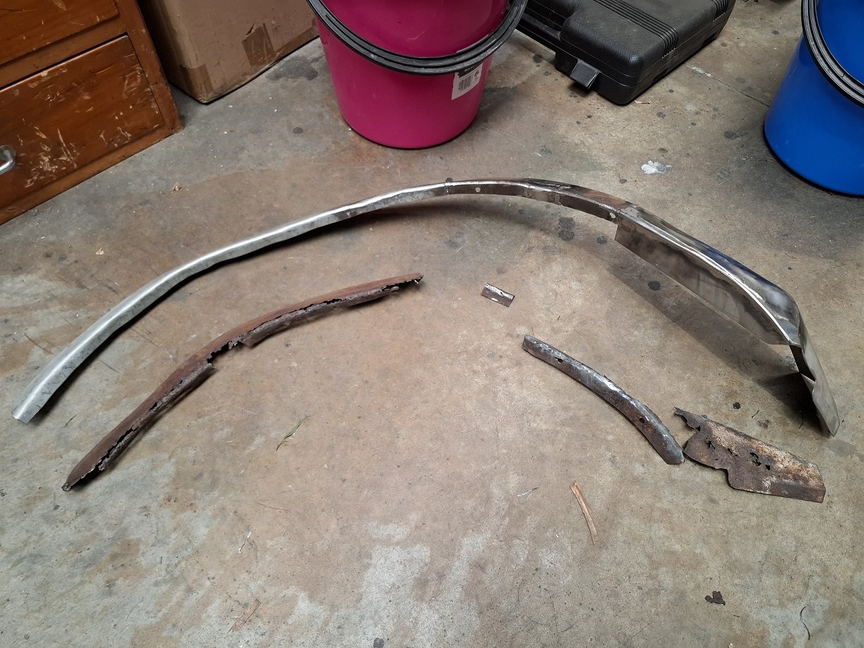
The inner arch. This took ages to get the right shape. See how much frilly I had to replace. Fortunately it's not really visible so I'm not going to grind the welds down. POR15 really is shit on new steel and the surface has no 'tooth', just peels off.

- 201 replies
-
- 12
-

-

-

Random slightly cool stuff you built but not worth its own thread, thread
Adoom replied to h4nd's topic in Other Projects
I got some last year. From an OS recommendation, possibly from you. Should have got a larger size. Found the drawstrings didn't like to stay tied and some fell off. -
Random slightly cool stuff you built but not worth its own thread, thread
Adoom replied to h4nd's topic in Other Projects
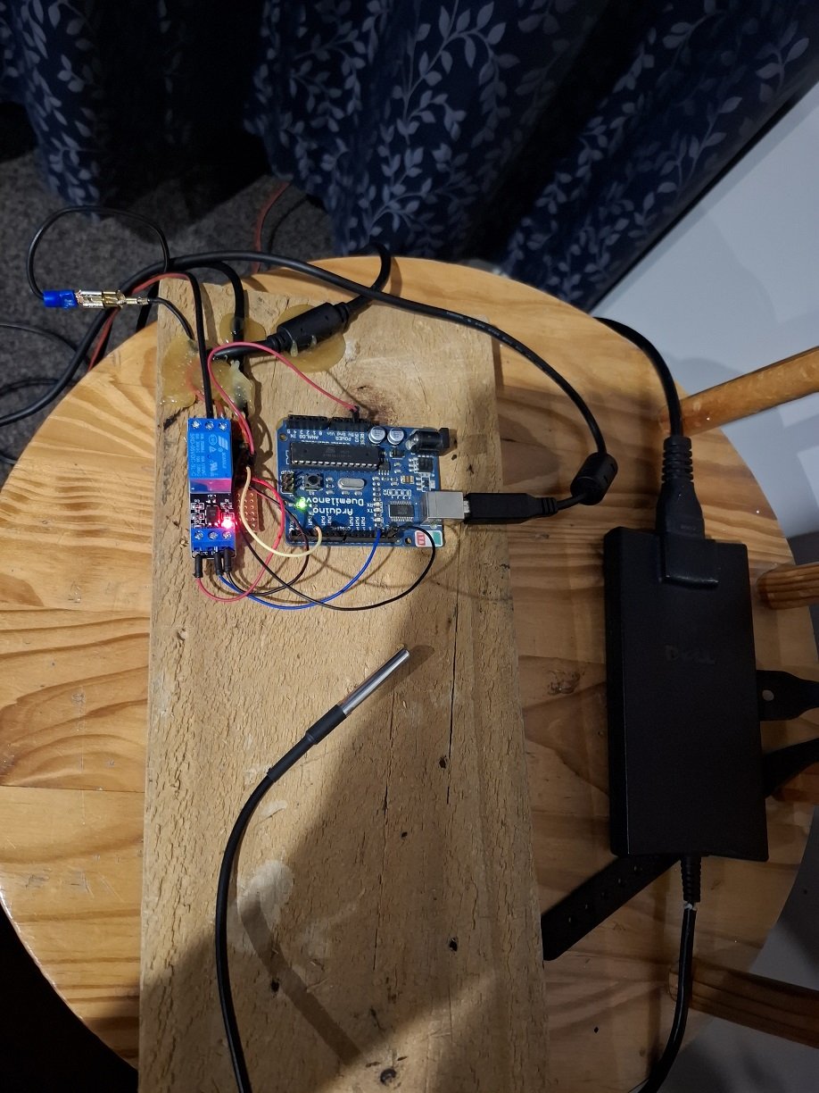
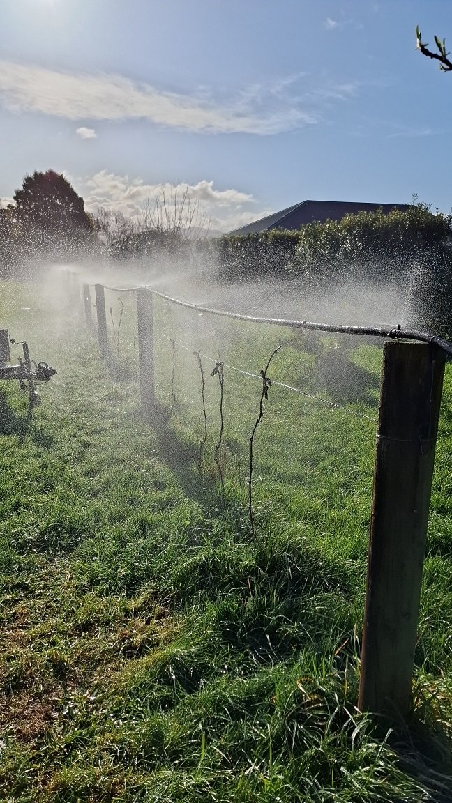
So the new shoots of my grape vines keep getting fucked by late frosts. I had no luck at all using frost cloth. It's also super tedious to put on cause I've got 40m of grape.... erm fence. So this spring I made a thing. Frost doesn't like water cause it's warmer than ice so I put sprinklers over them. I put some extra sprayers at low spots to drain the pipe when it's off. I don't want the water freezing in there making it useless. But I'm not gonna manually turn that shit on early in the morning. So I dug up an old arduino board. And bought a relay thingy and a waterproof temp sensor and a 24 volt solenoid valve thingy(not pictured) for the outside tap. And hot glue. Lots of hot glue so stuff stays plugged in. Old laptop power brick is perfect for the solenoid valve. My sketch checks the temperature every 10 seconds. If it drops below 0.5 degrees it turns on the water for 60 seconds. Then turns it off and waits 5 minutes before looping back to checking the temperature again. I had some 'stunt frost' for testing. The brass solenoid valve is screwed directly to the outside tap which is attached to the brick facade of the house. It's pretty loud when it thumps on, I think it might be loud enough to wake me up. Hopefully I'll get some grapes this year, if the birds don't steal them all.
-
You'd need to go through design approval because changing the lengths of the arms can mess with the geometry. You will need to accurately draw, with measurements, the modified suspension. There is a specific form for custom/modified IRS. It's in the documents section of the LVVTA website. On my Triumph(they are quite narrow), I narrowed a nissan IRS, so the arms and geometry were original, the inner pickups were just closer together. No design approval required. Your cert man just needs to be happy it's constructed "in a workman like manner". It was still a lot of work/measuring/thinking to get the subframe aligned and make new body mounts. And make new diff mounts. In both cases you will need custom length drive shafts made. It'd be WAAAY less fuck around to just use different offset wheels. Possibly cost less than the custom driveshafts alone. EDIT: Not sure if you mean, "make new arms", or "move existing arms inboard". I had assumed the first one.
-
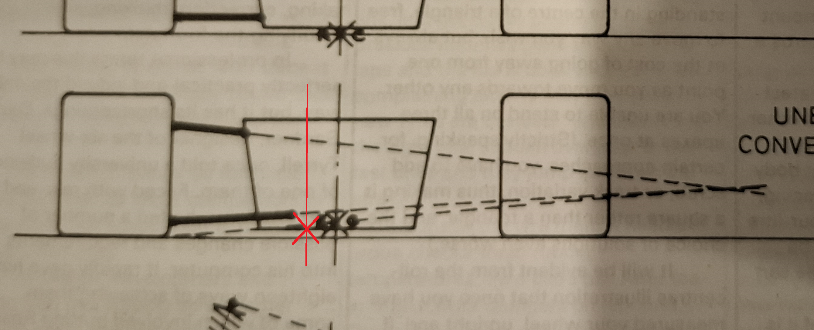
I hadn't actually thought of that. Referring to one of Allan Staniforth's books, moving the inner pickup points closer together would lower the roll center slightly. That's good, I think. I don't think it would do much else, or at least anything I'd notice.
-
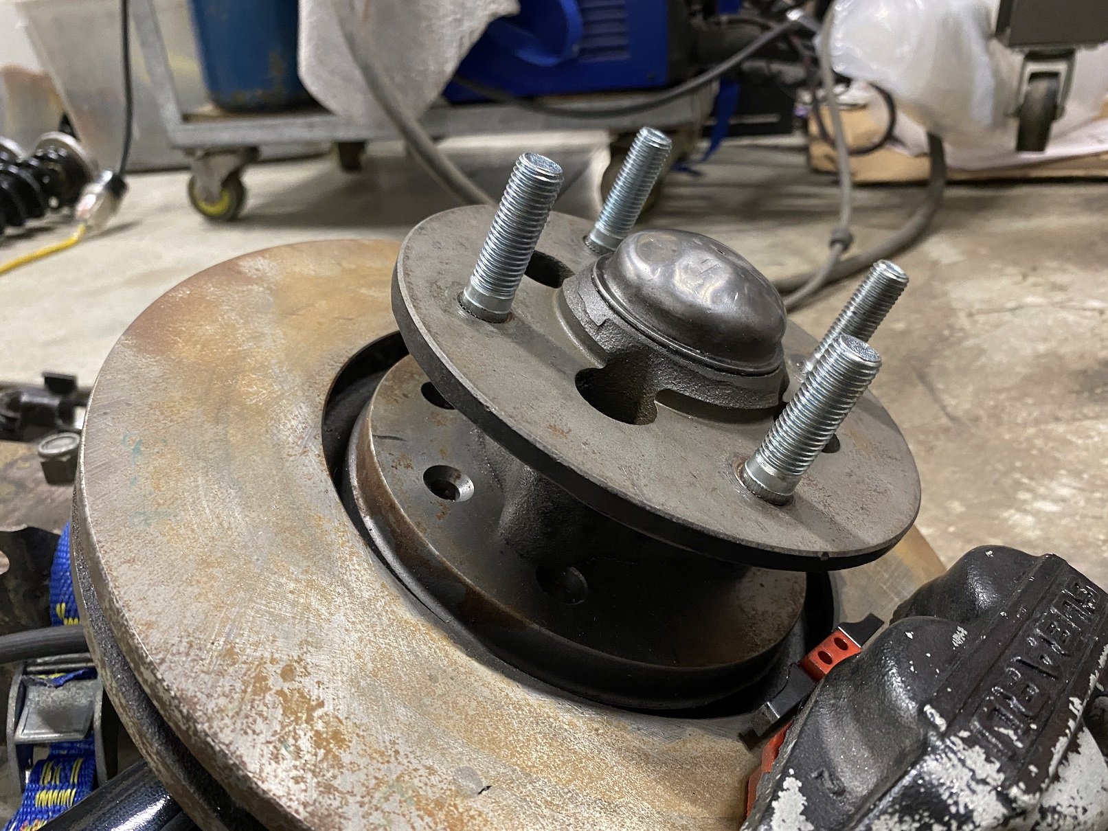
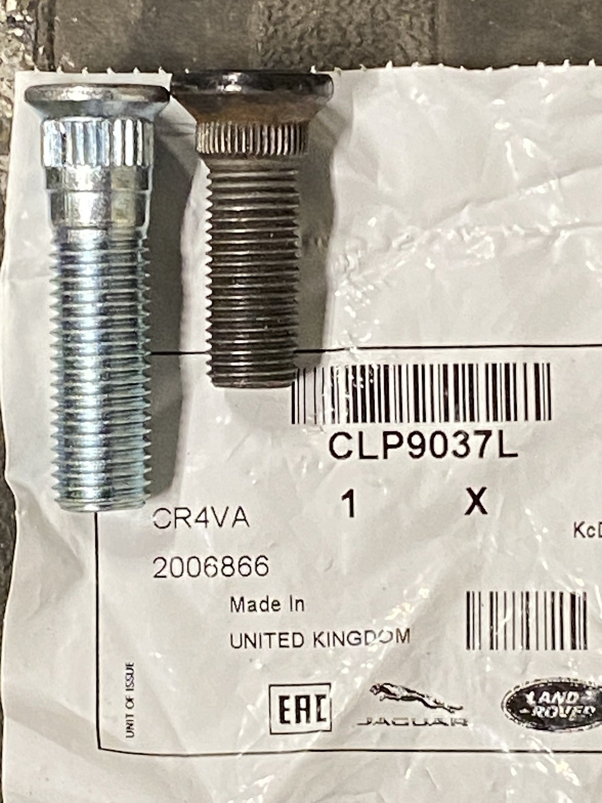
Just in case someone else needs longer front wheel studs for a 2500 because they have gone from alloys that use shank nuts to alloys that use taper nuts and there is not enough thread engagement. And they also want to go metric because they installed nissan rear suspension. These are the only solution I found. Fuck all wheel studs have a tapered head like that. They are from a Landrover Freelander. I got them from Rimmer Bros in the UK. The OD of the knurl is the same as the originals but as you can see from the photo it's a coarser knurl. They are M12X1.5, a little bigger than the 7/16th original ones. I'll have to change the nissan studs too because they are M12X1.25. They pulled into the hub fine using a spacer, a washer, a shank nut and the impact gun. They are TIGHT.
- 201 replies
-
- 21
-
-
Epotec 408 epoxy. 2-3 coats. I did most of it with a brush. Took fucking ages, over 4 days. Near the end I remembered I had some small fluffy rollers and discovered they were much faster and also got in little divots that the brush just skipped over.
- 201 replies
-
- 33
-
-
I should update this. Did I forget I made this thread? Hopefully I have more photos. It's not really a resto. More of a cleaning because it was just packed with grease and gunge. It's supposed to be about 1200kg. Do you also have one? The gearing for the knee seems REALLY tight, up or down. It's a two handed job just to turn the small hand wheel. It's like the gears are meshed too closely, but there's no adjustment. I'm planning on making a flip out handle so I have more leverage. The later and bigger ones have a long handle rather than a small wheel as far as I know.
-
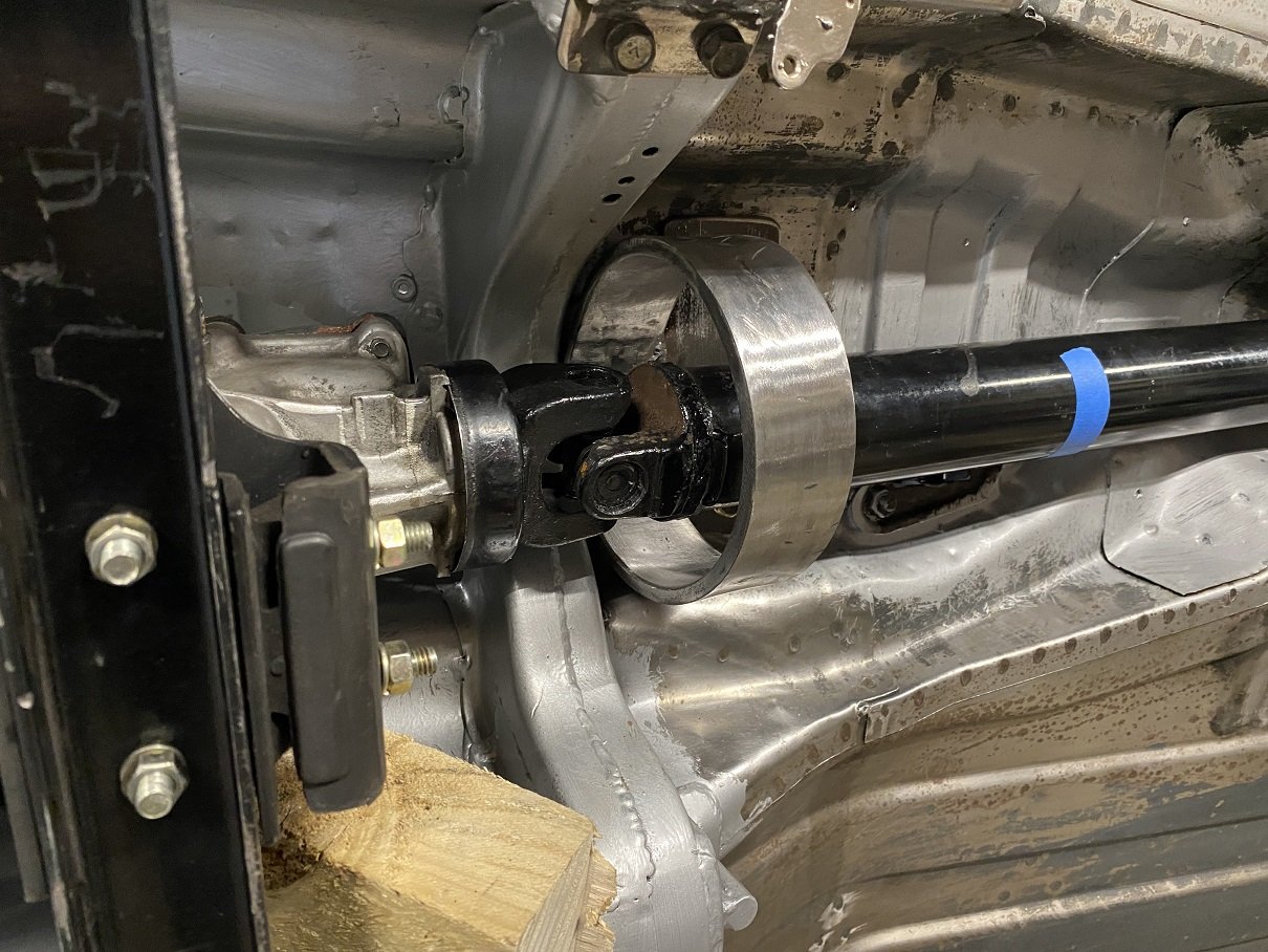
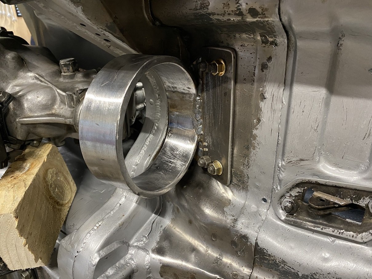
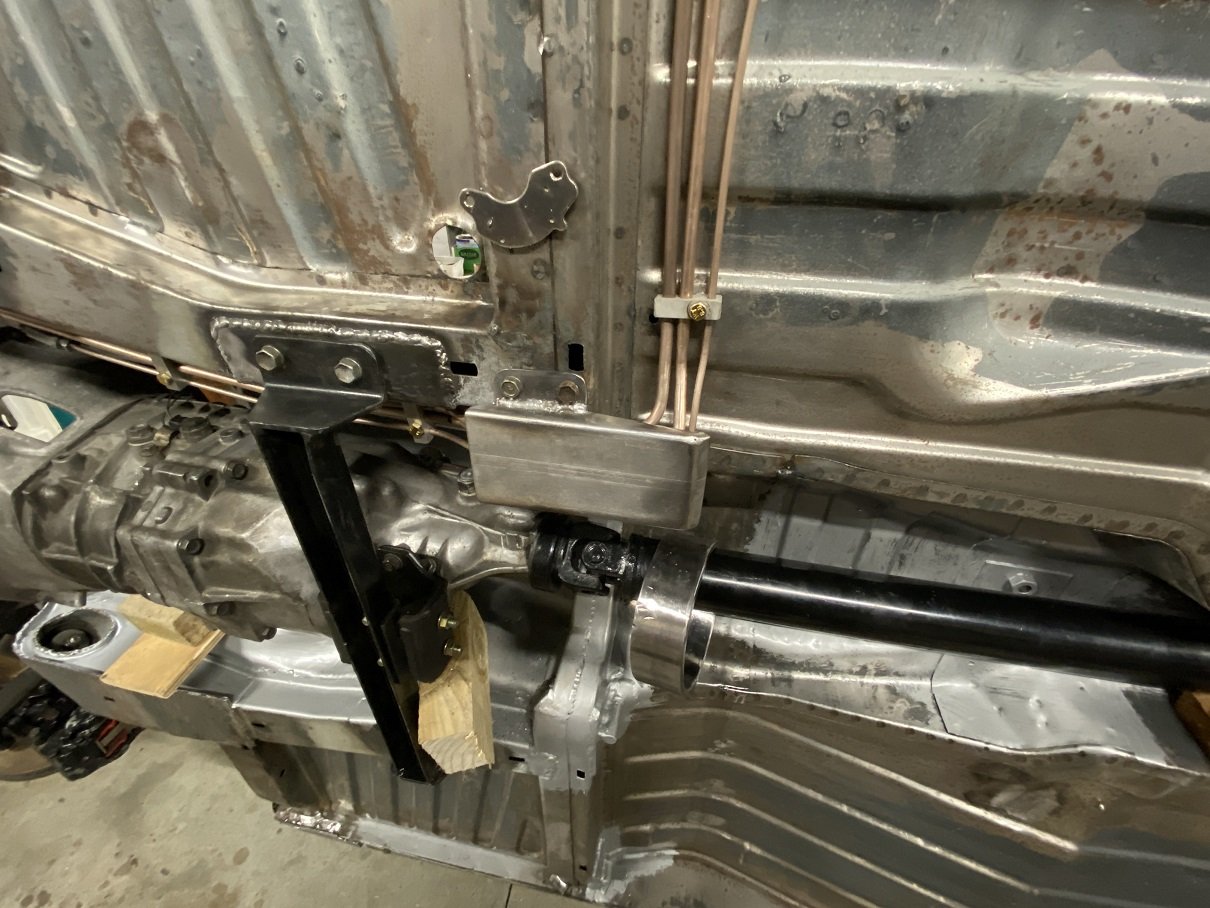
Driveshaft hoop! The ring is 8X50mm. The spreader plates are each 80X60X3mm. The bolts are M10. The bracket off the ring is 160X60X5mm. AFAIK that fits with the specs.
- 201 replies
-
- 21
-
-
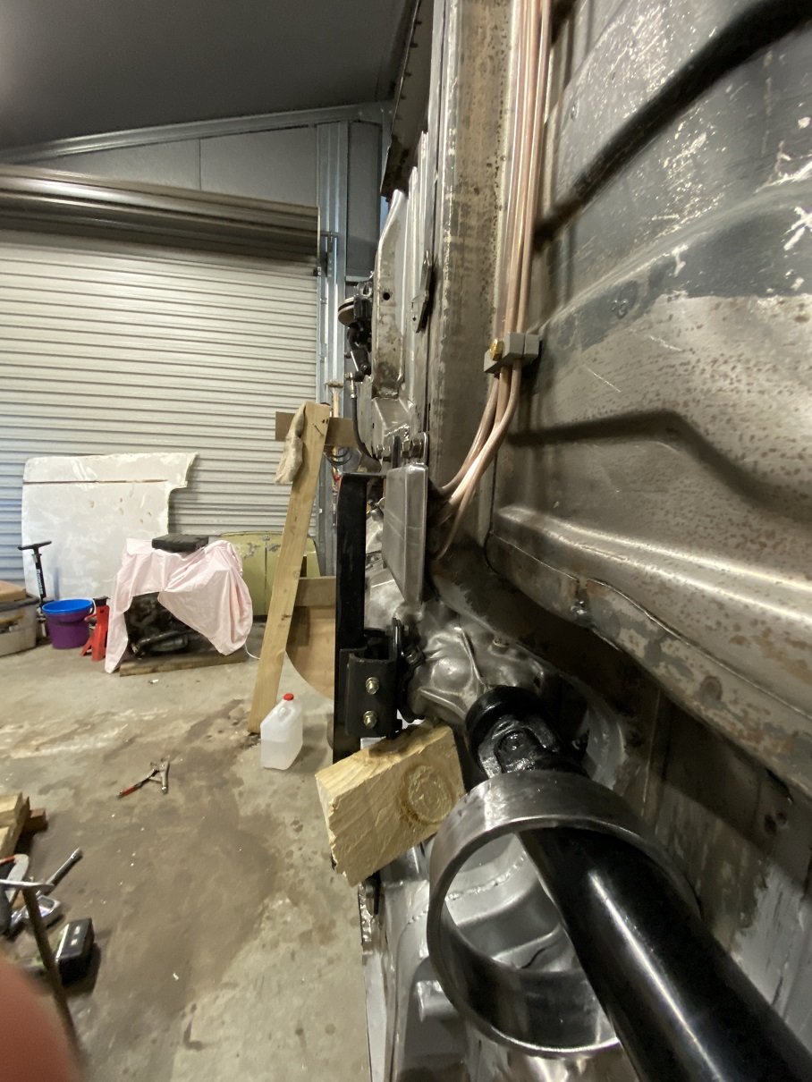
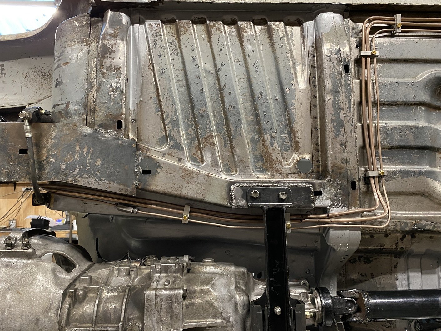
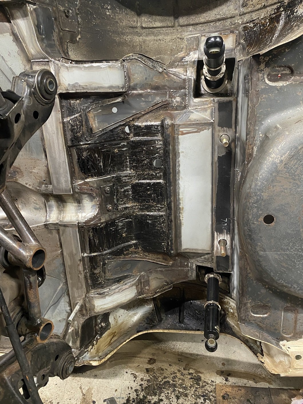
I then made the cover for the hardlines. Might be overkill, it's pretty sturdy. Still thinking how I want to mount the driveshaft hoop. Can't really bolt through the floor there because there is a cavity. I'm thinking I'll make some strut things that go forward to the box section dealie, maybe won't make it removable.
- 201 replies
-
- 10
-
-
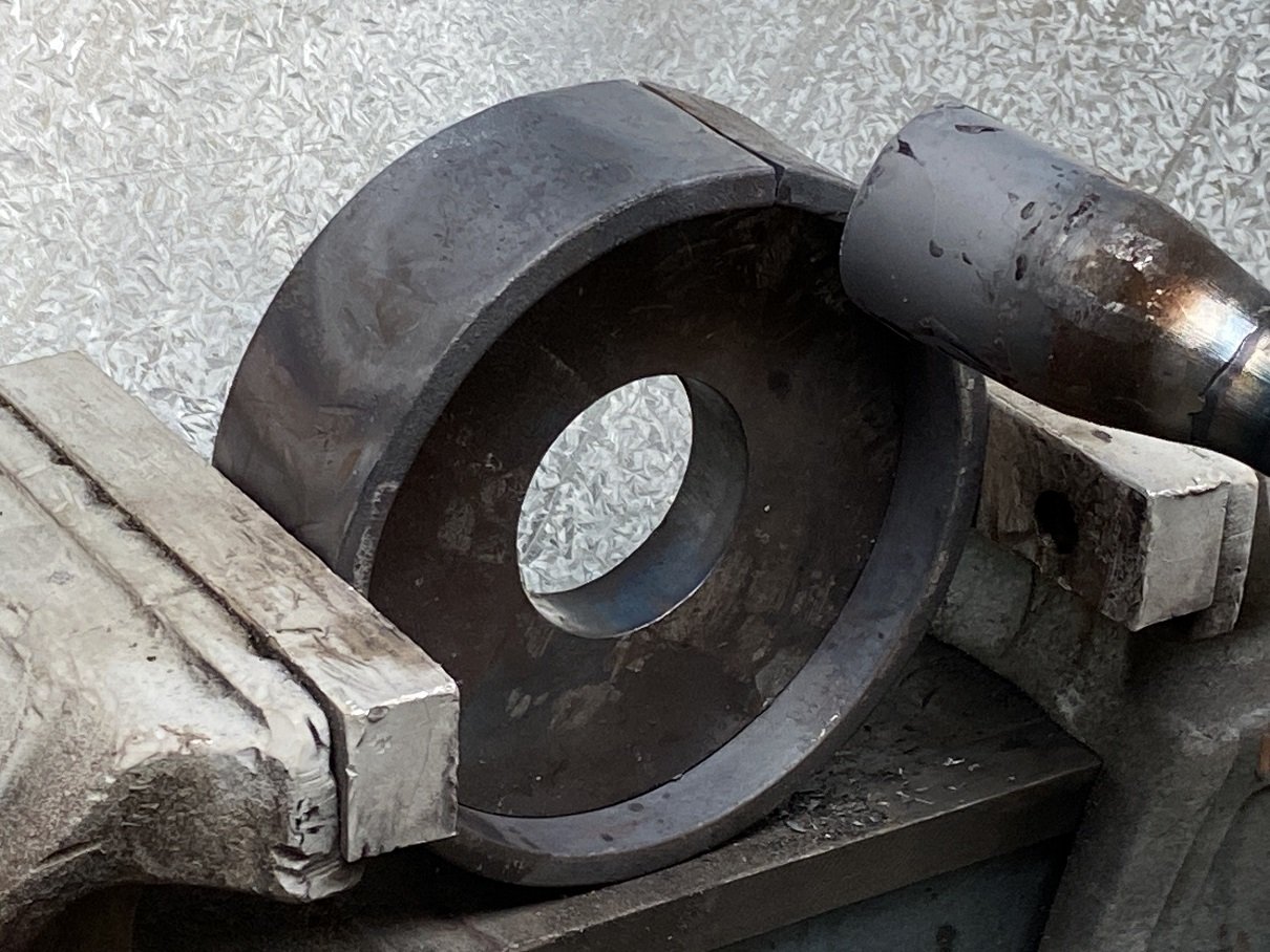
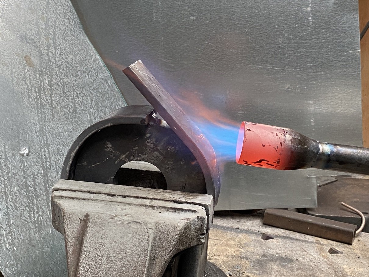
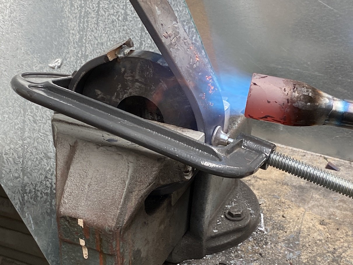
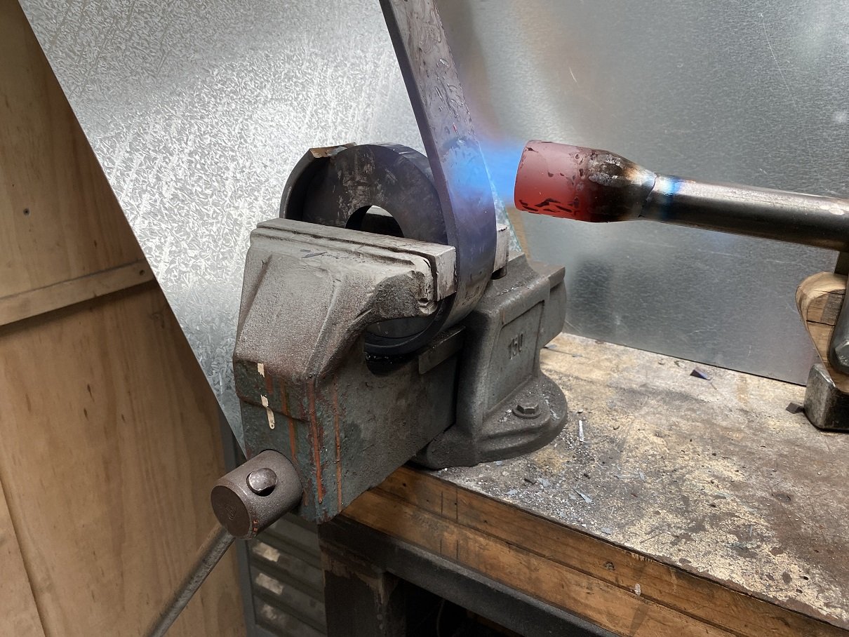
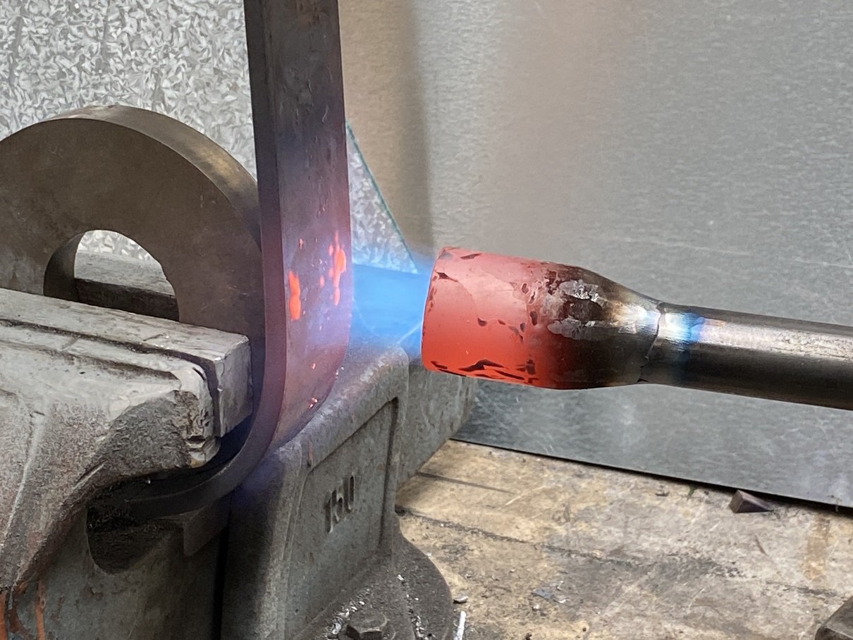
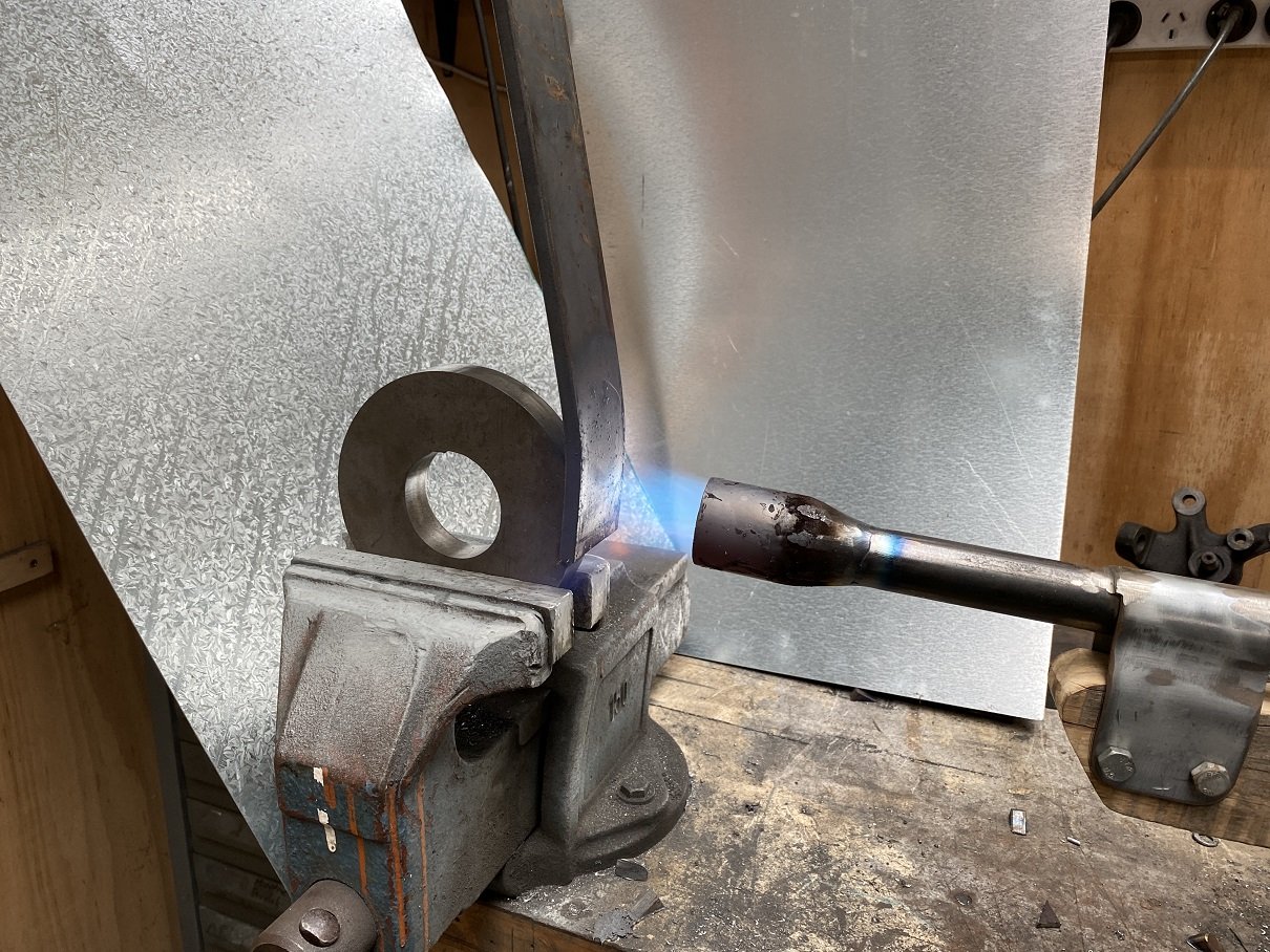
I need to make the driveshaft safety loop. I've got no 5mm flat bar, but I do have a whole lot of 8mm... But how will I make it round?! I'd need a press or something. ...WAIT! THE WEED WAND makes fire! And I have this convenient round thing. After a while the zinc on the 'heat shield' starts to melt... NICE! Only took an hour. Here's what it sounds like. I added a clickbait title so I can go viral.
- 201 replies
-
- 17
-
-
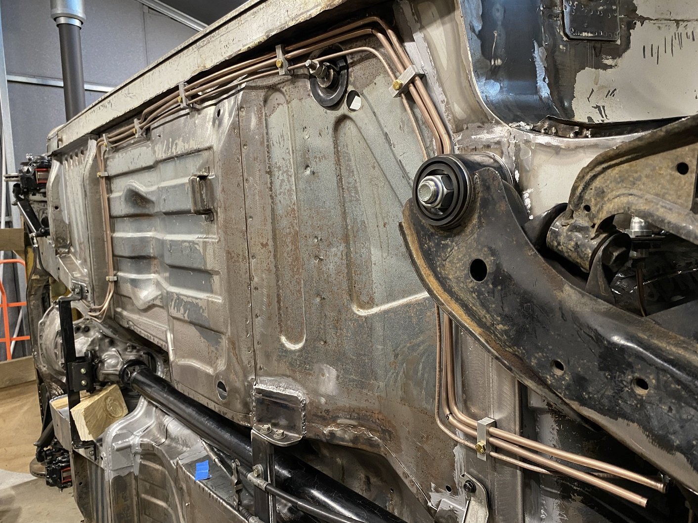
Took hours and hours to mill all those little clamps. Most of the time was spent on setting up for each one. I'm not winning any awards for neatest brake and fuel lines. I'll make a bolt on cover to hide the mess.... 'protect'.... the lines where they cross over the chassis rail. The gearbox cross member offers some protection already because it's about 40mm lower.
- 201 replies
-
- 17
-
-
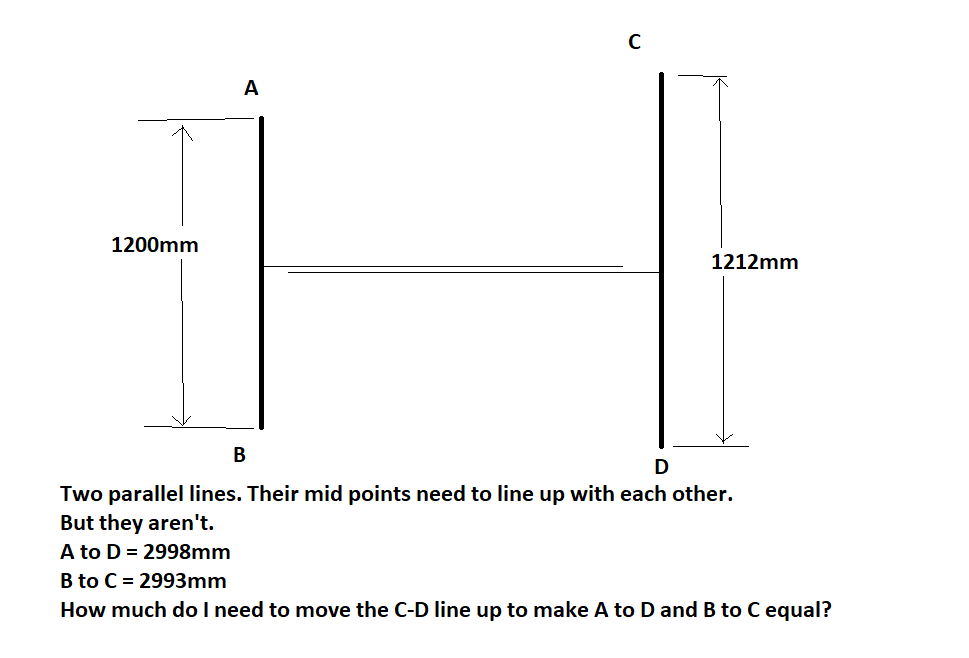
This has me stumped. Can someone stick it in CAD and get the answer easy as? This is the measurements between the front and rear balljoints... trying to make sure the rear is straight.
-
Aren't they just the cutest little wheels. So glad my fancy brakes fit. with half a gnat's foreskin to spare. I'm fairly sure they are 'straya contessa "minilites". 10" X 5"
- 52 replies
-
- 23
-
-
Local cert man, Julian, said much the same. "as long as it doesn't rub".
-
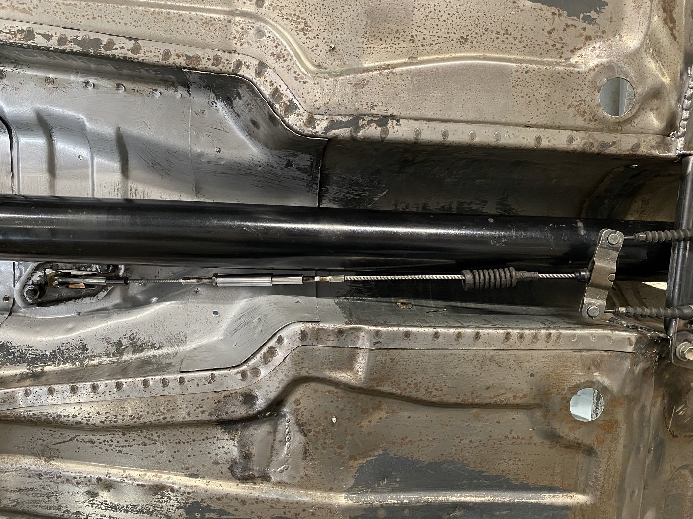
Or, I could get Melbar cables to make me a new cable that is adjusted at one end or the other, so it's only the cable that is close to the propshaft, not the adjuster?
-
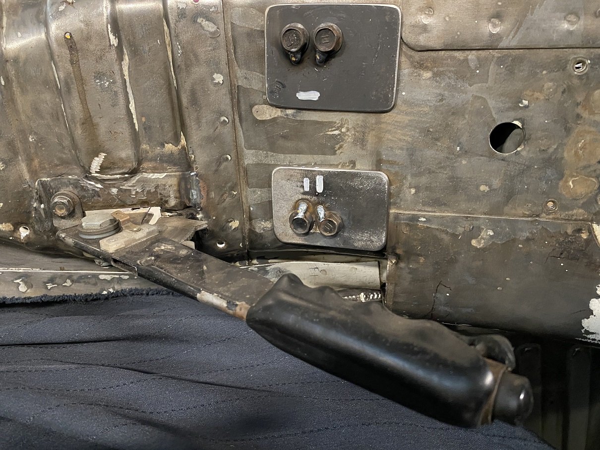
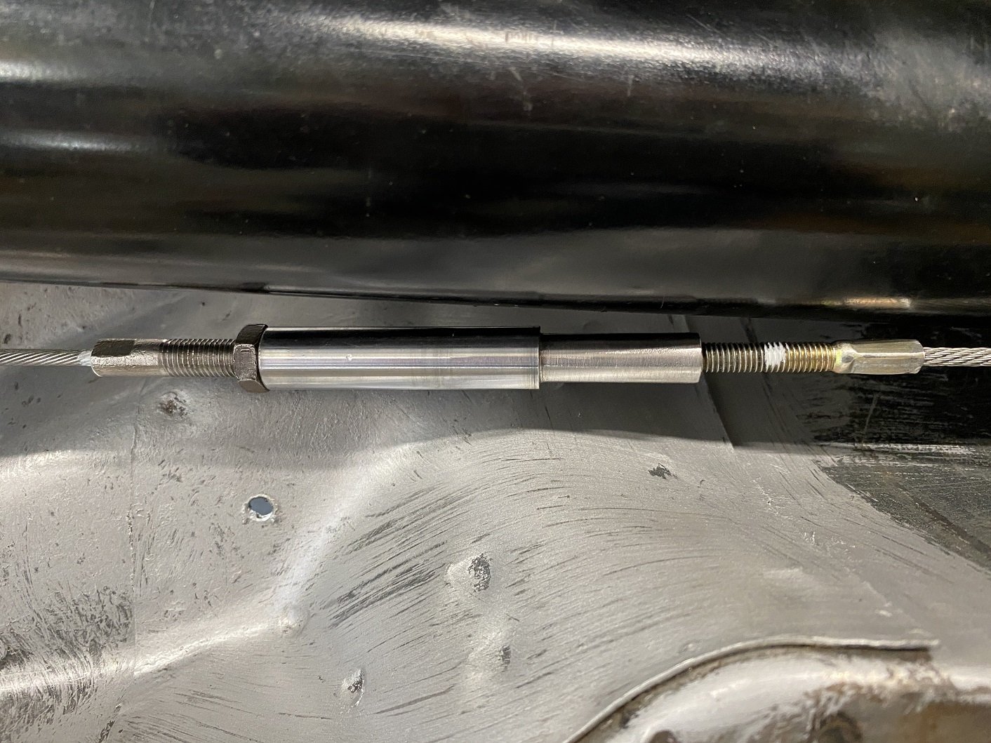
How close is too close? There is about 5mm. This is with the handbrake engaged. The left side is Triumph, so 5/16th thread. I've shortened that. The right side is Toyota, M6 thread and unmodified. The bracket on the right could move over about 10mm before the balance bar thing hits the tunnel. But it makes only a couple mm difference to the size of the gap. I suppose I could do a project Binky and make a shorter balance bar that lets me move it farther. I can probably move the handbrake over a tiny bit.
-
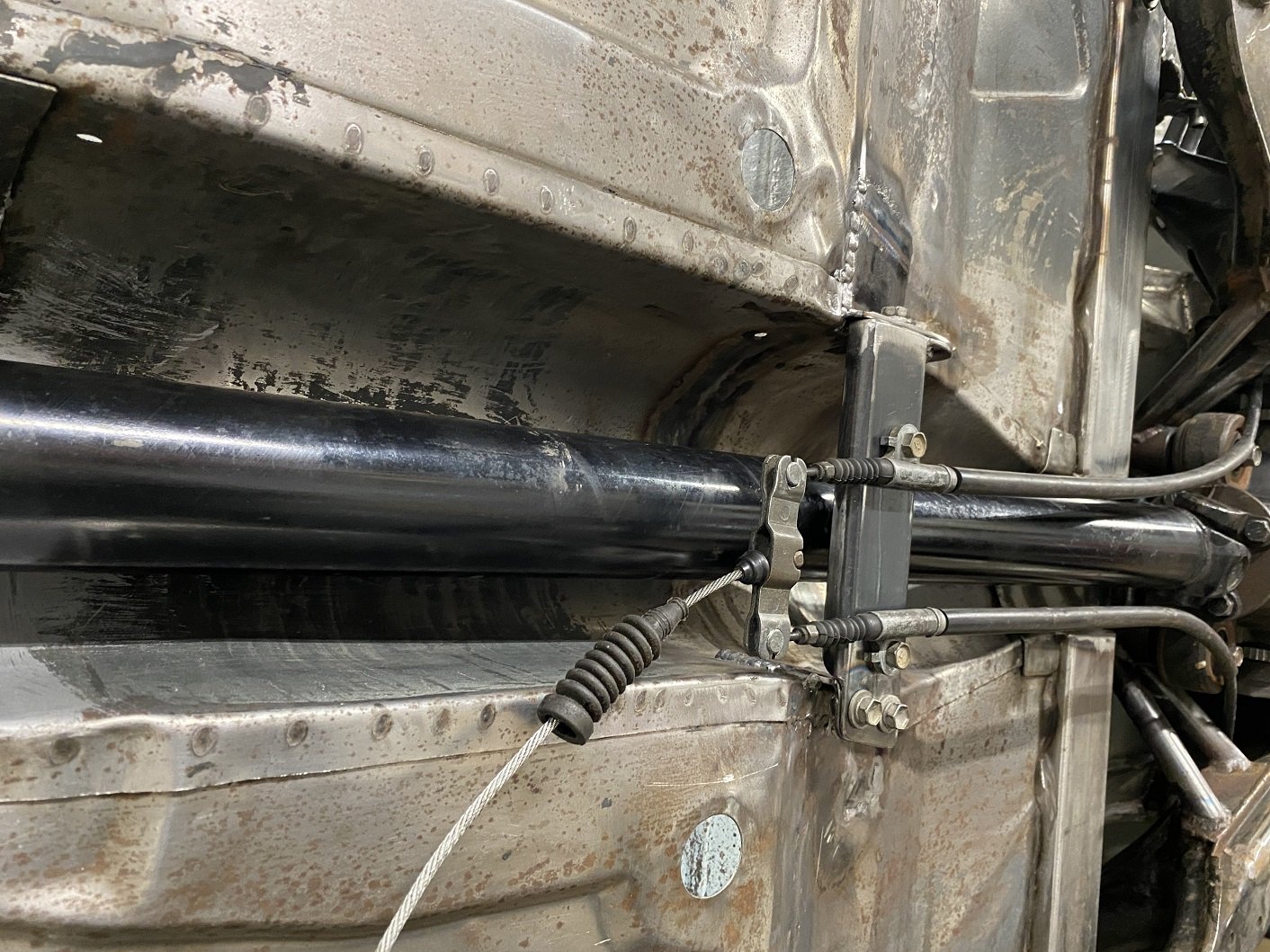
I made the handbrake cable bracket. I can make the cable outer touch the propshaft flange, so I'll make some brackets to hold them away. I'm fairly confident they wouldn't touch by themselves anyway... I must decide how I want to marry the Triumph handbrake lever to the toyota cable so it's still adjustable. The handbrake is offset to the drivers side, so the cable 'just' misses the propshaft.
- 201 replies
-
- 13
-
-
Fuck, I must have spent at least 4 hours grinding the remains of those spring mounts off. There were so many spot welds, I basically has to turn 90% of it into dust on the floor.
-
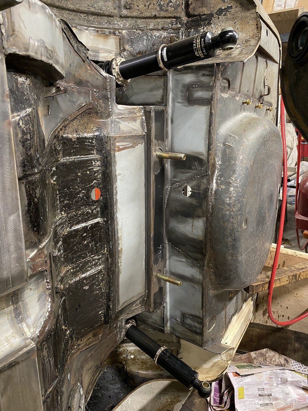
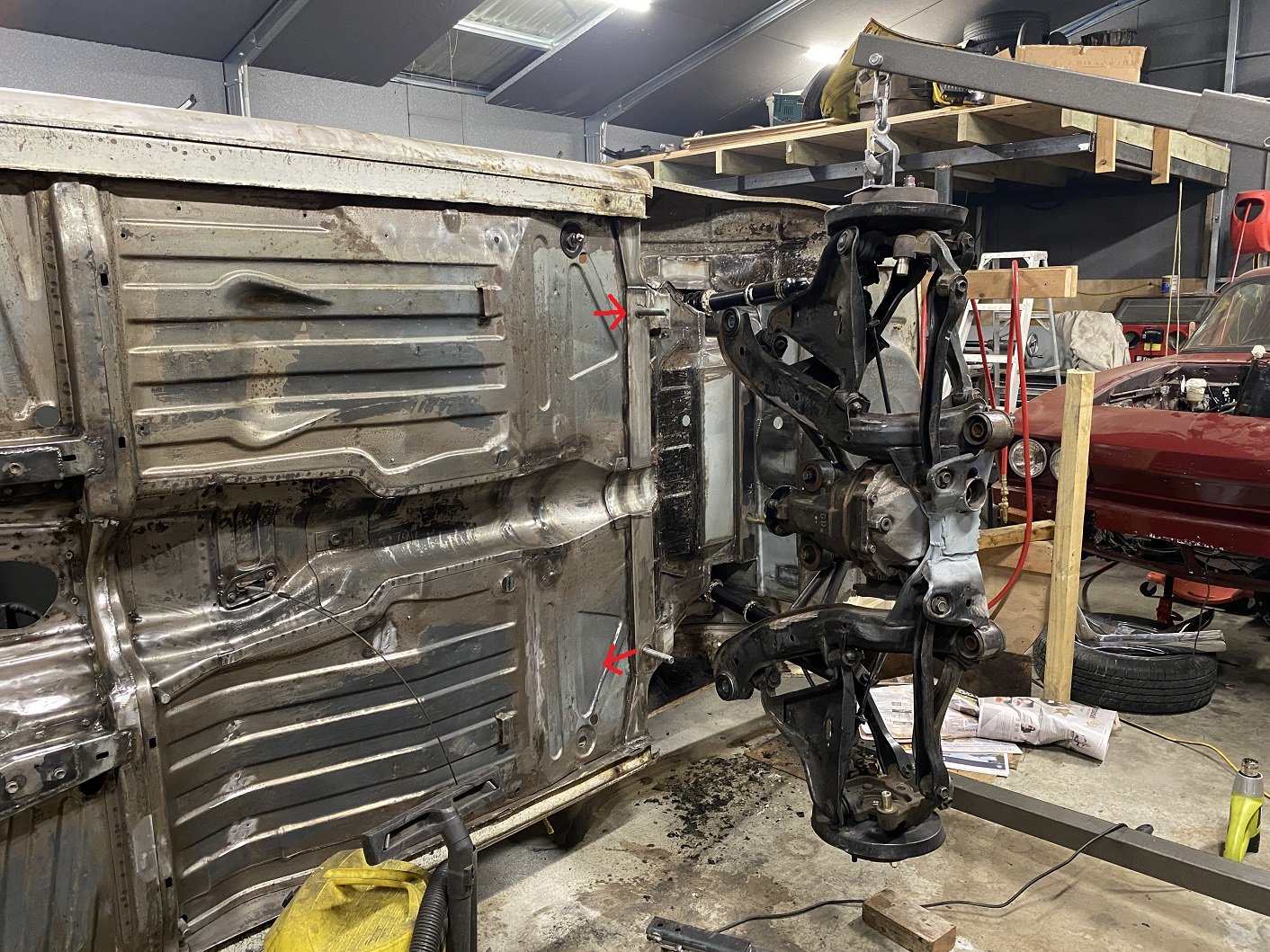
I lifted the rear subframe off. Feels like one of those photos showing off the big fish I caught... With the car like this it made it really easy to measure between the front and rear lower ball joints to find the wheelbase on the drivers side was longer than the passenger side. I suspect it's because I built the alignment jig for the two front mounts on the yellow car, not this one. I had oversized the holes that the studs come through to allow some wiggle room, but I need to take a further 4mm off both sides. Once I can get it on a wheel alignment machine to make sure it's straight the studs will get welded in solid. I've started cleaning off the last of the underseal. I've got to also remove the remains of the original spring seat reinforcement.
- 201 replies
-
- 19
-
-
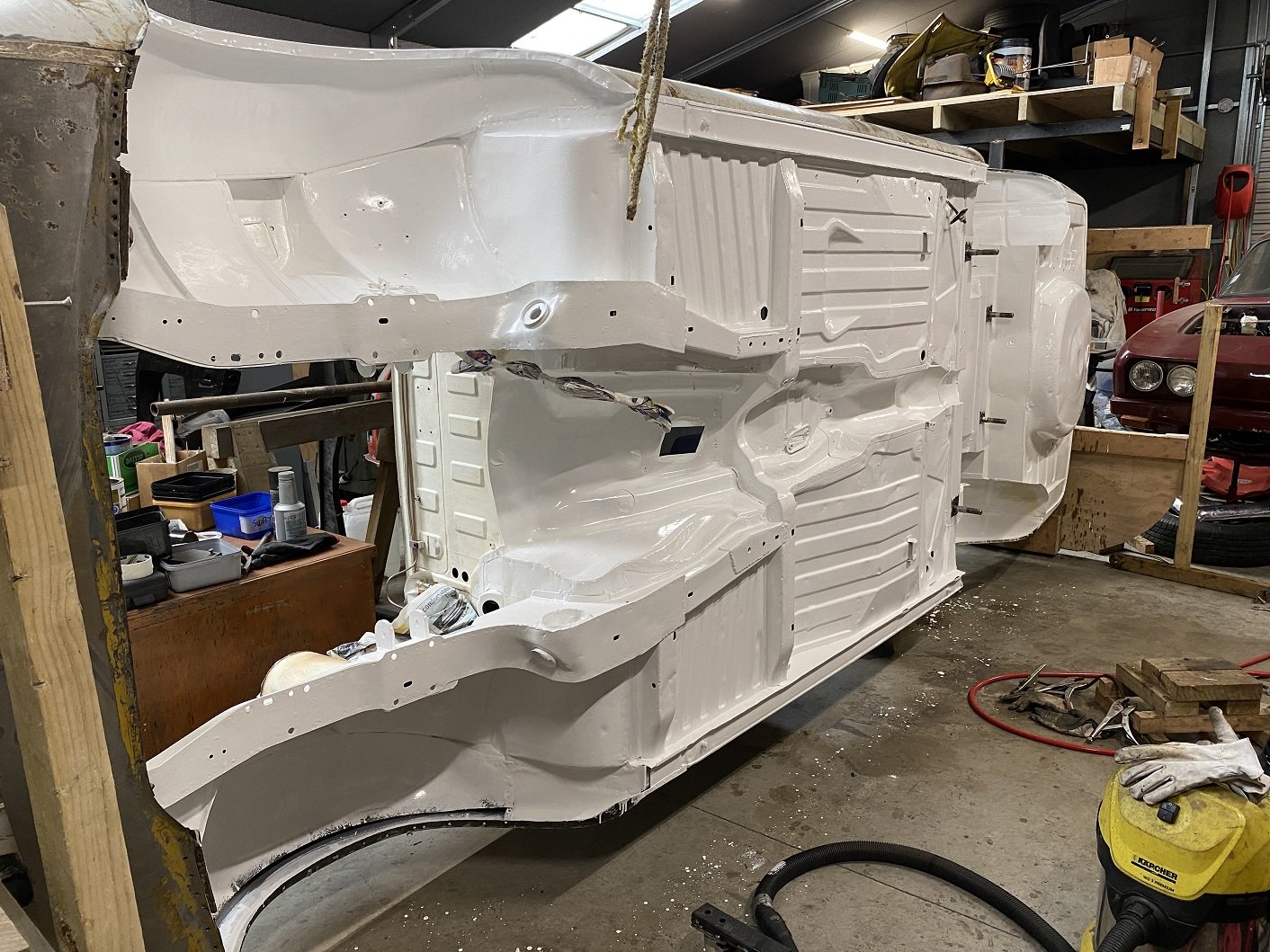
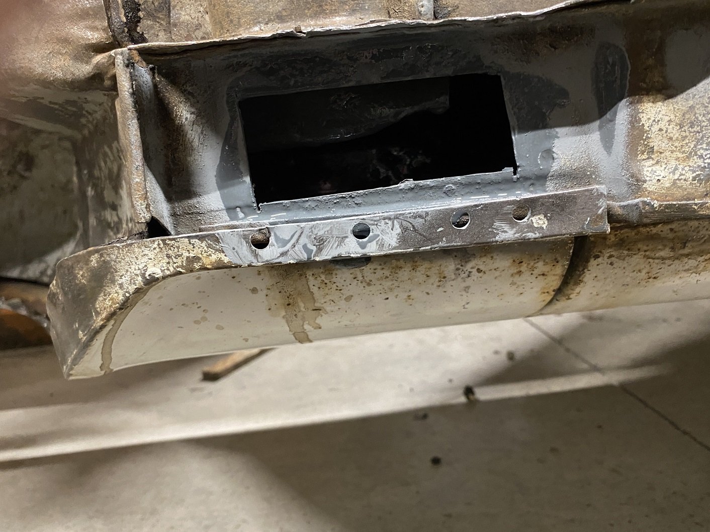
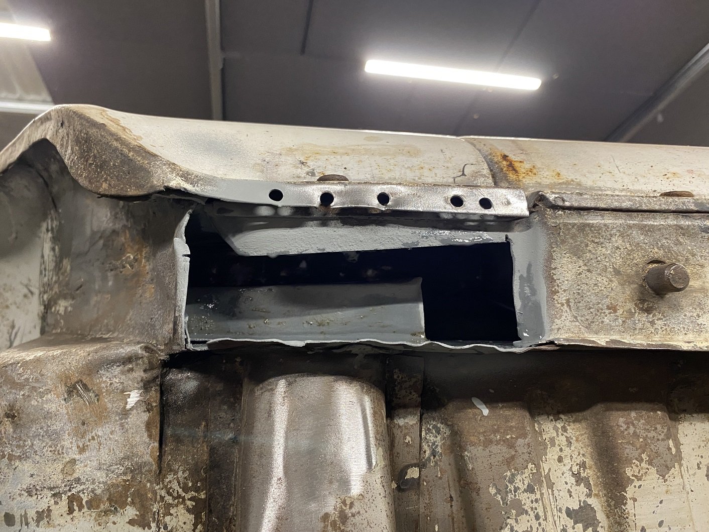
While I've got the underside of the car right in my face, I've been using the hammer to close up any gappy seams and straightening edges. Because I can. The seam at the front end of the sills were a bit squashed from jacking so I knocked and pried them back into shape. While doing that I noticed some pinholes in the flat panel that joins the bottom of the front wing to the seam on the bottom of the sill. I decided to remove that panel. It's basically an 'L' shape so real easy to make a new one.(I've made the new ones using slightly thicker metal) The drivers side sill end was quite pitted under that flat panel because debris gets stuck between them. I cut that out too, it's also flat. It was in AMAZINGLY rust free condition in there. It seemed to be evenly coated with a dark grey primer, this shell must have been dunked in a vat of this primer at the factory for it to be in there. Just for good measure I flooded it with Zinc primer. I did the passenger side too, just to check it was in even better condition. A little pitting, but no pinholes. I tried to take a photo inside but my phone didn't want to use the flash.
- 201 replies
-
- 14
-
-
Yes. I needed to do it for the non-standard method I used to weld mounting flanges to my BC coil overs. I filled out the standard part of the forms then added extra pages at the end with photos of what I had done so far and scale drawings showing measurements and detail of stuff that's not super obvious in the photos. I had my application delivered to LVVTA office. They sent me an invoice for the $150. Then I had to wait until the next monthly TAC meeting. My application was posted back to me within a week of the meeting and it had been approved. If it wasn't approved, I'd expect notes saying what I needed to change or additional detail they wanted. Then I'd have a month to sort it and send in before the next monthly TAC meeting otherwise you have to wait another month.
-
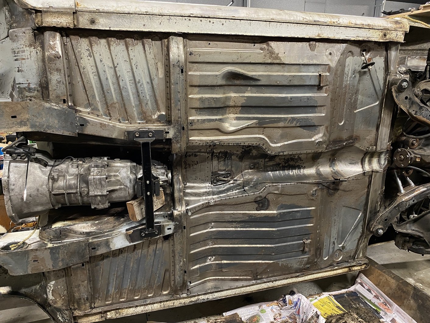
Was each side of the floorpan designed by people in different rooms who refused to talk to each other? The raised sections of floor are not visible inside, there is a second 'floor' that the seat bolts to. Those are pretty much identical. WHY the different shapes?! Is the floorpan also used in the Stag? Is there something there in the Stag?
- 201 replies
-
- 13
-
-

-