


flyingbrick
-
Posts
11652 -
Joined
-
Last visited
-
Days Won
2
Posts posted by flyingbrick
-
-
Forgot to mention. Defeat any shitty areas with tons of filler rod. Don't worry about how ugly it looks since you'll be grinding it flush before the final pass anyway
-
 2
2
-
 1
1
-
-
I have done this a few times myself on aluminium sumps (modifications to change bowl location, shorten sumo etc). So, old dirty oily aluminium.
As others have said.... Clean the crap out of it
Grind the top layer off so that it's not covered in a layer of dirty pores.
Weld it up as best as possible. It will probably throw a tantrum and the weld will be full of shit.
Grind the weld off (including the shit that's floated to the surface)
Weld it again.
I think I have only had to do the clean up grind once, but wouldn't be surprised if you had to do it more than once.
-
1
-
1
-
-
Yup Its a bloody trap
I believe it's there so that as you unscrew the ring it pulls the collet out of the taper.
-
1 hour ago, Adoom said:
I got one like that a few years ago. Similar price. Also from banggood.
Only issue I had was a ridge inside the retaining nut thing that prevented it from working. Since I had a lathe, it was real easy to remove that ridge so it worked. That may just has been an issue with the batch mine came out of.
The are accurate enough for what I do.
Sorry if this is a stupid comment, but I'm surprised so many people don't know this...
You don't mean the ridge that the collect clips into?
-
1
-
-
Test dick and balls
-
Yeah I had to pay to get the simulation features. Bloody expensive at near $100 a month
-
39 minutes ago, NickJ said:
You understand how much i'm banking on this then!
So getting the axes to work is pretty good as once one runs, its pretty much copy/paste but.....
The X is 3.5m long and currently half buried under usual shed stuff so its out for testing on.
The Y is 1.5m but if running away would smash the side of the Datsun.
Which leave the 250mm of Z as the obvious to test on, except it has a brake which if released too soon dumps down to full negative, tripping the overtravel alarms and because I never noticed, then spend an hour trying to find why the servodrive enable contactor wouldn't pull in....So the only way to test each axis is to drag the Datsun out into the carport, clear the table (just in case) and test on the Y axis.
I'm reasonably confident that once running the VFD will be straight forward then a full dive into classic ladder to enable all the required pneumatics, my hope here is that there is pretty basic feedback so at least trial and error has a better chance of success compared with the software oddities currently plaguing me.
Oh, and then a G-Code refresher
Followed by hasty CAM refresher
And likely forking out for Fusion360 to get all the toolpaths
It's f360 cam not free?
-
On 04/07/2022 at 22:26, NickJ said:
Fricken mail day!
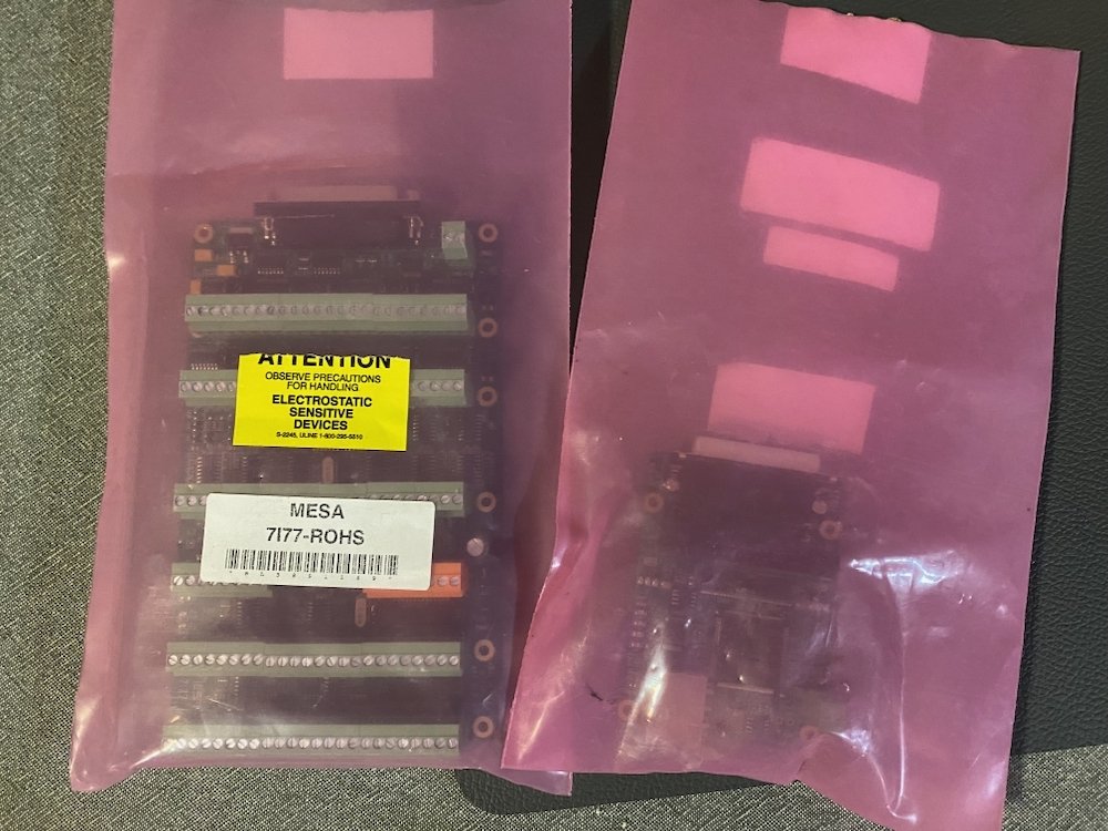
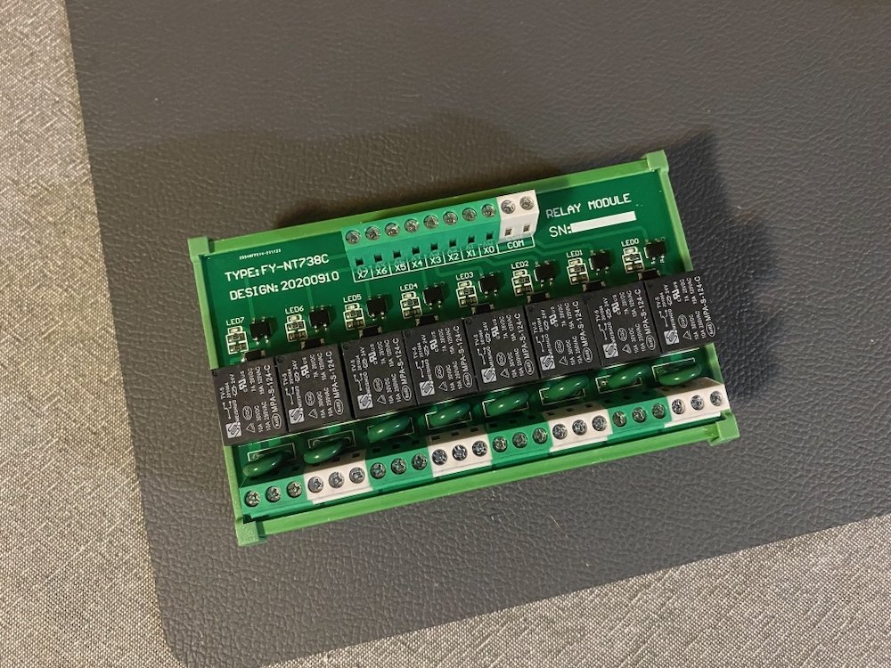
7i77 6ch servo control board and 7i92 Ethernet board.

8ch relay output module, I expect many more of these to end up in the system, this should be enough to get started.....
On lesser (But way more important issues) Loading Linux onto the computer has been a ballache of learning about stuff I care little for. It turns out Debian(OS) and linuxcnc are not friends which I lost a few evenings trying to figure out, that lead to a copy of Linux Mint being wired my way "Just hit load"
Yeah right
Kept getting a "Grub2" error, who? what? eh?
So i've now learnt more acronyms that still mean little but the gist is;
-Enable legacy boot (in BIOS)
-Custom install partition table
-reserved BIOS, swap and main partitionsWith the OS loaded to the hard drive, a healthy reward was the latency dropping from well in the no go range to well inside the preferred range, stoked.
Another weird issues was the cheap VGA adapter, for some bizarre reason boot screens don't pass through meaning I had to borrow the girlfriend's office monitor to fiddle in the BIOS, this had me thinking I had bricked the computer until sanity suggested the logical problem solving technique of trying a different monitor....
Slow progress, but moving forward and closer to hardware movement!
Good morning friend.
Why didn't you install that pre-compiled (I think thats the word) version of linux that has linuxcnc pre-installed? That's what I set up on mine and it works great (jitter is a bit shit but within acceptable ranges)
Does that pendant interface with the mesa card?
-
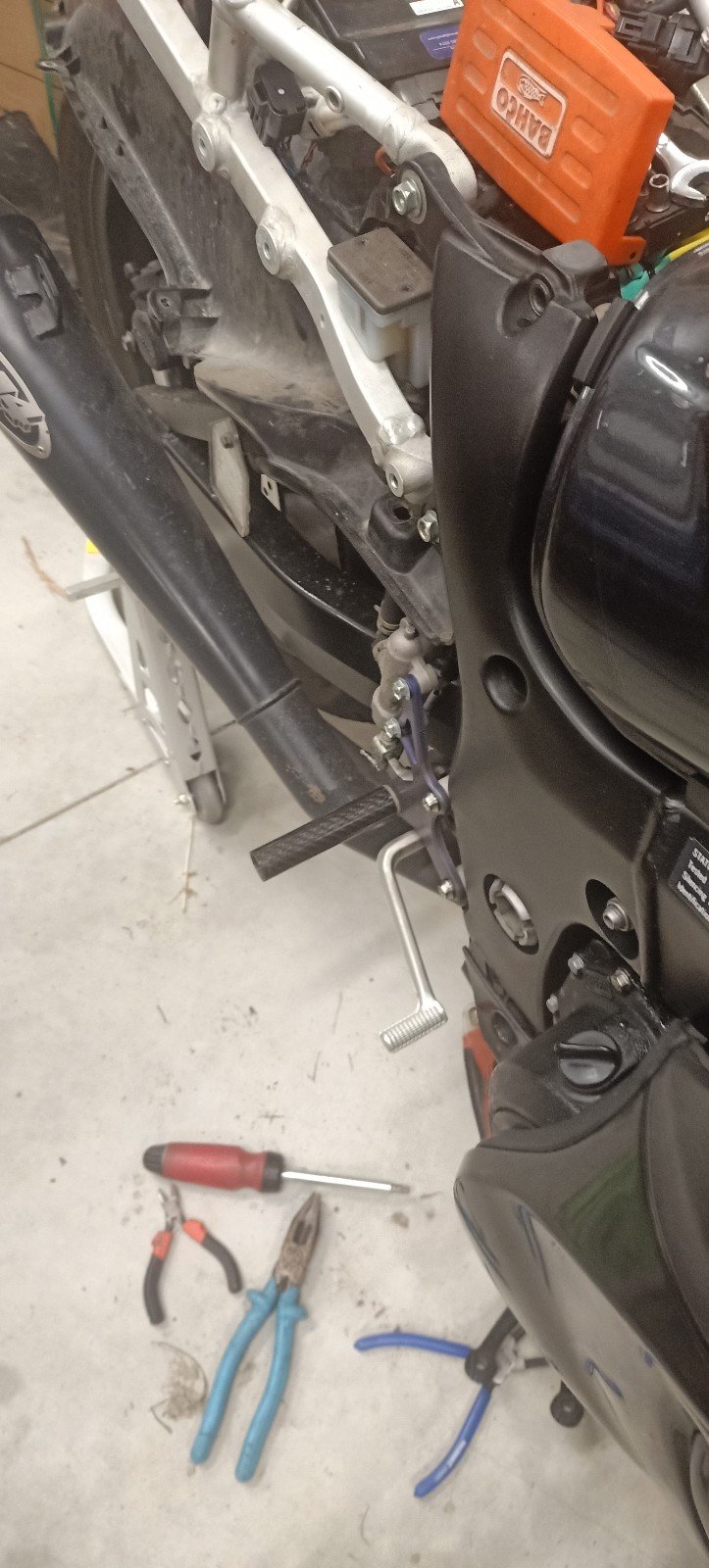
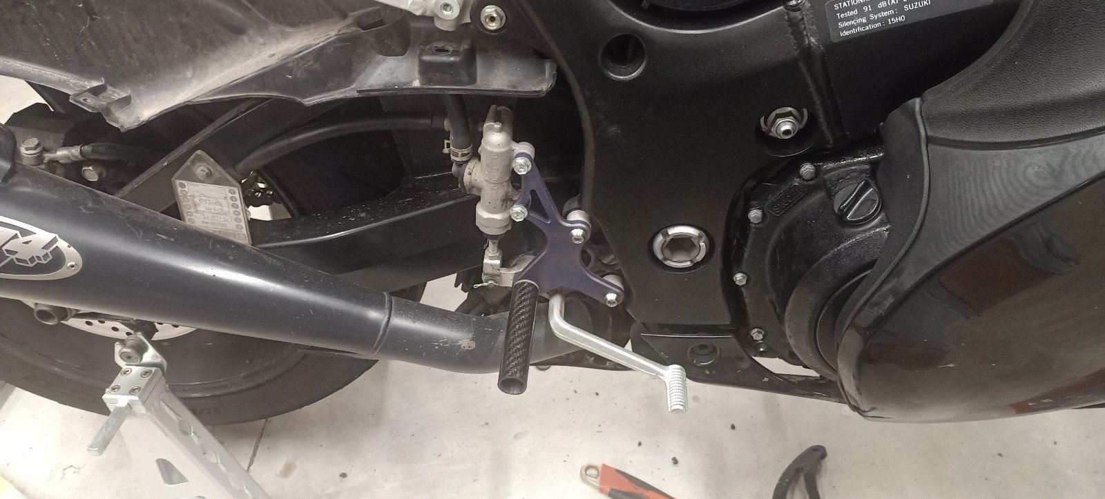
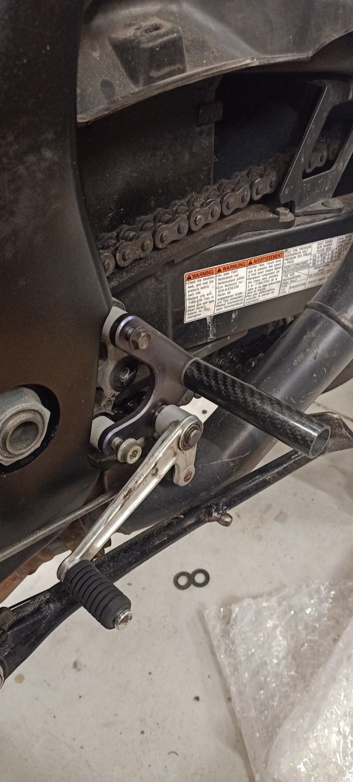
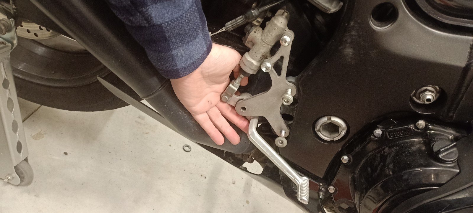
Right hand side mocked up to check for any serious issues. Everything works as expected.. Which was kinda unexpected.

The factory brake lever looked heavy to me but is actually exceptionally light.

-
5
-
-
4 hours ago, anglia4 said:
Nicely done.
Those carbon foot pegs look ultra slippery though!
I would highly recommend spending a few grams on some skateboard adhesive grip tape to put on them. I did this with the nylon pegs on my bucket racer and it makes a massive difference when you are riding. A+++ wouldn't ride again without it.
When I was picking up the aluminium bits from @Kimjon he says to me "how are you going to stop them being slippery"
I say, "im going to get some skateboard grip tape" and he's like " brb" comes back with a roll. Such a good chap! Grip tape is not on the pegs yet in the images- I wanted to abuse them a bit first with a hammer and with protected legs jumping up and down...it passed
He's also just machined up the steel pivot boss thing for my brake pedal. So dreamy.
-
6
-
1
-
-
5 hours ago, Willdat? said:
Such a cool project, do you mind sharing the cost of the titanium cnc plates and the suppliers as this would be reallllllly useful.
Of course.
I used a company called YUNCH, contact mandy.shi@yunch.tech. First class service. The cost of these two plates was just under $200. half of this was freight. Next time I'll be pushing for use of a cheaper freight option (But this was very fast, so i cant complain). One tip is to search AliExpress for services. Often they will have a product for $1usd. You purchase one unit, send them the drawing etc, get a price, then pay the rest of the bull by purchasing more units. This also means you get access to that super cheap (But slow) AE shipping.
Although that $200 may seem expensive, that is material, freight and cutting.
-
5
-
1
-
-
Hahahahahaha actually laughed out loud
-
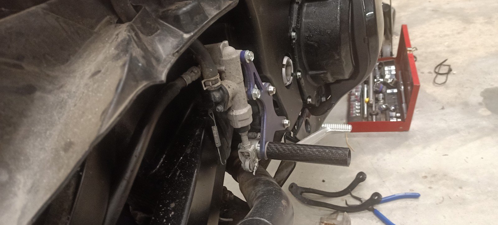
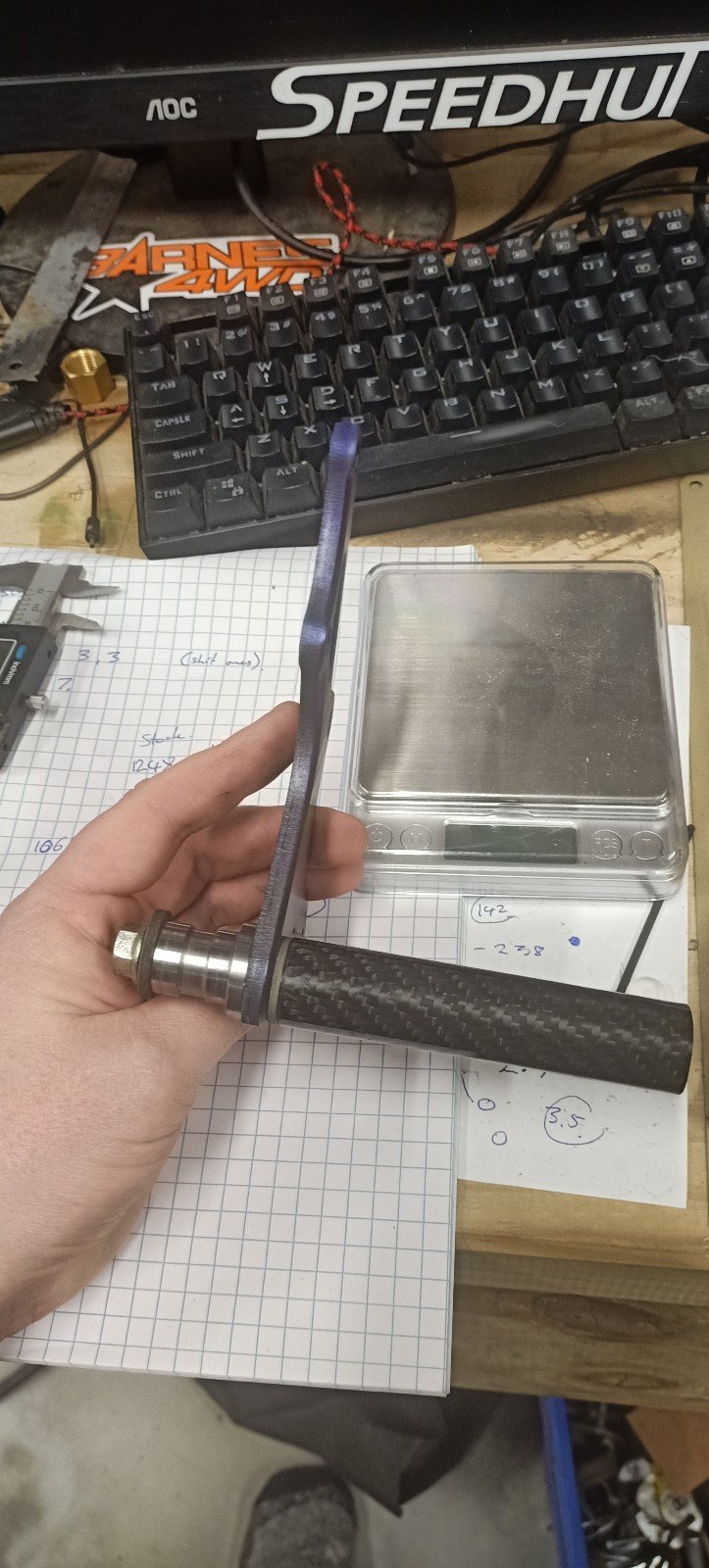
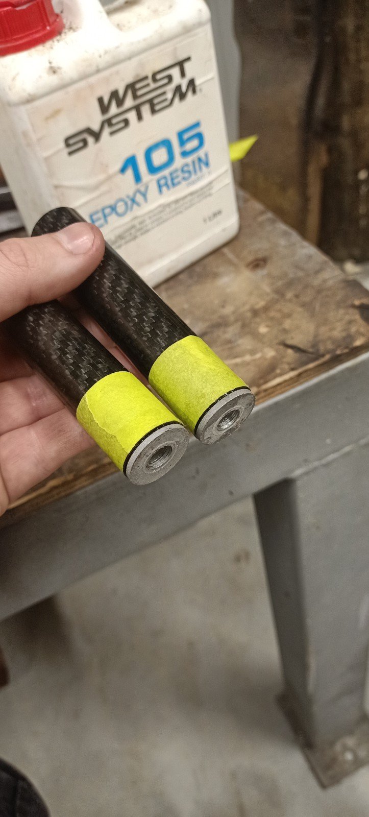
Left hand side peg assembly nearly complete.
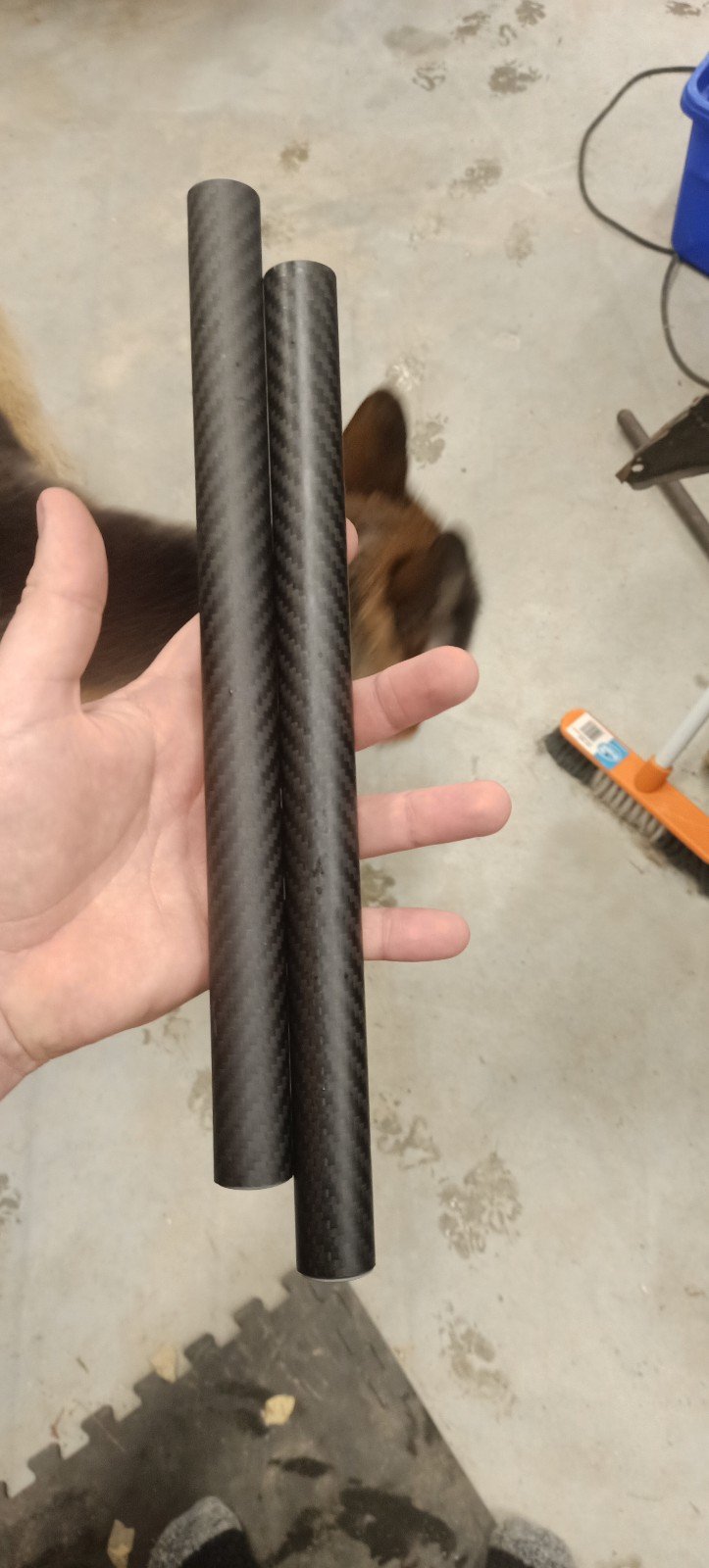
Carbon bars
Titanium bolts
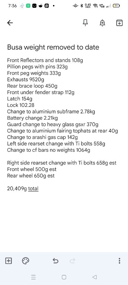
Iv got some assembly to do once some fasteners etc arrive but on track to a 20kg reduction vs stock weight. Enough to be felt! Once assembled that will likely be the end of this project because any more weight removed becomes fairly expensive...unless I can be bothered trying to mold some fairings.
Edit. Just spotted, total is already 333g too optimistic as have counted front weights twice.
-
5
-
2
-
-
On 03/07/2022 at 10:20, kempy said:
Noticed that too with auction sites on TM, stupid stuff like cheap Ozito tools going for much more than retail :/
English wheels seem to be quite expensive for what they are, to the casual observer
I guess they are big and heavy so freight costs for each movement is going to be extreme. Also, aside from that, damn the one in that auction is a sturdy piece of kit. I'd love a weekend with one just to get frustrated enough that I don't want one any longer
-
1
-
-
Gotta admit.. At first I didn't understand. But now we are 25 pages deep and I find your stuff quite impressive
-
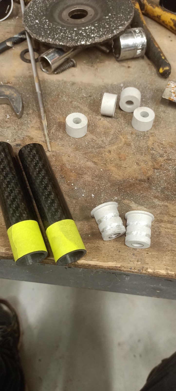
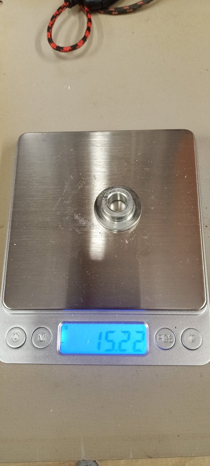
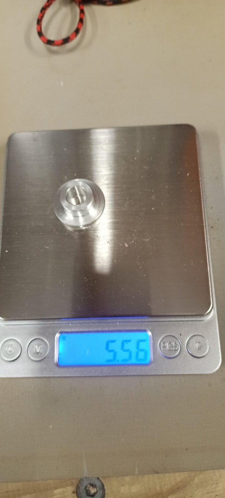
And I replaced all of the bikes steel tophat bushes with aluminum items, made in NZ this time.
-
8
-
-
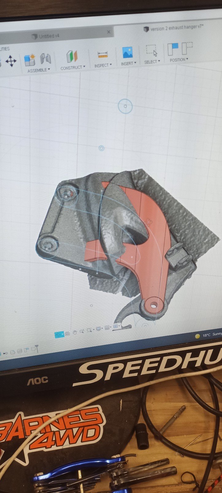
The exhaust hanger thing was still Happening in the background. It's a tough shape that has to come out of the factory fairing in a very specific place.
To double check it's shape (so that I didn't waste any more of Davids printer flament) I took a scan of the factory part and merged them together. This worked extremely well!! And yes, it fit.
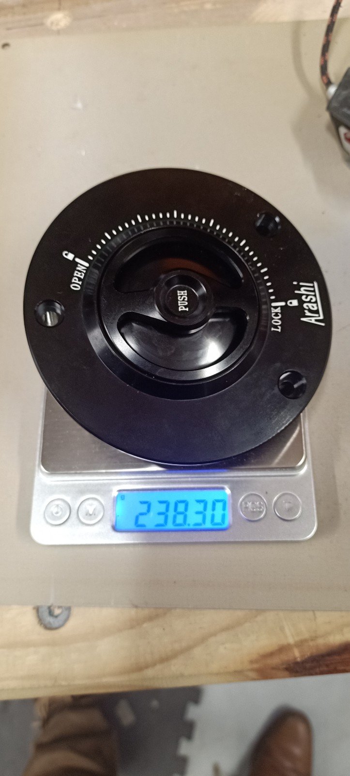
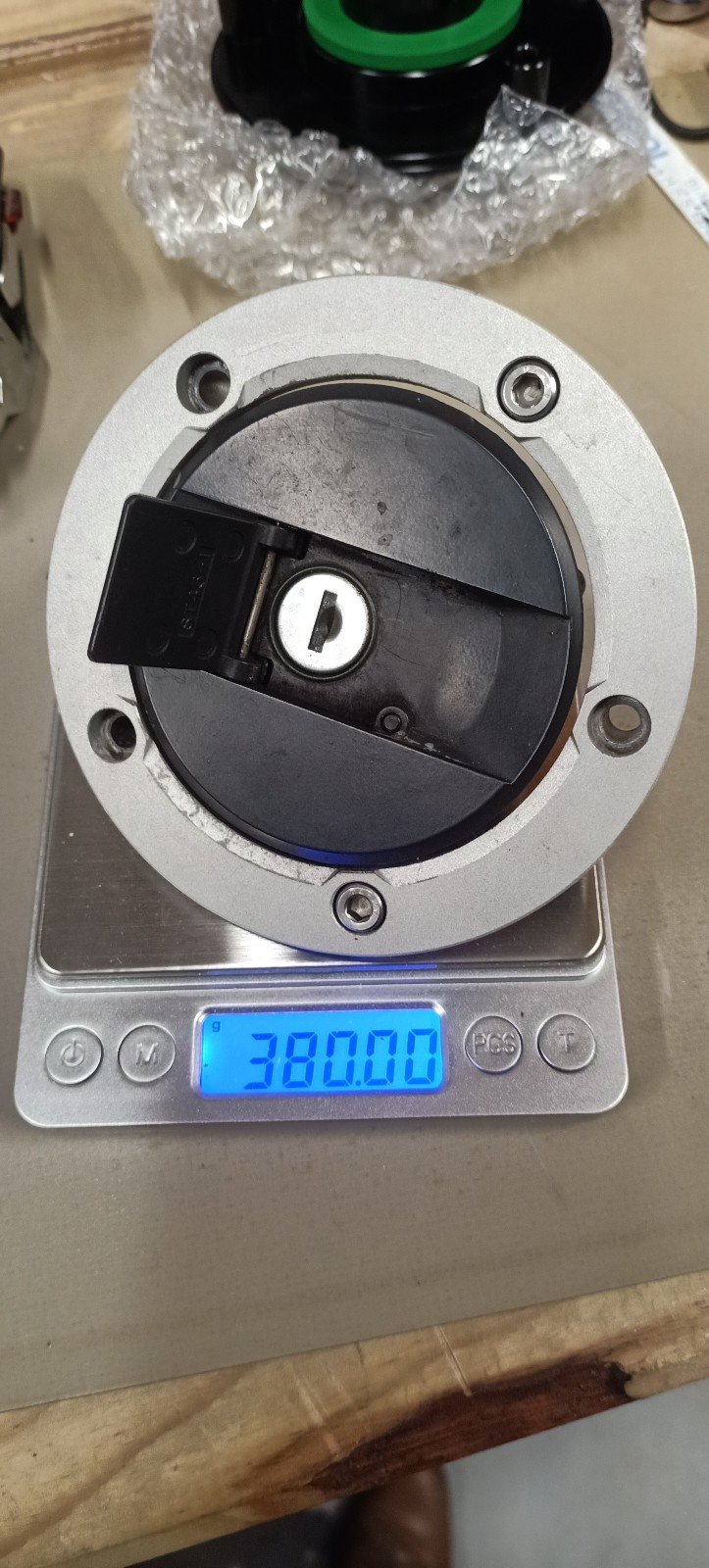
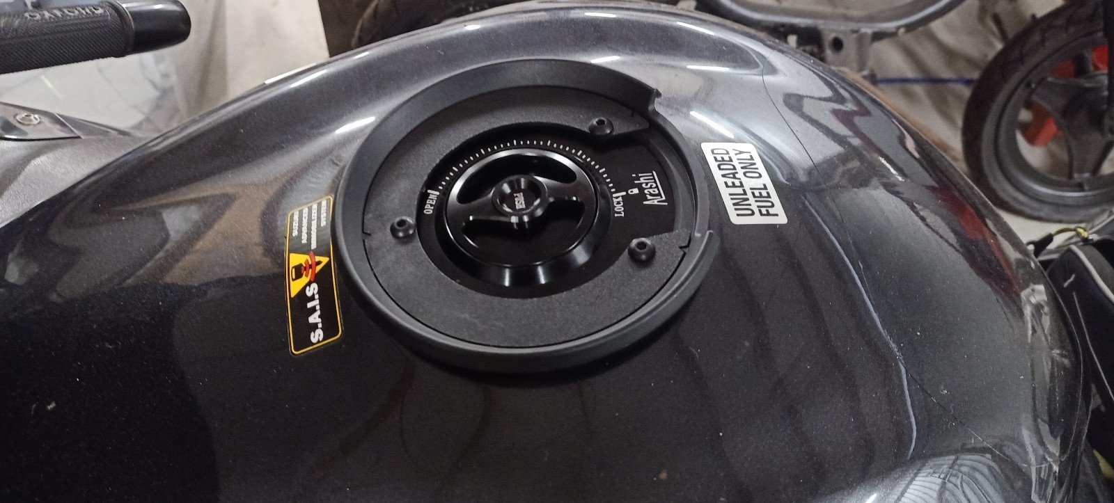
Ali express provided a new light weight fuel cap for an insanely good price. Very happy with quality too
-
3
-
-
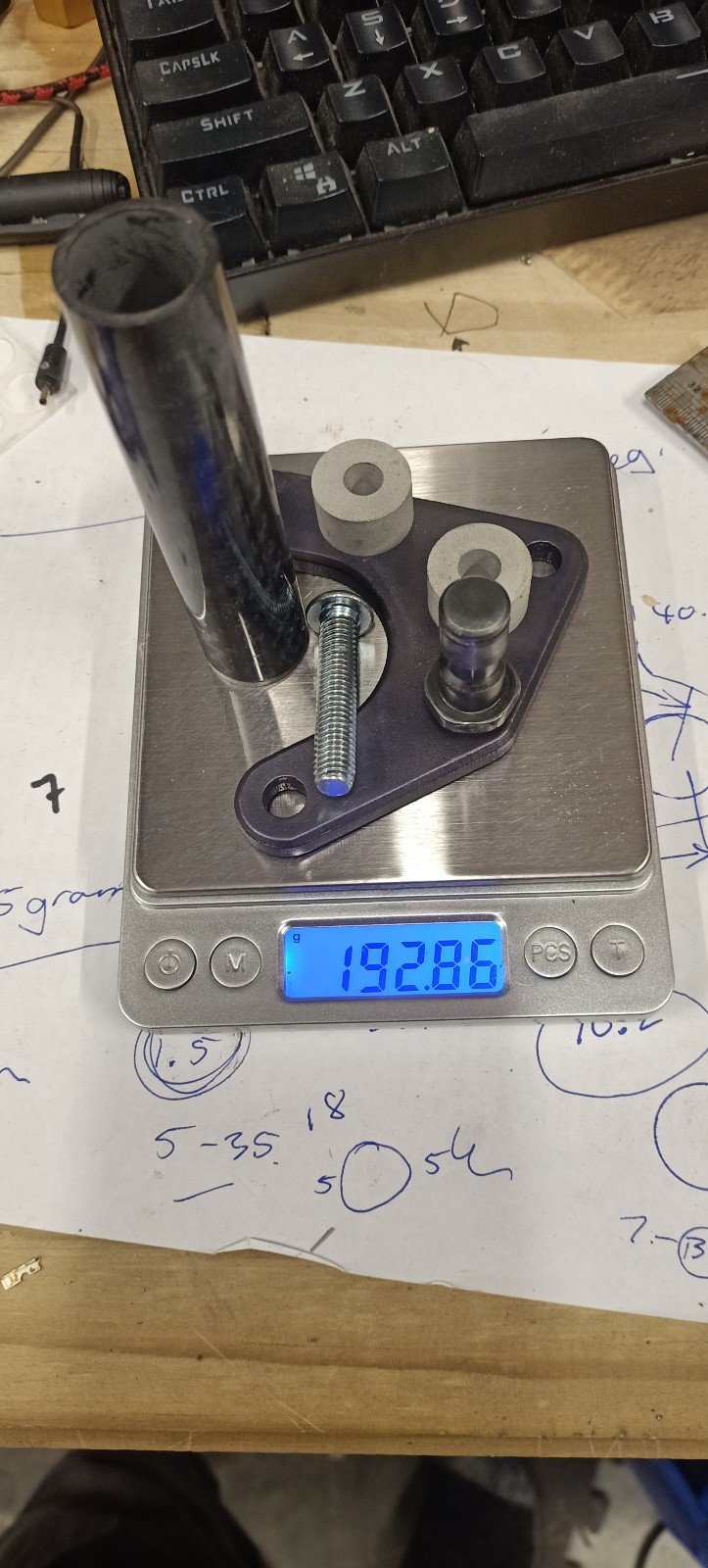
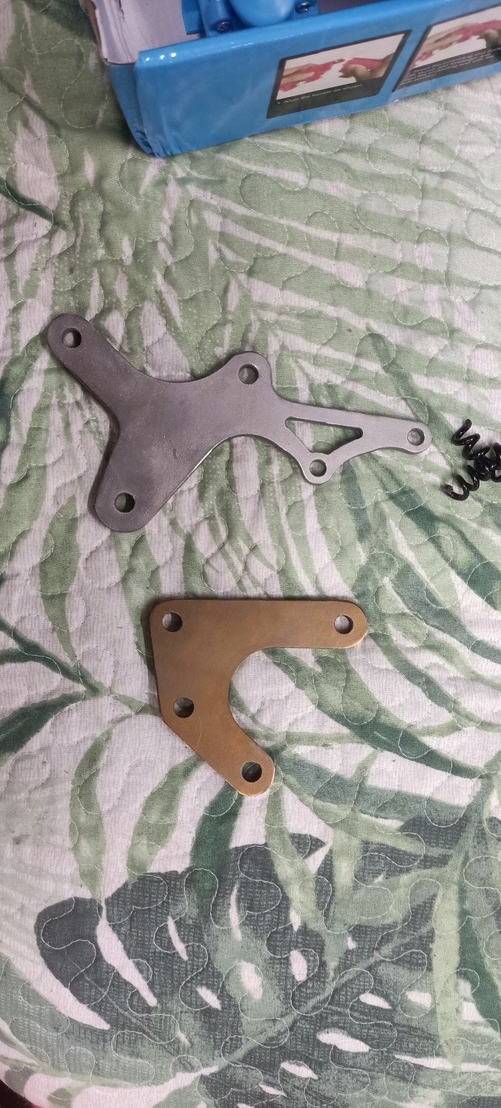
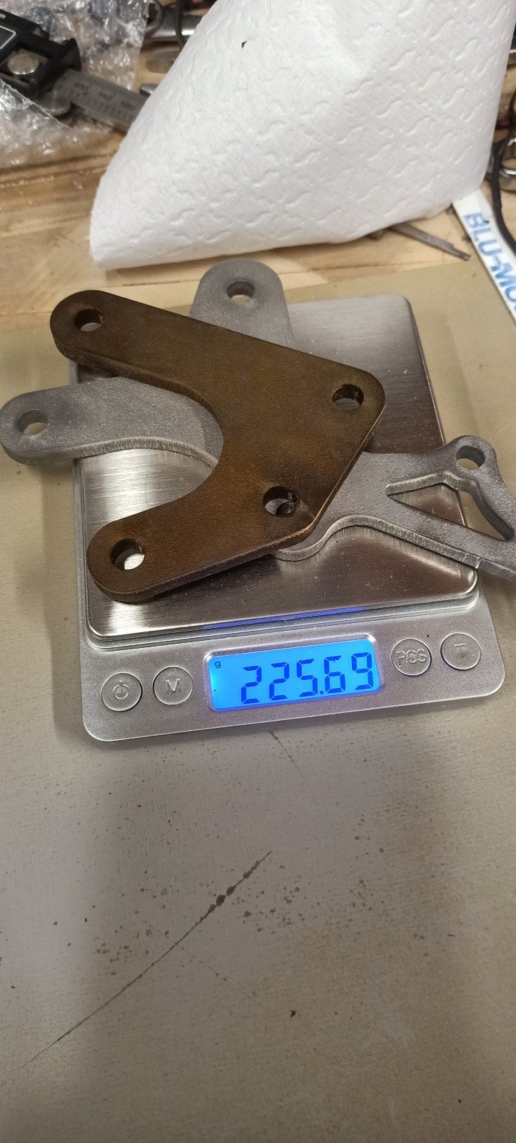
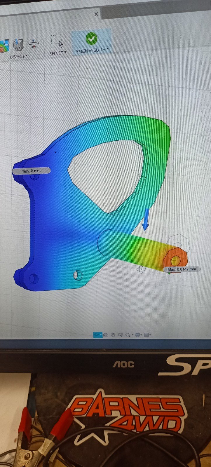
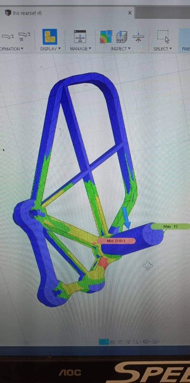
So I started again with grade 5 titanium. By this stage I'd stopped taking photos as I'd run so many simulations it was getting a bit old, but the results were good, the anticipated weight of each component was great, and I'd never played with titanium before so seemed like a good time.
I sent some emails out within NZ and China. Its sad because companies in NZ really can't be fucked with smaller jobs and the associated admin. I got a few replies after waiting a few days and these replies ranged from not being able to secure the material (they couldn't be bothered) to having a minimum cut fee which made this only economically viable if I got three sets cut (I ain't paying for enough material to make that happen).
China made me feel like a king with absolutely great customer service, though I was still not 100% that I wasnt getting scammed... But after a few weeks my titanium rearset plates arrived!
I haven't had much time for filling around but need to tap some holes and buy some pegs, then they are good to go on permanently. Weight saving from the change to these Ti plates is 500g, however when I include the change to the associated light weight pegs, nicer bolts etc will be well over 1kg.
Colour change is due to some DIY anodising- super easy with titanium!!
-
6
-
-
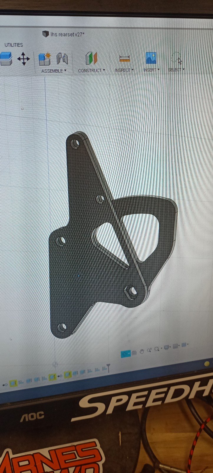
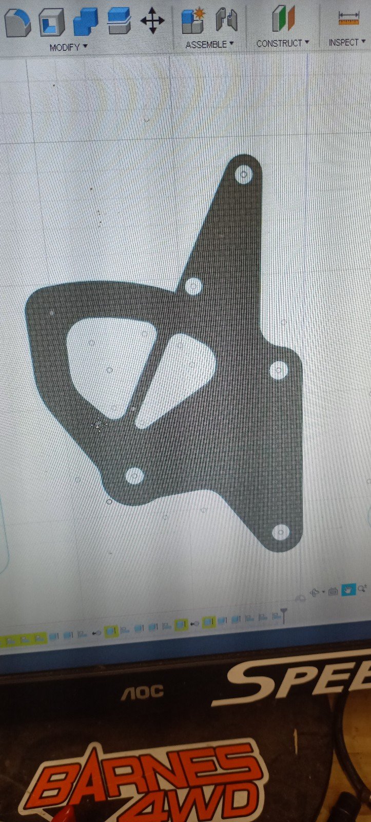
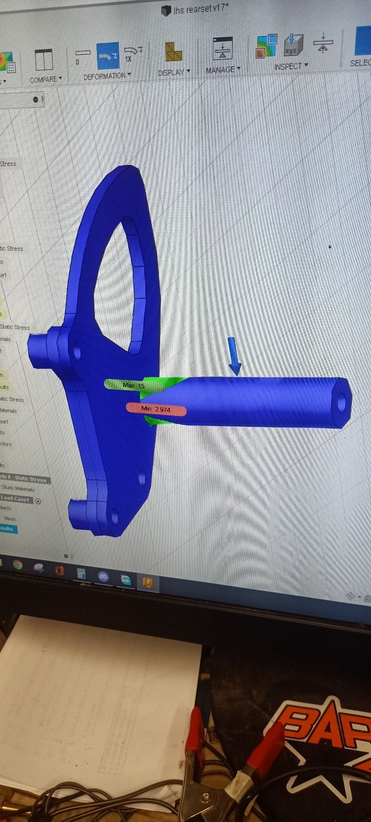
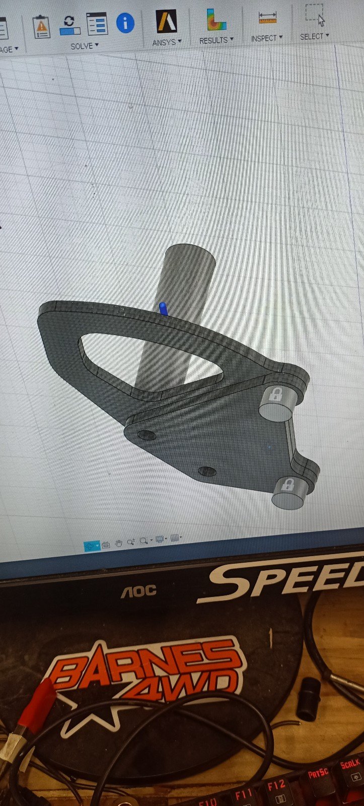
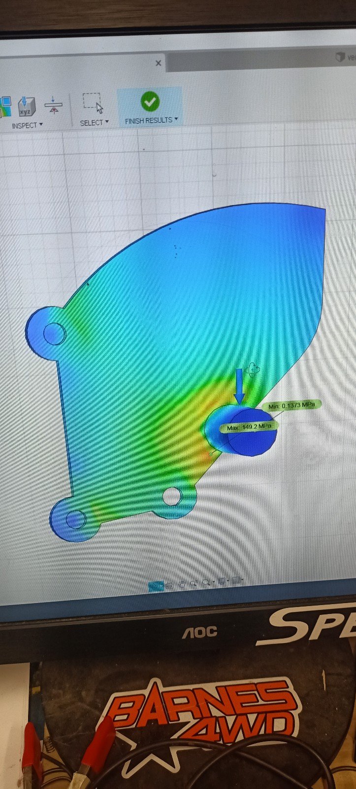
I decided to make my own, initially out of carbon fibre plates that would be waterjet cut. This was very very interesting as ended up using fusion 360's simulation package to calculate my designs strength. I ended up getting absolutely insanely strong parts designed in CF but at the last moment got a message from a friend (experienced in composites) saying STOP COME VISIT ME FIRST.
He gave me an extremely valuable lesson on carbon fibre strength and how f360 was not actually giving me an accurate simulation, and although they may work, the properties of cf plate were always going to place a question mark over their suitability and working life, so back to the drawing board!
-
2
-
1
-
-
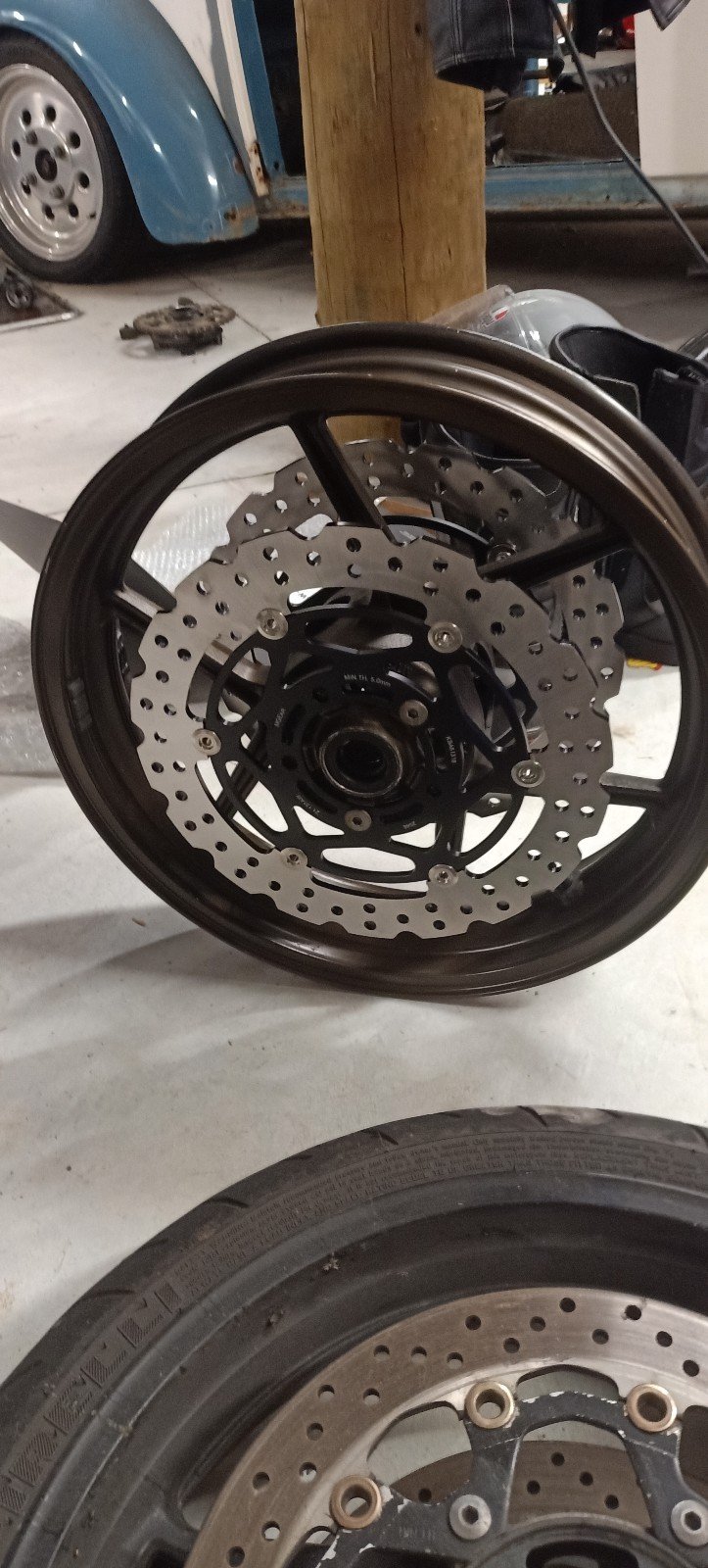
Disks to suit the zx10 wheels turned up and some little aluminium spacers are sitting at work. Aside from getting a tire fitted it's all ready now to go back together
 will be interesting to do a proper weight comparison (need to get tire pulled off the factory wheel first).
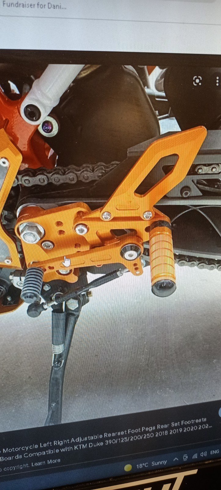
I have wanted aftermarket rearsets for ages but $$$ and I'm never happy with how the aftermarket rearsets all seem to be a series of aluminium plates stuck together with adaptors. Jankey as.
-
1
-
-
1 hour ago, Roman said:
I think you could be right about that.
If the piston is trying to fly apart, where the top of the piston is trying to carry on upwards, and the pin is pulling it back down.
So the material strength around the pin is the weakness.
Then on the exhaust stroke this force is lessened, and when the cylinder is full, on the compression stroke this force is lessened too.
The engine didnt fail when it was approaching max rpm, it failed just after a gear shift where throttle got cut to zero.
So the worst case scenario would be zero throttle, high vacuum, high rpm on the compression stroke.
I'm not sure if these forces are on the same magnitude as each other though.
However, I can indeed increase my piston return spring value.
I can use e-throttle to set a minimum high rpm throttle value to something like 10% or 20%, and then use a fuel cut and/or pull zillions of ignition timing out to cut power instead.
This might bring a host of its own issues, but might be a bodgey solution I guess haha.
Flat shifting, interestingly enough, would also help haha.
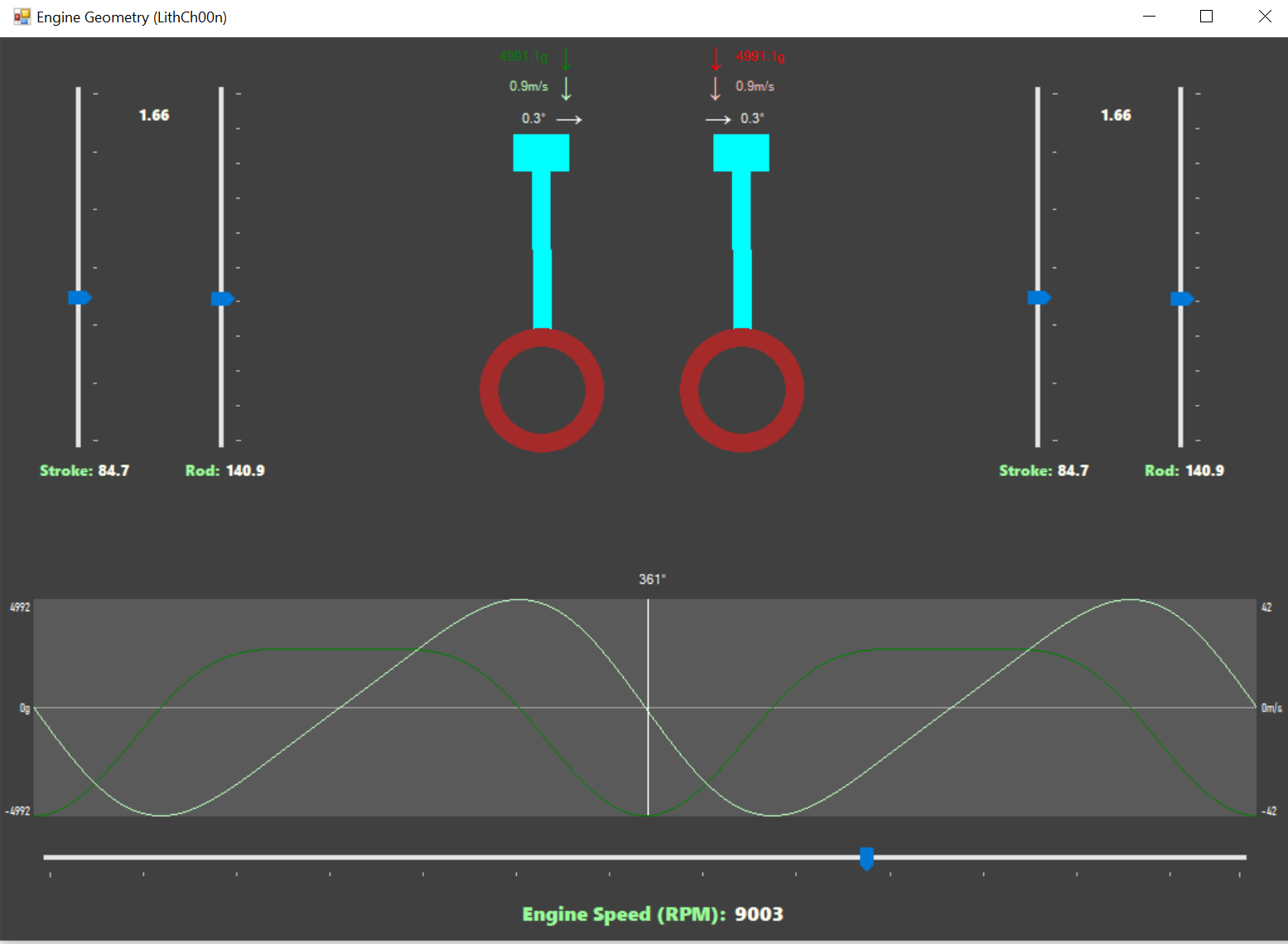
The incredibly clever @Lith made a calculator ages ago that works out forces on pistons/rods.
Entering 1NZ stuff. Peak accelleration on the piston at 9000rpm is 4991G!
I'm not sure what sort of numbers I was expecting, but thats bloody lots.
Then the PEAK piston speed is 41.7 meters per second. Which is 8200 feet per minute.
Which is zillions high when 3500fpm is the reccomended mean value.
interesting. That could be around 1500kg yanking on the rod, which would have a yield of like 15x that, but I have absolutely no idea what im taking about.
-
-
Hey guys with linuxcnc, what you doing for computing hardware and interface board, and what jitter readings do you get?
-
Anyone got some big old steppers to re-home?


Italian shed ornament - Nick's cnc router repower
in Other Projects
Posted
How do you earth a 5v supply rail... Damn that's got me confused. Do you mean the 5v power supply itself?