kpr
-
Posts
3,390 -
Joined
-
Last visited
-
Days Won
2
Everything posted by kpr
-
Probably all denso ecu's have leaky cap syndrome around those years
-
short answer - yes itb's will need a vastly different tune to a single throttle
-
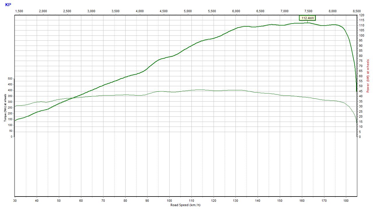
stock vs "ported", not bad gains with the little factory cams. not cracking 110kw was annoying me. so ran it up at 100deg oil temps. what a weapon.

- 124 replies
-
- 12
-

-
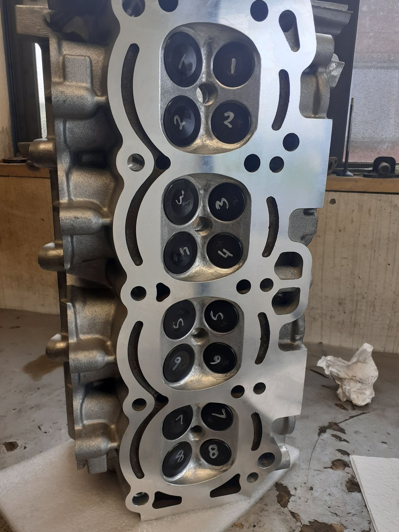
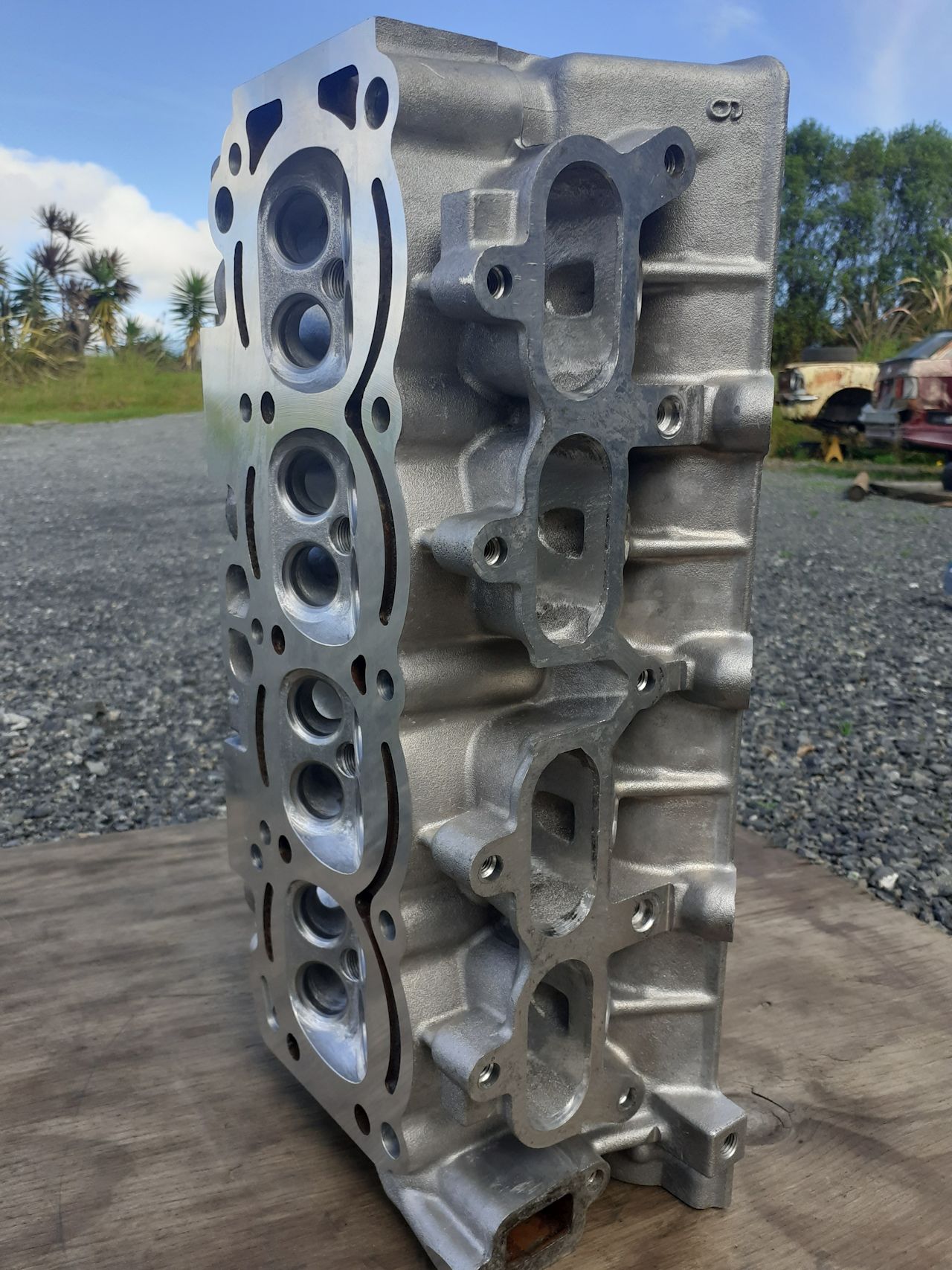
^was cool till said it was 1900cc 9a thingy. Just finished putting this on the junker engine today. Its the early bigport head. have modified the ports and chambers. mostly around valve area. its all just straight off the die grinder finish, because polishing and making it look pretty is a waste of my life. initial run up today looks like have made some improvements, as required bit more fuel 5500rpm onwards
-
Try garage4age discount code on the maxpeeding site. Not trying to be there salesman but maybe worth a look if it makes them cheaper
-
I've got some maxchina rods here. because youtube deals. haven't measured them up yet. but they look all good and weigh all the same within .05grams. they do have the usual china finish lacking attention to detail. like after they have machined the big ends to size, there is little burs left in the slots where the bearings sit etc.. nothing that a little hand finishing wont tidy up tho.
-
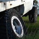
yeah they sit under the steering knuckle, to set the preload on the kingpin bearings. Used on live axle front hilux's and the likes. They usually come with axle rebuild kit's. so no great value or anything
-
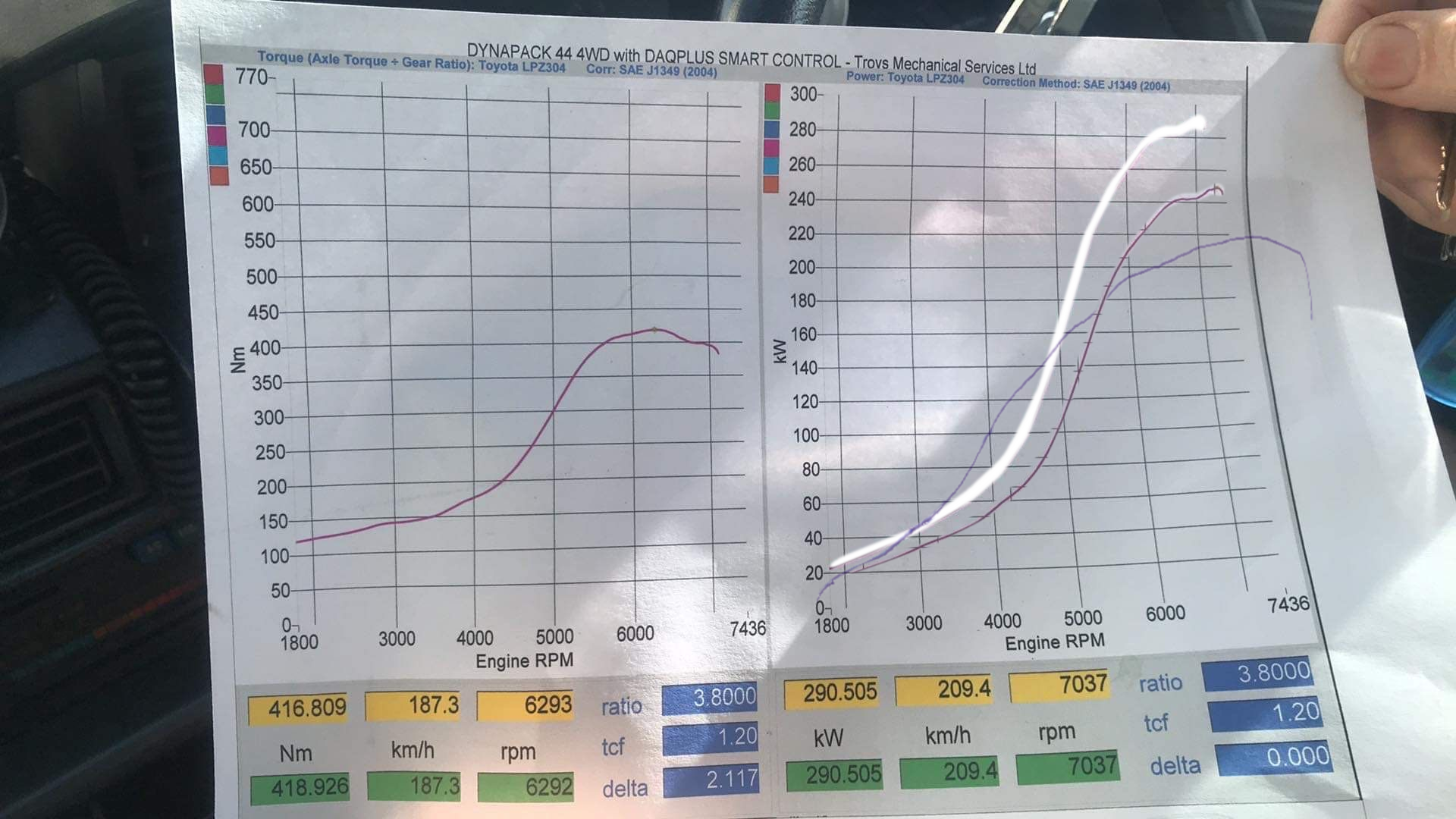
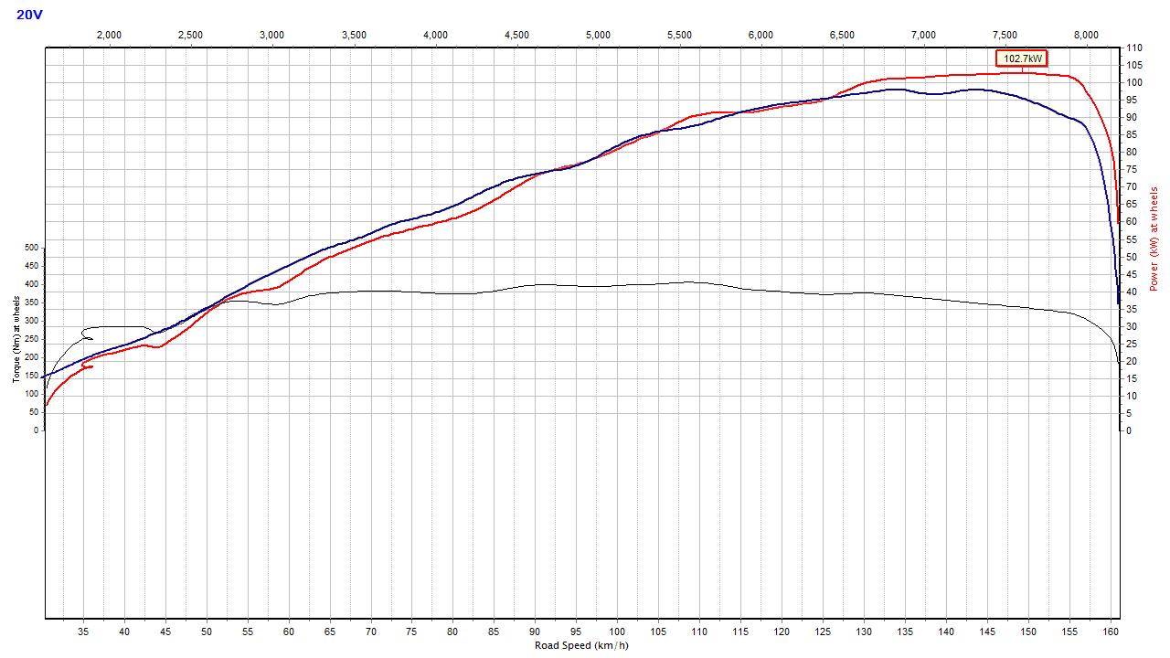
hmm yeh the usual not everything as it seems. The dyno sheet has a 1.20 tcf. which im pretty sure is the correction factor they have added. so the 290kw is more like engine power, not wheel power. but 1.2 is pretty generous for drive line loss. heres about what it would look like in kw at wheels. I overlayed a run from my turbo setup at 16psi. which shows how yuck the power curve is also
-
If you go on my channel there is a playlist "gold 4age/ gold turd" it shows the build up of the basic smallport setup
-
if just want a little more power can turbo the na engines. otherwise yeh ze. although they are just the same as the na engines of same year bar pistons. so a piston swap = ze engine. I would suggest doing a basic rebuild on whatever you use. pretty much every 4age dies by running a big end.
-
Not really going to do a guide as such. more showing what can be done with the right parts. As some of the parts im using or the equivalent of cant be brought off the shelf or fit in any chassis. one thing in the wrong place on a na setup can turn the whole thing into a turd that doesn't work. depends what you call ok power. but I think I already built said budget engine. which was the engine before i swapped the bigport head onto this one. basically a smallport block and head with a few little tweaks to head. 193b cams and good bolt ons 130kw at wheels on a good day. Im just messing with a bigport head atm to see if can get same results as the smallport. turbo definitely easier, make more power and run nicer. cant say ive tested it, but old mate's on engine masters seemed to get decent results from running cooler fuel. I have my fuel rail pretty well insulated from the head for that reason
-
no leads on housing sorry Yeah you are right. it needs to go to the top outlet, or block it. since the water isn't being cooled by the heater core. I just run mine blocked off if no heater, as thats essentially what the heater valve does. some people say the head cools better if return it back to the top outlet / radiator. but haven't had the motivation to try it myself
-
yep, lighter internals, better head better cams. You can thank the 4agze for creating the bigport redtop turd. seems to me they did the changes to suit the 4agze, then just made the na engines the same with a piston swap.
-
No idea. Too much mahi to measure
-
Another question thats been around since the beginning of 4age time. Answer is as expected, Bluetop cams are a tiny bit better. as tiny bit bigger
-
Can i make my bigport head have smaller ports, if i put pimples instead of dimples in the ports ? I'd try it but there is only so many times one can swap a 4age head, before going insane and thats coming up real fast. Agree with what @Roman says about the fuel sticking to the walls. dimples only going to help when it doesn't need help. one of my vids i done with camera looking down the port. the fuel all chills out in one of the mismatches where 2 parts of the intake runner joins. soon as open throttle a decent amount. the fuel gets pulled out and goes down the hole with the rest of it. so dimples probably just give the fuel more places to chill out when airflow is low
-
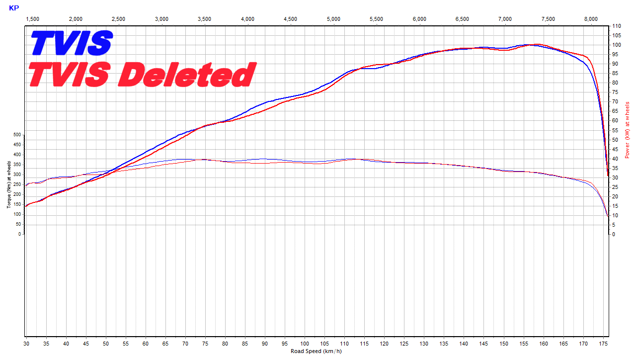
car hasn't made it off the dyno much in the last few months, not sure if the front wheels still turn or not. but would say its definitely noticeable. Changing between my big and small headers effects the 4-5000rpm region, its a bit more of a change than what the tvis does. but is a night and day difference with how the car drives. As you say if look at it percentage wise is more of a gain than it seems. Not the best example. but stockish bt 20v in fwd chassis vs the early bigport with tvis with good exhaust
-
20v just the 2ZZ of 4age. Mocked just because. The 16v does have a far bigger area for the cams to act on especially when go shimless/ shim under bucket. So can run far more aggressive cams in them.
-
4age is a dunga also. so guessing jamming a few more cc's up it doesn't really polish the turd much. Just pulls the powerband down the rev range. then people failing at using wrong bolt on parts, means makes no bottom end either. maybe i should get a 2zz
-
not worth it for $$$ imo. 4age can make a decent engine with stock parts. 7a you have to spend some money to make them as strong. and silly 6 bolt crank. Just use a 4a and rev it more.
-
Ive got a supply of genuine head gaskets i never used from engine rebuild gasket sets. but current one is on round 3. it stuck to block both times and the top looked mint. so on the head goes!
-
oh dang i just noticed that the rpm is off in that graph, which means i forgot to change the rev limiter on the itb tune. soo turns out 35 year old stock valve springs are good for 8500rpm haha
-
Wash your mouth out with that 20v talk. same for that turbo talk From memory the 1g valves are really small. 4age isn't too bad but can go bigger. which requires new seats installed, so starts to get spendy. but yeah both oversize ports. I find it amusing how its the total opposite of what people think. bigport will be good for more top end power..
-
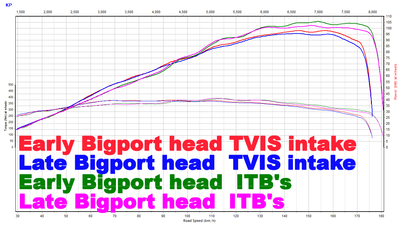
Port shape seems to be the difference between them. smallport best shape most power. early bigport 2nd best. worst is the late bigport. I just finished testing the one @kyteler sent me. its a few kw down on the early head in the top end. both with stock intake and itb's. It has the biggest ports all the way to valve out of them all, also has a shitty short turn radius. So yeh, thats why redtop bigport is such a turd. Not sure why mr toyota made the later heads worse, maybe the engineer behind it was like screw this fwd junk
-
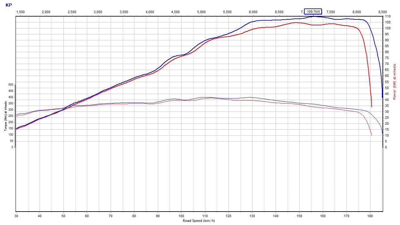
Soo, turns out the tvis wasn't opening all the way. thought results seemed weird... vid has been fixed and reuploaded / heres the graph.