Roman
-
Posts
6760 -
Joined
-
Last visited
-
Days Won
32
Everything posted by Roman
-
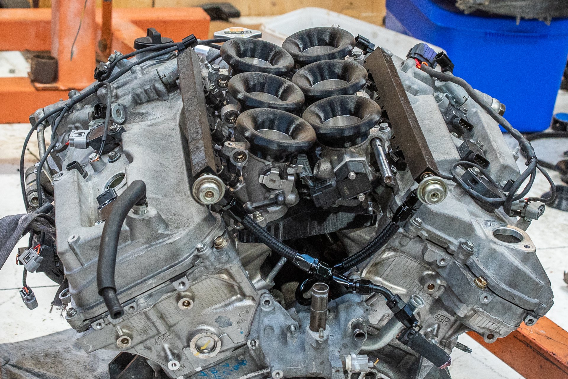
Slowly getting there! Once the proper fuel rails are fitted I should be able to fire it up which is exciting. The clutch fork situation is not working out well so I'm borrowing a concentric slave from @Sungai Sungai to see if that will work. Looks like it should be good with the right sized spacer behind it. Most of the fuel lines are all finished. I've mounted the corvette fuel filter right down by the tank, so there's now only one main fuel line running to the engine. I finished printing some trumpets. Ordered some more AN fittings so I'll make it a straight tee at the back. Slowly getting there Still to do: -Drill throttle linkage rails -print carbon nylon version of manifold base -radiator mounts -remake firewall -finish exhaust -remake fuel lines -print housing for dash and fit dash -battery tray A few other things I've forgotten about. But just firing up the motor will be an exciting milestone. I've got no budget for exhaust parts etc for a while but I'm still making little bits of progress on the parts that dont cost anything.

- 653 replies
-
- 18
-

-
Good to see it out there again. Was meaning to come have a chat but I think you were too busy just racing the hell out of it. Awesome day!
-
Yeah I love what Doug does. And I just cant believe how damn fast his wagon is. So good!
-
Yeah I think it would be fun to build a rotary engine, I regret that I didnt earlier in life for a project. But that ship has well and truly sailed now, thanks to prices of things. A lot of the "classic" cheap and cheerful engines like 1JZGTE, 13B, 4AGE, 4G63, B18C... almost everything from that era you're paying an ever increasing amount for an ever increasingly pile of clapped out shit. It's easy to get stuck with the mindset that only that era of engines is good though. Or that K24 or LS1 are the only other options. But there are a few modern day gems I think. 1NZ was one of them I reckon. Hopefully the 4GR is too, but time will tell.
-
Also, Today I learn: When the fly wheel bolts fit into holes in the crank, that are open ended. Leaving the motor tipped backwards overnight results in a few litres of oil on the floor
- 653 replies
-
- 11
-

-
-

-
Yeah I started hoarding J160s quite a while ago, so I've got some with low kms. One has been in dry storage for about 16 years I think now... and at the time was bought with low kms on it. The other that is currently in bits, has less than 1000km on it. It was pulled out of a near brand new car under warranty. I've currently got my 4GR bellhousing on a third box, that was ever so slightly stiff getting into 2nd gear. But it's known good as I used it for many years with the last motor. Using this as the test mule. I've got a 4th good box in bits as well. Hopefully that's enough to get me by. Will do circlip mod if I blow a box up, but not anticipating it as necessary. Beams 3S makes 216nm of torque, factory 4GR makes 260nm. So it's not a huge bump. Generally with NA stuff the torque figure stays same-ish but you move it up the powerband. So its a lot easier on the box than a turbo ramping in zillions of torque at 3000rpm. With flat shifting and e-throttle blip setup (eventually) I think these boxes will have no trouble shifting at high rpm. As with an ignition cut flat shift you dont have to wait for throttle to ramp closed before you start making less power. You get the engines pumping losses working for you instantly, dropping the rpm really fast. The big question is still whether this motor can be turd polished to actually make power at high rpm haha. Cant wait to get it going!
-
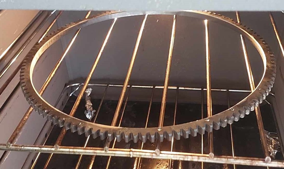
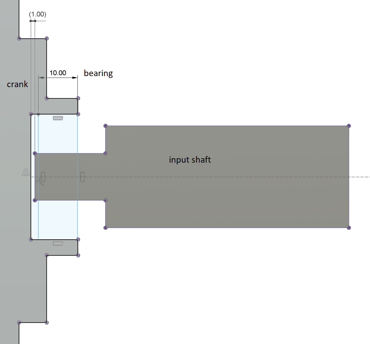
Flywheel situation Since the flywheel was otherwise a write off anyway, we decided to just skim it down until the damage was gone/negligible. Sooooo that actually works out alright. So test fitting it, first thing I notice that I havent allowed for at all or given any thought what so ever. Is that the end of the crank sticks out a bit past the bellhousing flange, then there's an upstand part which sticks out further again. 3S motor isnt like that. The end of the crank almost fully fills the hole where the spigot bearing is supposed to go. Crap. However, there is a hole in the middle of the crank to fit a smaller bearing in. Which is interesting as none of these v6 motors run a spigot bearing from factory. So, the 3S spigot bearing was 40mm OD and pressed into the flywheel. Other engines like 4AGE or 2JZ etc use a 32mm OD bearing that presses into the crank. Looks like that will work for this. Second panic attack - Was the nose of the input shaft going to bottom out into the end of the crank, or be too short to reach the bearing when fitted into the crank? Fuck. No idea, cos I hadnt given this any consideration at all. I'd picked a fairly arbitrary length to shorten the bellhousing by. So doing some measurements, it looks like I've managed to bullshit my way through this one successfully. The 10mm thick spigot bearing will be alright. I've never heat shrunk a ring gear onto a flywheel before. Dad machined the OD of the flywheel and the ID of the ring gear to the appropriate sizes for heat shrinking on. Some calculations showed that ideally the ring gear ends up 0.6mm too small to fit over the flywheel when cold. Then it expands to larger than the flywheel size when heated to 150+ deg. So this was stressful. As it cools really quickly, and if you dont get it in the right spot I'm not sure if there's a non destructive way to remove it. It took a few goes, because I'd not had it hot enough to slip over. So when it finally did, it caught me by surprise a bit. However I managed to get it in the right spot, and tap it straight before it had fully cooled in place. Not something I want to do again any time soon TBH. Then the next issue that steers this project one way or another. Was going to be whether or not the tiny lithium battery would be able to crank over the motor okay. Turns out its no problem at all, and ring gear distance/engagement is fine too. I also managed to build up some oil pressure, which proves that the sump is doing sump things. So the next steps are to buy some more flywheel bolts that suit the thinner flywheel (4AGE ones are now the right length, which is handy) Then put it all together, put the clutch on. Mount a slave cylinder. Now that I know the battery will work out fine, I can start making a battery box, and connect everything up. I'll theoretically be able to fire it up once my intake is finished! I'm sure my neighbours will be delighted to hear some open headers 350Z trumpet noises.
- 77 replies
-
- 38
-
-
While sharning about piston speeds. The StanceWorks K24A powered Ferrari blew its motor recently which is a pity. However it was running to 9500rpm with 99mm stroke. That's 6100 ft/min piston speed. Whether or not they were running on low boost, thats some crazy shit. That motor was not long for this world!
-
I already have. Got the Kelford springs and titanium retainers in there. Will be interesting to see how the factory cams can go when able to spin up a bit higher.
-
The 2GR heads will be best, since they have huuuugggggeee valves because of the much bigger bore (94mm bore vs 83mm 4GR) So as a result the valves are 7-8mm bigger diameter which is crazy. If you put a 2MZ crank into a 2GR then you end up around 2.9 litre with a stroke that "should" allow 10 or 11k rpm. I guess the thing is, first I just need to get a motor together and see what happens when it runs. It is entirely possible that there is some insurmountable issue with the valvetrain (or whatever) so arguing semantics over which motor will do 11,000rpm is irrelevant when the whole thing explodes at 9000 anyway. Haha. God I love wildly speculating though
-
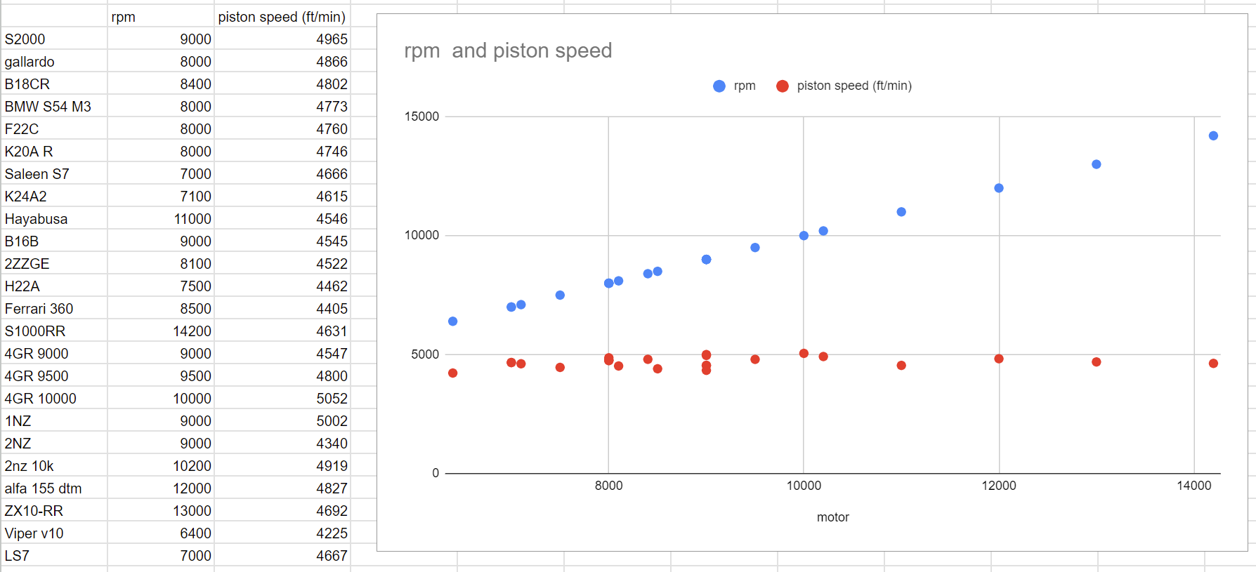
I had another good look over everything last night, and I couldnt see any issues. All of the piston pins move freely no problem. Even on the cylinder that went kaboom, the remaining end of the rod swings around on the crank no prob. No signs of any cracking or anything else on the remaining 3 that I can see. But yeah need a dye test to know for sure. And imagine what a pity it would have been if I listened to the formulas, and missed out on the most fun I've ever had in a car haha. There definitely does seem to be a sensible upper limit to mean piston speed though, even absolute screamers like the bike motors and Alfa DTM cars all seem to stay below 5K ft/min. Piston and rod weight will play some part, the fact that 1NZ rod and piston is so light is likely a big part of how it managed to go for so long without issues. So I might not be able to push the limit quite as much with the heavy stuff in the V6. A mate has a K24 that he's revving to 9k rpm - 99mm stroke so that's 5800 ft/min, bloody hell haha. Here's a pointless graph for you today @Stu
-
Yeah would need to use 3GR block, 2MZ crank and 2MZ rods. Or you'd end up with the piston sitting way too low in the block. Then you might get lucky and find that 3GR or 2MZ pistons work and give an acceptable CR. The 2MZ piston has a dome on the top, where as 3GR/4GR are dished with weird DI stuff on top of piston. So hopefully would be able to mill them down to a good CR if they are "too high" rather than the opposite. But who knows.
-
Dont you worry, I'll more than make up for it when the engine is running. Haha
-
So even more stuff matches up. Both have: 22m gudgeon pin 56mm bigend 61mm main journal. Welllll shit. Thats another item on my pickapart quest list then. 2mz guts!
- 653 replies
-
- 16
-
-
The 5GR motor has been brought up a few times in this chat - the unobtanium China only 2500cc short stroke GR motor. Well ive found out some interesting stuff. The GR series of motors shares a considerable amount of dimensions with the previous MZ v6s. They have identical bore spacing, bore offset, and stroke length between various versions of each. This would solve the mystery of where the 5GR crank comes from - Its a bunch of left over 2MZ cranks shipped to China to build cheaper 2500cc non DI GR engines with 3GR blocks. It would also make sense for why it was a 2005 year only engine -just an end of line bitsa, as the 2MZ cranks would be the only ones left unused by the GR series. 3gr bore x stroke: 87.5 x 83 1mz bore x stroke: 87.5 x 83 5gr bore x stroke: 87.5 x 69.2 2mz bore x stroke: 87.5 x 69.2 1mz cyl spacing: 105.5mm 2gr / 3gr / 4gr cyl spacing: 105.5mm If this is true. Then the ultimate combo would be a 3GR block (cheap and easy to get in NZ) and a 2MZ crank which I could likely find at pickapart or just buy a motor. This wouldnt exceed 5000ft/min piston speed until a smidge past 11k rpm. So this might be version 2.0 motor one day if that works.
- 653 replies
-
- 21
-
-
-
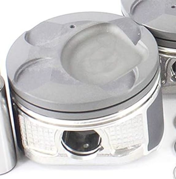
What is also cool, is that someone asked me if I could send them a file for the ITB adapter. Sure. So they had some CNCd And they've also made some 14.9:1 pistons. How good! And this is all going in a tube framed EP80 time attack car for a European hillclimb or autocross or something series. It still looks like cams are the bottleneck though, but it will be interesting to see how it goes with the higher CR and presumably some race gas.
- 1536 replies
-
- 23
-
-
-
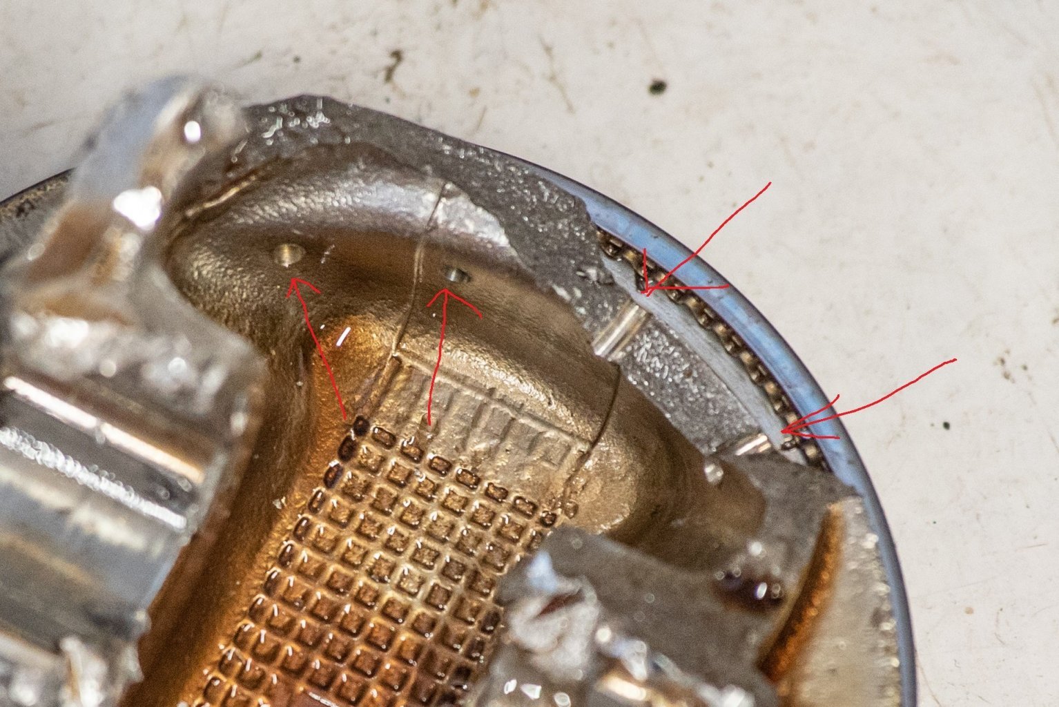
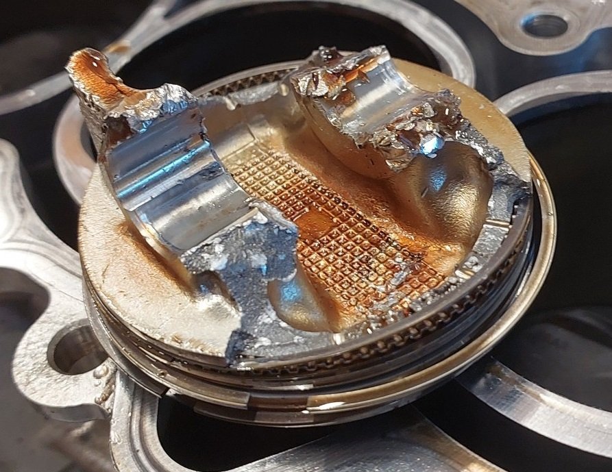
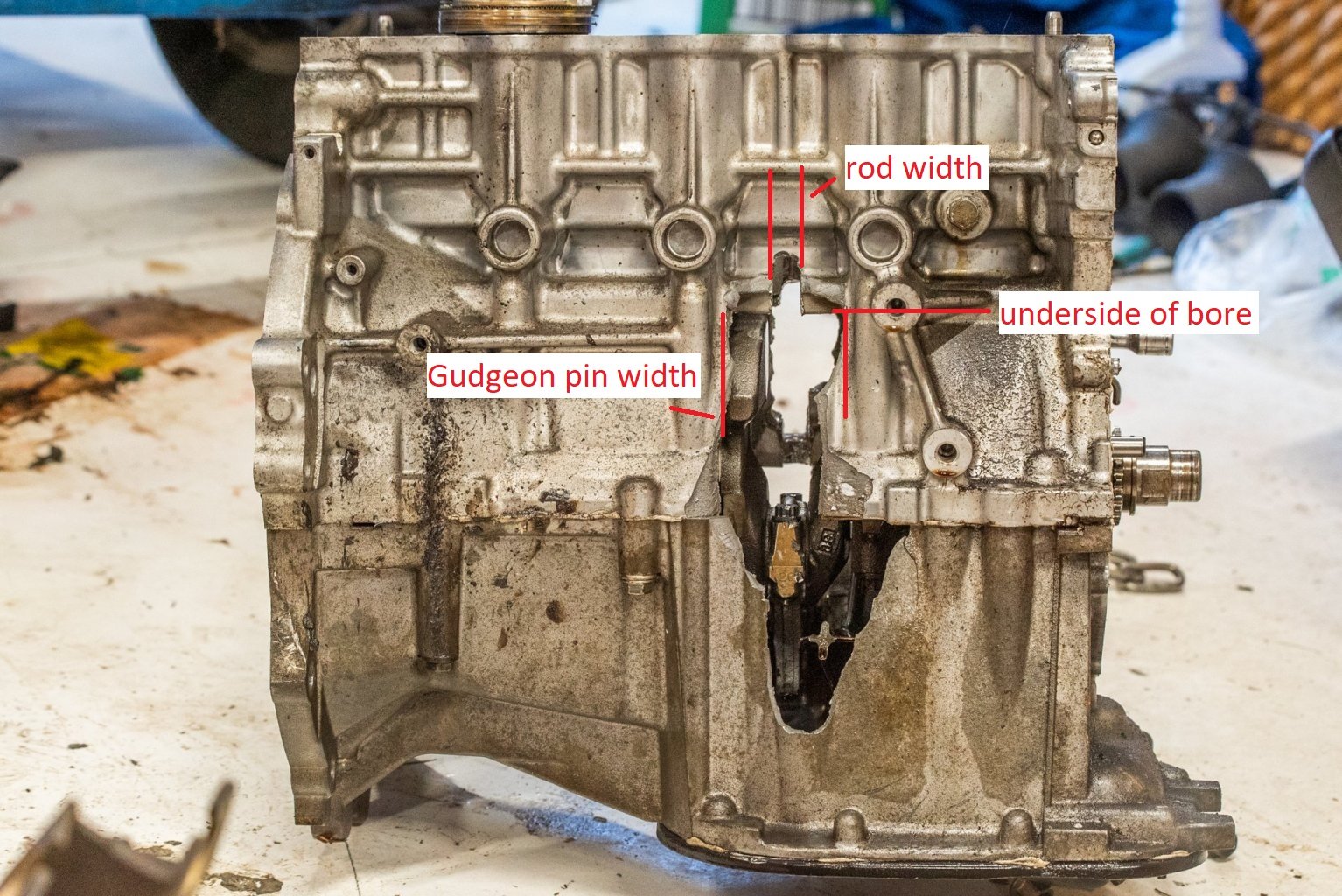
Hi, just a thread ressurection to cover off a bit of a post mortem on the first motor. I covered some of this earlier but I finally pulled the motor fully apart a couple of days ago. (FYI @GregT and @VitesseEFI ) So what do we know for starters before I pulled the motor out? Well, theres a big hole in the block. But unknown level of carnage inside apart from that a rod is broken. So my first thoughts were, yep, finally the skinny 1NZ rods have caught up with me. Which is why I had some forged rods set aside for fitting at some point. However, when I took the head off the engine. It was interesting that on this cylinder the piston was just parked at TDC. It hadnt hit the head at all - no damaged valves or anything. The only damage was some block debris that got sucked into an adjacent cylinder, and put a little dent in the piston top. So I was expecting to pull out the whole piston, with a little bit of rod dangling off the bottom. So when I tapped it out, and this is all that came out, I actually laughed so hard. Oh man! Totally unexpected! Then looking down the bore, there was just a small part of the rod left swinging around on the crank. Gudgeon pin AWOL but possibly in the sump. Oil filter and housing both AWOL. So some of this isnt consistent with idea of the rod breaking first. For starters, if the rod broke first I'd expect to see the gudgeon pin and a small part of the rod still hanging from the piston. Looking at the piston there are two types of damage, some areas where they have been bashed by the rod or gudgeon pin. Where it looks dented in. But then other areas where it looks powdery - this is cast alloy breaking or being pulled in half. Then looking at the block, there are some clues about what happened too. Since the piston was just happily parked at TDC it makes me think that what likely happened is this: Piston approaching TDC, decelerating. Rod starts yanking the piston back down. Piston says "no thanks" piston cracks, top stays at the top held there by the rings. Now the lower half of piston, full rod, and gudgeon pin are swinging around unsupported. On one side of the block, you can see where there is a notch that clearly shows the width of the rod flapping around smashing stuff... But a little bit below this, is a hole a little wider than the gudgeon pin... So I think the unsupported rod flopped over, got pushed hard against the bottom of the sleeve/bore. Then the only direction it could go was out the side. Then it had no choice but to smash through the block. Then either on the way out or the way back in, the gudgeon pin and top of the rod broke off. Then the remainder of the rod was free to flail around, which is why there's a vertical notch higher than the wide gudgeon pin sized hole. The piston has holes in it to return oil from the bore that the rings scrape off. So these were a weak point, broke partially across these. Being a 4 stroke engine there are two times approaching TDC where this could have happened, on the compression stroke or exhaust stroke. Can we tell which? Well, can have a good guess. When you do a compression test, you might get like 200psi or 150psi on the gauge... thats a value from the compression stroke. So on the compression stroke at TDC it's actually holding the top of the piston in place with 200psi or whatever before any combustion has happened. Then also since you have an ignition event happening earlier than TDC, it's already building some pressure from that too. So unlikely to happen on this stroke. On the exhaust stroke though, especially if you have good extractors. There is no ignition event building pressure. The only resistance on the way up, is the exhaust gas trying to push out the exhaust. At or close to TDC there can be close to absolute vacuum above the piston. So you've got 200psi less force trying to stop the top of the piston from coming off. So this makes me think it likely happened just after TDC on exhaust stroke. When I pulled all of the pistons and rods out, there wasnt really any extra information to be gained about the one that was damaged. But I thought it would be interesting to look at the other three. I've not measured anything up, or pulled anything apart. But a visual inspection doesnt show anything immediately wrong with the other three. 1NZ motor still makes me amazed at how tiny everything is - Undo the rod caps with a 10mm socket. Undo the main caps with a 12mm socket. Haha! Which is not saying something against it. This is the whole reason this motor went as well as it did. Everything is CRAZY light. Nothing is bigger than it needs to be. And the end of the rods have small dowel pins in them to align the cap as well. Real race car shit. The main point of trying to figure all of this out though. Is that if the piston failed first, then there's no point fitting aftermarket rods (which I already had) So in that respect it was disappointing to see that the piston seems to be what broke. As aftermarket pistons cost a lot. I'm not sure if there's too much more I can discern from these remaining pistons/rods as I dont have any decent measuring equipment etc. However it might be interesting to do a dye penetrant test on a piston and see if there's any hairline fractures etc. I'll buy a kit at some stage, and post up if there's anything interesting showing up.
- 1536 replies
-
- 30
-
-
-
Yeah they do make roll cages out of it. I'm not sure to be honest, I've just heard it tends to crack or shrink a lot from welding and it causes issues. Since this is a flywheel that if all goes to plan it is going to be spinning at a fairly silly rpm. I'd rather not take too many chances with it. Buuuuttt yeah maybe I should have an ask around. I might go get a second flex plate/ring gear from pickapart and just bolt all that up. At least that way I can know if the motor can crank over or not.
-
Its damaged the back face that mates up to the crank. Its just dug one side a bit too deep.
-
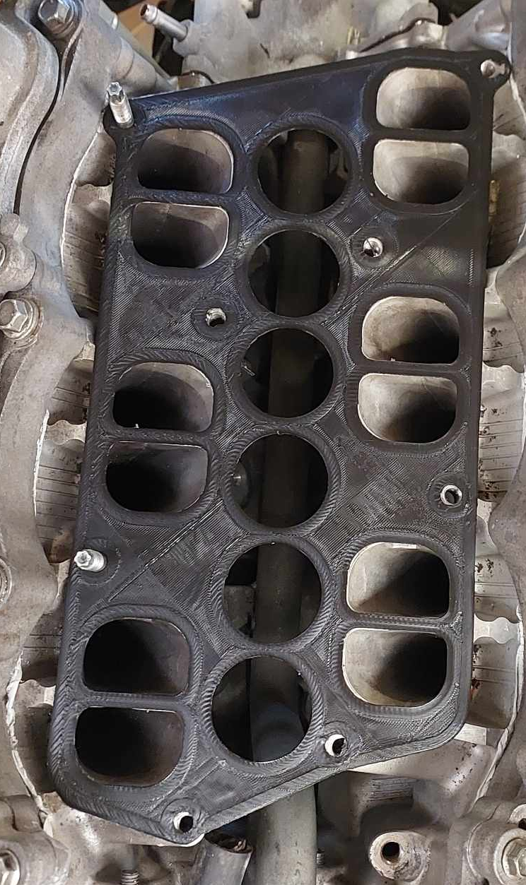
Rethinking my throttle situation a bit more. My e-throttle ITB setup on the echo worked well with a printed manifold, because the throttles were a single solid assembly. So there was no force applied to the manifold apart from the hanging weight. For the BMW throttles it is back to a two bolt flange on each throttle, and each throttle trying to twist itself off in various ways like the 20v throttles do. Also, it's very important that I have each bank of throttles perfectly(ish) aligned. So it seemed like life was unnecessarily hard having 2 separate manifolds. So I printed a big single one as a test fit to see how far off I was... the port spacing was about spot on, but a few of the bolt holes needed moving slightly. So I started from nearly scratch again, modelling a big slab looking thing. The idea is that it will have a layer or three of carbon flat over the top, and the bottom. So I wont try carve out the shape at all, simple is better. I've cut some channels into the underside, that will link all of the throttles together. A layer of carbon will seal this all off. Then I will tap into it for brake booster / IACV / PCV / whatever. So all that messy stuff will be tucked up nicely on the underside and come out the back. I'm gonna use recessed M8 cap screws to bolt it down to the heads, as bolts end up too close to the throttles. Hopefully this ends up strong enough to work as a printed part, and easy enough to make. Even if I do end up wanting to make a final part from alloy, it's good to have a reasonable scheme for making prototypes. This will be too expensive to get printed on the MJF machine via 3rd party though. Maybe for a final one. Another benefit of this is that I dont need everything bolted onto the motor to figure out the linkages, can work on it on the bench. The total assembly height is only 35mm though, so it would be feasible to cut most of this out of a big slab like my sump. So this might be a project for Dad's CNC one day. But the port geometry is very difficult, would need hand finishing as you cant reach a lot of the areas with a 4 axis machine. If I do that, I'll cut the shape down to just have a lot of ribs between throttles and remove most of the material, as it would weigh heaps like this. It looks like my flywheel got damaged beyond repair when the cutting tool caught it in the mill. My understanding is you cant really weld chromoly safely so dont think it can be built up with material then skimmed flat again. So will have to look at other options again. It might be feasible to skim it down further, skim all of the outer part off beyond what the clutch plate needs. Then run a standard flex plate behind it. No stress though, shit happens - chalk it up to the learning budget.
- 77 replies
-
- 24
-
-
-

sheepers MS51 of hyperbolic enlightenment and anomalies
Roman replied to QCADTA's topic in Project Discussion
Oil squirters Here's my thoughts - if they werent there, dont go out of your way to fit them. If they are, then sweet. The 3 Banger GR yaris motor has 3 under piston oil squirters per cylinder. And each piston of that motor about the same power as 3 5M pistons, so the maths checks out! -
100% definitely watch this one, great vid @yoeddynz
-
You're right, it was a great video and I love the amount of effort he goes to on these vids. I think what I meant was that the first video felt like he was really onto something and had unlocked the secret to the cool sound. That we could all try apply to our engines... But then left a cliff hanger on the actual results. But then second video was more like deconstructing all of the reasons or theories for why all of the stuff from the first video didnt work. So was disappointing in that regard, but still awesome/funny content. However, there are still a few good datapoints for GR motors on what sounds good.
-
Ahhh pity that his V12 didnt end up sounding any good. Cool that he's working to still develop it though. That's the only way to make NA engines do what you want - by suffering. haha Video wasnt quite as a cool as the first one, but sometimes reality comes and punches your theory in the face haha. I saw another video on youtube where someone did a front facing 6-1 on the Honda J series V6. By my ear it didnt sound any better or different than the 3-2-1 setup. Maybe just when you have to make the pipes so damn long to make it work, it doesnt work anymore.
-
Oh shit! Been waiting for this vid to drop for ages. Watching now!