Roman
-
Posts
7,218 -
Joined
-
Last visited
-
Days Won
39
Everything posted by Roman
-
@thegreatestben From what I've seen they are largely based around fitting bike's available space. Notice the balance pipes though up near the flange. Seen this on a few bikes. On the S1000RR they have a throttle plate on the balance pipes, so they can open or shut depending on rpm, because it does (something something)
-
The V6 isnt like a V8 where the cylinders have uneven firing spacing on a bank. The only difference between 3 cyl and 4, is that the spacing is an even 240 degrees rather than an even 180 degrees. So presumably the scavenging effect just needs a longer pipe to acheive the same tuned rpm. I guess you could put a Y shaped section in the middle, to extend the merge like Rhys' example.
-
Cant find it. I suspect some kid grabbed it as a high tech souvenir, like they do at F1 car races
-
Oh wow. That actually looks pretty good, and would fit better! Anyone in Waikato got one spare?
-
Thanks though!
-
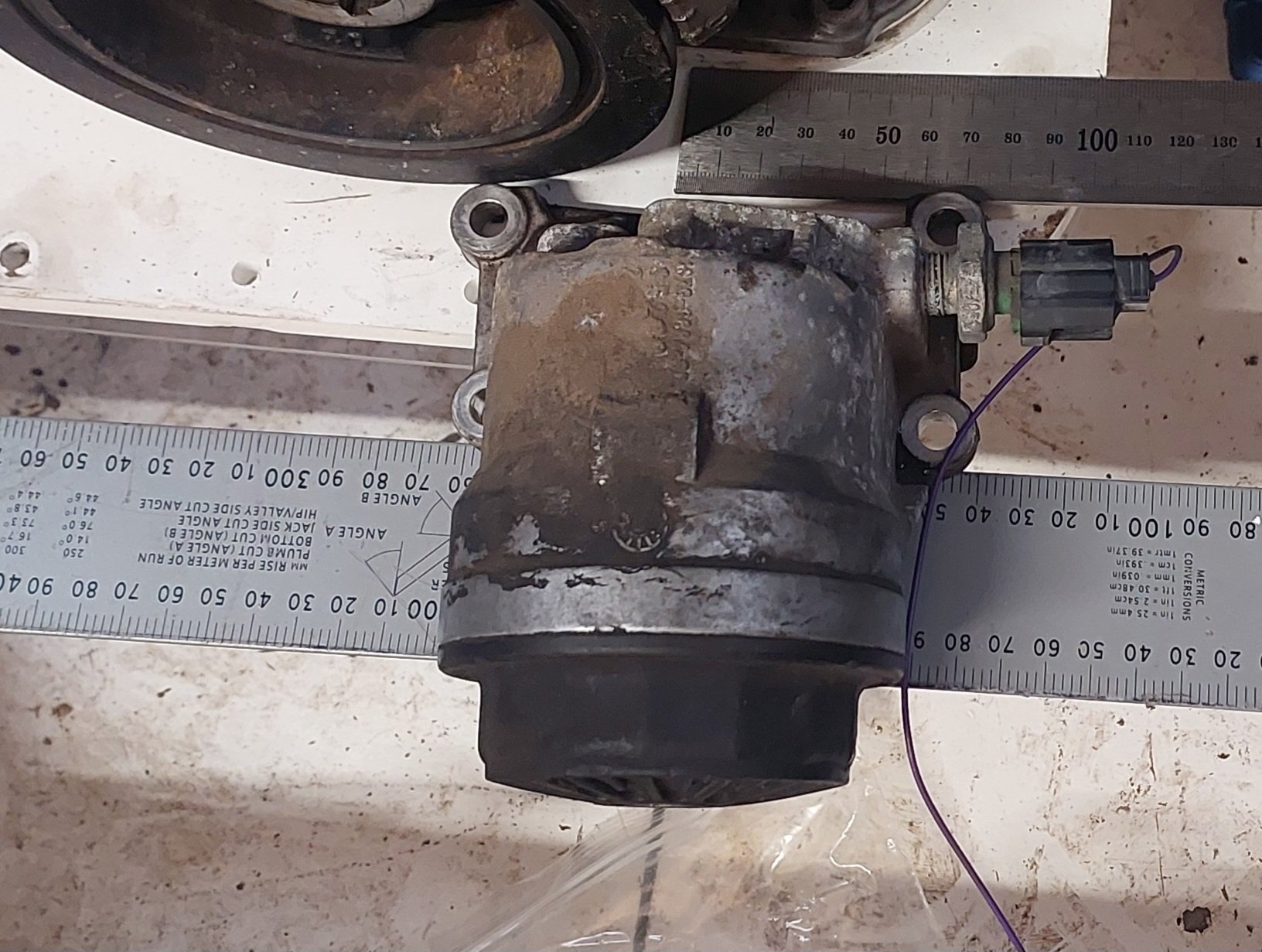
Found this on a Mazda 6. Not 100% cconvincedthe outlets are workable but will draw it up and see. might try get a mazda 3 one as well before i commit. As theyre only 11 bucks each.

-
Can prime it initially while the filter is off and syringe some oil down the inlet and outlet. But then after that it should hold all of the oil from the pump onwards when the motor is off.
-
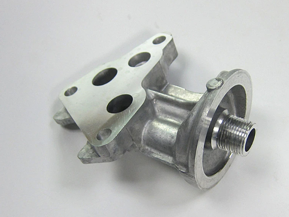
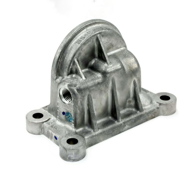
Alright I think I've nearly got a plan sorted. I remembered the 4WD 4GR which I saw at pickapart. It had an oil filter housing that bolted on, rather than cast as part of the sump. However it looks fugly and it's stupidly bulky: Doesnt look like a useful option. However, it got me thinking that maybe there's a better type of bolt on filter housing from something else. Scouring the internet relentlessly has lead me to the Mazda 3 filter housing. Looks bloody good! So hopefully I can have this sitting on top of the sump plate, by drilling holes like this. Hopefully the oil flow direction is the right way around. But eyeballing it I think it's gonna be backwards. pooz. There's another variation of Mazda 3/6/whatever filter housing that could be good too, looks like the lines run the other way. And it's got a thread for a pressure sensor or switch too. Might try find this one, if there's any at pickapart.
- 130 replies
-
- 23
-

-
Yeah metal 3d print is $$$$MegaNeds$$$. I could likely get something CNCd for cheaper. Yeah for a 4-1 I've thought about adding that plate in the middle @BiTurbo228 but it's pretty tricky for a 3-1. As with the 4-1, the benefit would come from using the plate to initially pair only 2 of the cyls together, and the other two. like this. With some fuckery you could probably get the change in cross sectional area to two fairly small bumps. However with 3-1 there's no way to divide them equally.
-

Discuss here about Yoeddynz's little Imp project...
Roman replied to yoeddynz's topic in Project Discussion
Go start some bush fires on Takaka hill with the Imp, then go put them out as the fire fighter. Full circle community swoon for Alex. -
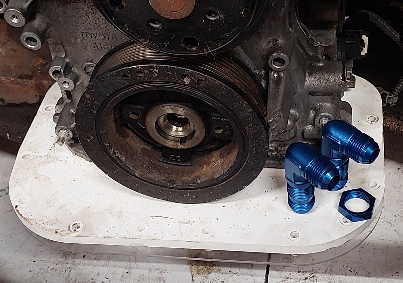
Ive got some dash 10 bulkhead fittings, could just have the nut do up from the bottom. Or have then upside down. Bit im thinking some type of shorter AN fitting that threads into the top of the pan probably the best. Then underneath just two pipes. Open to any suggestions. I think straight drill through the front would clash with the pulley or belt.
-
Thanks @Rhyscar could be keen to borrow that some time.
-
It can go anywhere, its just if i were to internally drill from the front then thats how it needs to go. Im leaning towards a small pair of 180 deg pipes inside rather than drilling from the front. So fittings thread in from the top.
-
Yeah i thought of that. But too much of a pain. Although probably not an issue if the engine wont last the length of an oil change interval
-
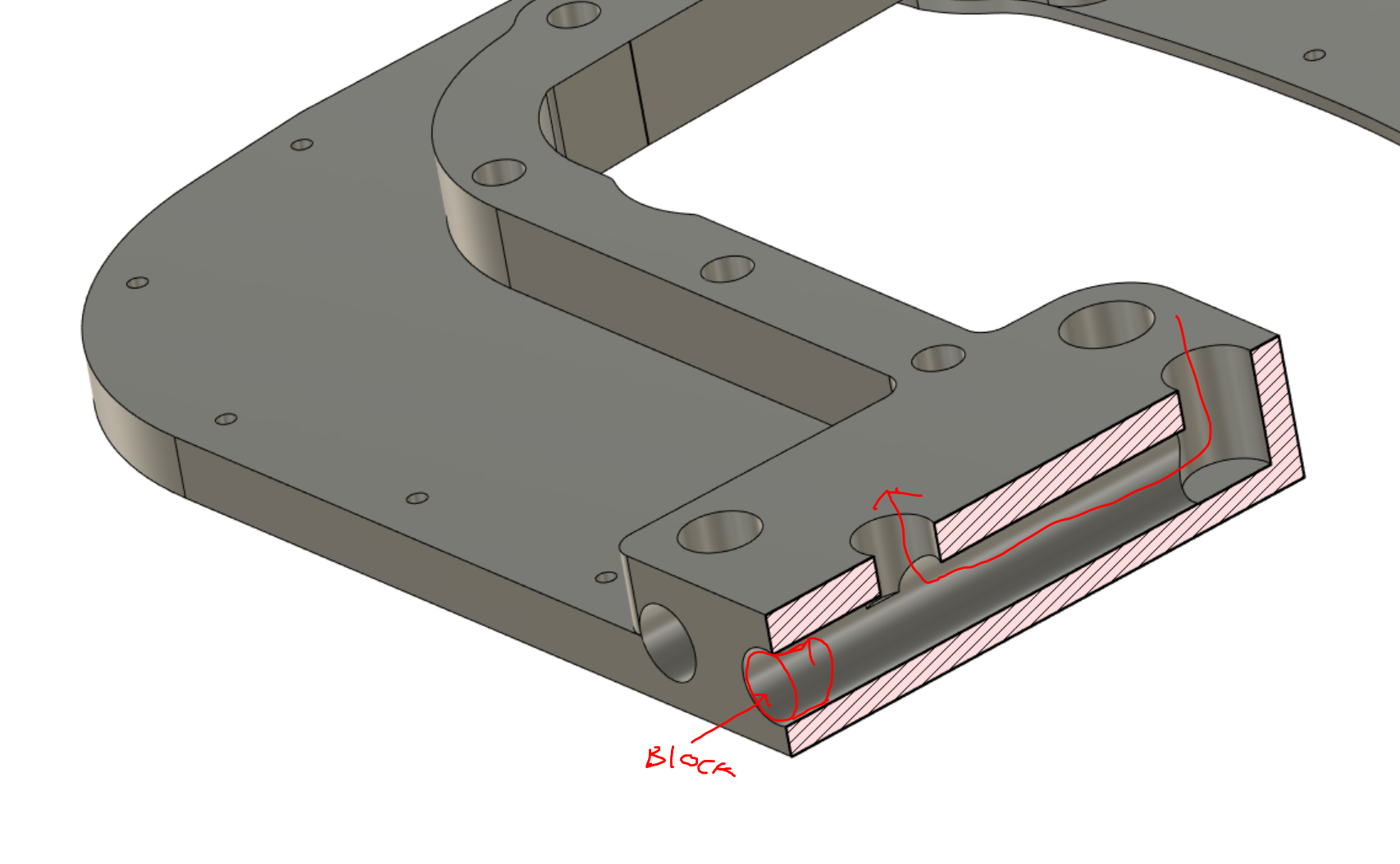
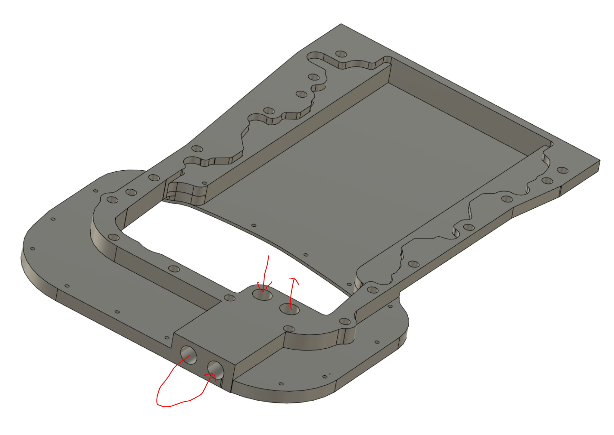
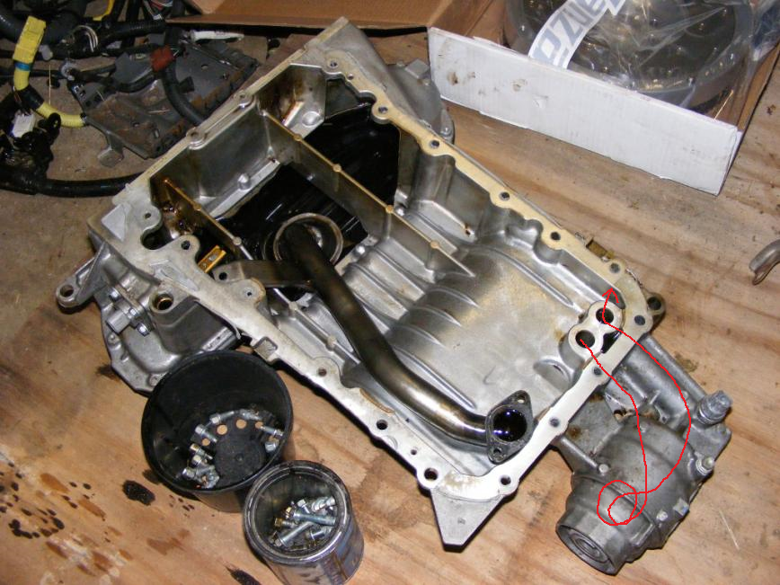
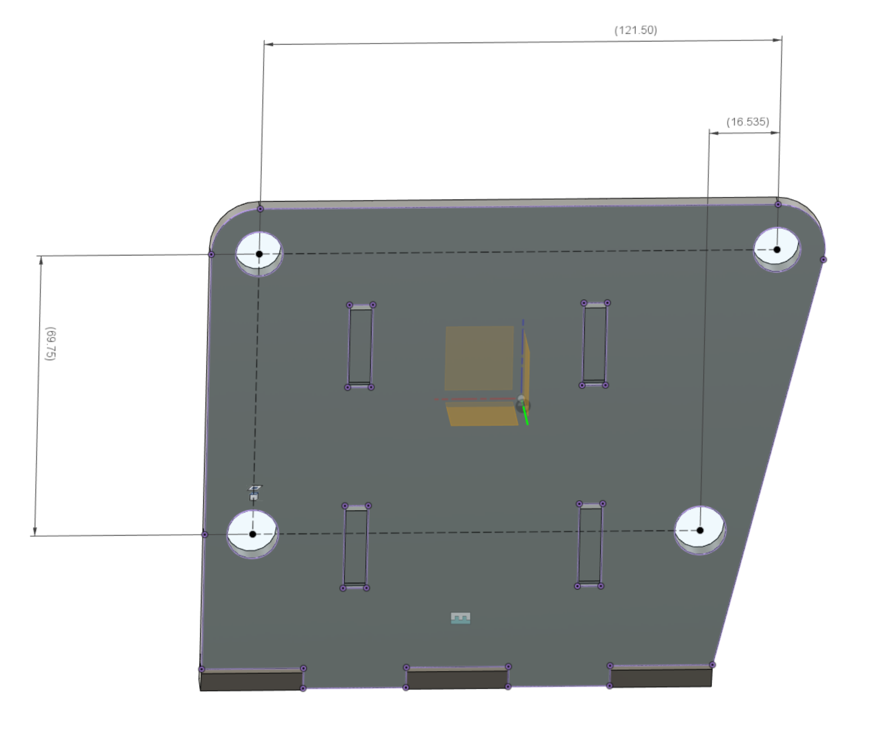
Another sidetrack - back to the sump. Looks like will try machine it entirely out of a single 32mm plate, as 25mm wasnt going to be quite enough. This might help solve my oil filter situation. On the bottom of the front timing cover is the outlet of the oil pump, which feeds down into the sump for the oil filter, then goes back into the sump, back up into the front timing cover. I've been tossing around a few ideas for how to address this, maybe running some internal AN lines or a welded in pipe that does a U turn so I can have some AN fittings come out on the top face of the pan. Then run a remote filter. However since it will all be a single piece now, maybe it can be drilled like this so it comes out the front. Or, drilled but then a plug screwed in, and other holes drilled on top so the fittings face upwards. Will need to see what sort of clearance I've got to the swaybar in this area. Poking out the front might not work. I might also not have enough clearance to the front pulley for this to work. Anyone else got any good ideas for how to address this, that I might not have thought of? Sometimes when staring at the same model for so long, there are some obvious ideas smacking you in the face that you cant see. The factory sump does it like this. EDIT: Gosh I could tap that line for the oil pressure sensor as well, like factory one does. Sweet.
- 130 replies
-
- 22
-
-
Discuss here about Yoeddynz's little Imp project...
Roman replied to yoeddynz's topic in Project Discussion
Man your workshop is just a work of art in itself. Good to see progress coming along! -
It certainly does package nicely that way, if it's got enough travel. Which I'm sure it would. I've not seen this thread pop up for ages, and wow you've been doing some real cool stuff. Look forward to seeing how it all comes together.
-
Sure. They're different left to right. This is the drivers side of the block, looking at the face that bolts to the block. Then this is the passenger side, looking at the face that bolts to the block.
-
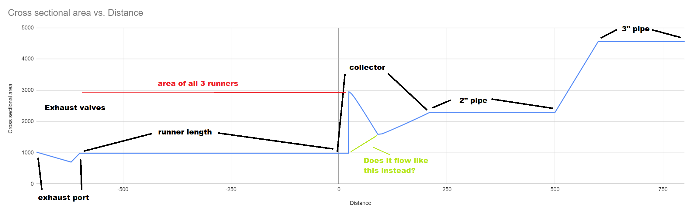
Completely off topic to anything and possibly not useful information. (Since when has that ever stopped me) I measured the cross sectional area of the collector at a whole lot of points through it. Then added cross sectional area of other known bits to show a map of whole exhaust. The cross sectional area stays exactly the same as the runner until a point where it near instantly blows up to the cross section of all 3 pipes. Then tapers down from there, then flares up again. The point in the collector where there's the big spike upwards, is here. It seems you cant do much to change how big or quick that spike is, except for by merging more cyls together or vice versa. However changing the collector angle changes how quickly it ramps back down to normal cross sectional area. I found a picture of the Alfa 155 DTM engine / it's exhaust manifolds. Doesnt look like anything especially magical going on there. Beefy diameter runners though Runner lengths seem fairly long considering it's a 14,000rpm motor. Meaning way longer than that is probably good for mine.
-
Yeah i will definitely have the pipes merge before any mufflers etc. Try get the higher pitched sound from it. Im not really sure what length to aim for, for the 3-1s. Can go as long as I like really. Current length with no collector was 640mm give or take. Ive got heaps of room once im past the steering column. Since theres only 3 exhaust events instead of 4, id expect a longer pipe needed for same tuned length compared to a 4 cyl. Unless the scavenging effect is each runner scavenging itself. In which case the same length. That noise from the car above does absolutely nothing for me. Ive never been huge on v6s. Buuutttt throw some doorty intake noises into the mix and its acceptable, even with pooey rpm limit: https://youtu.be/1zQAPDmGZrg With a few thousand more rpm than that, now were getting somewhere!
-
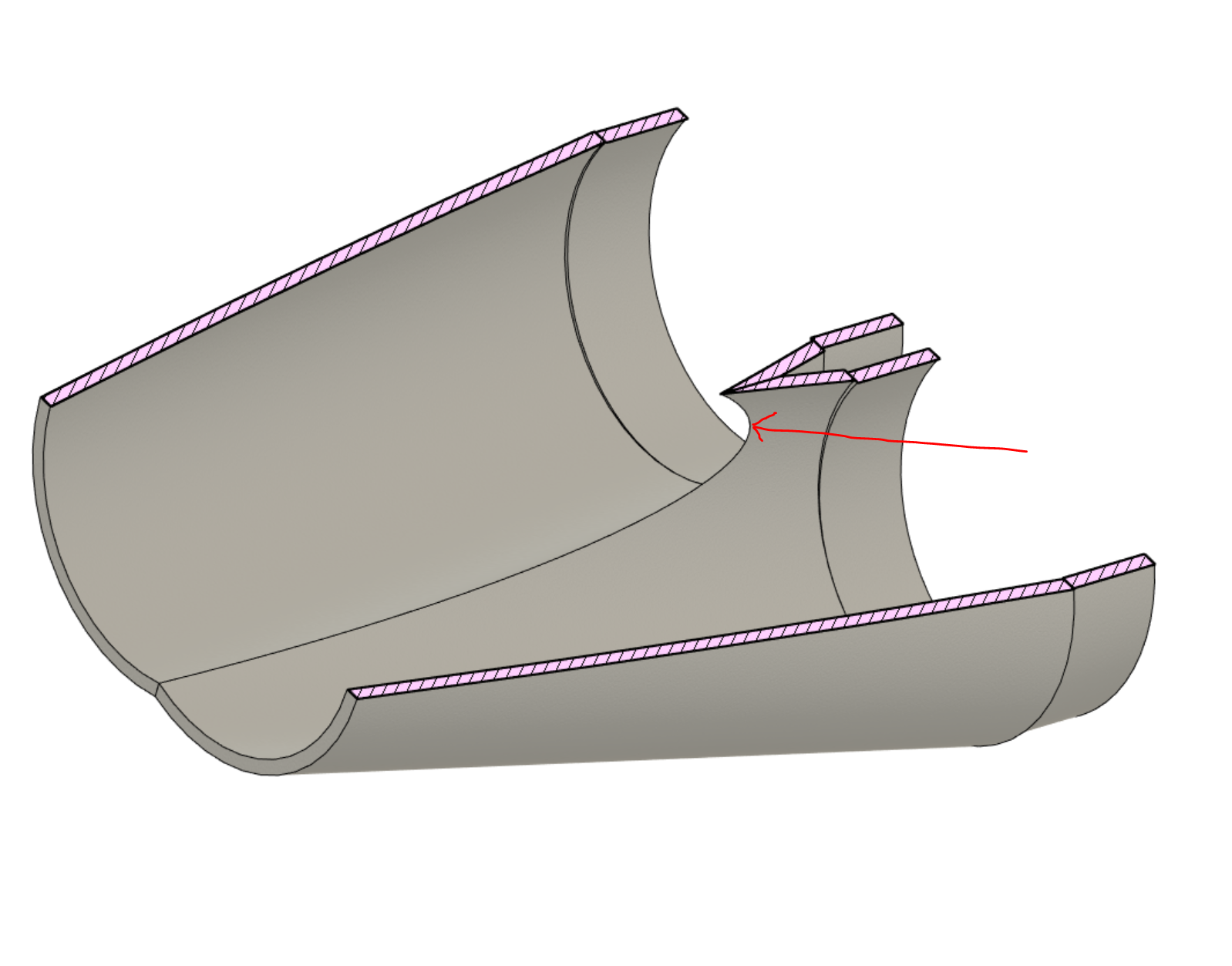
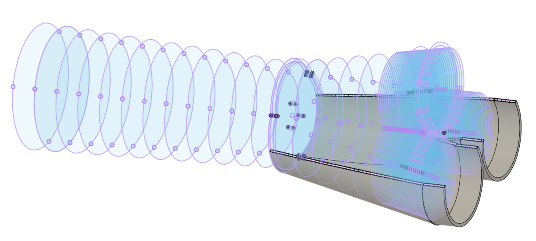
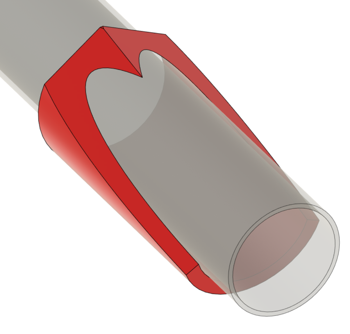
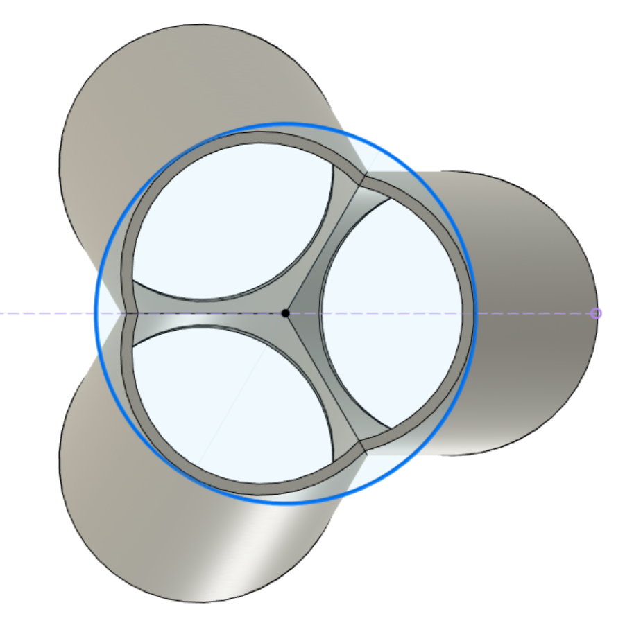
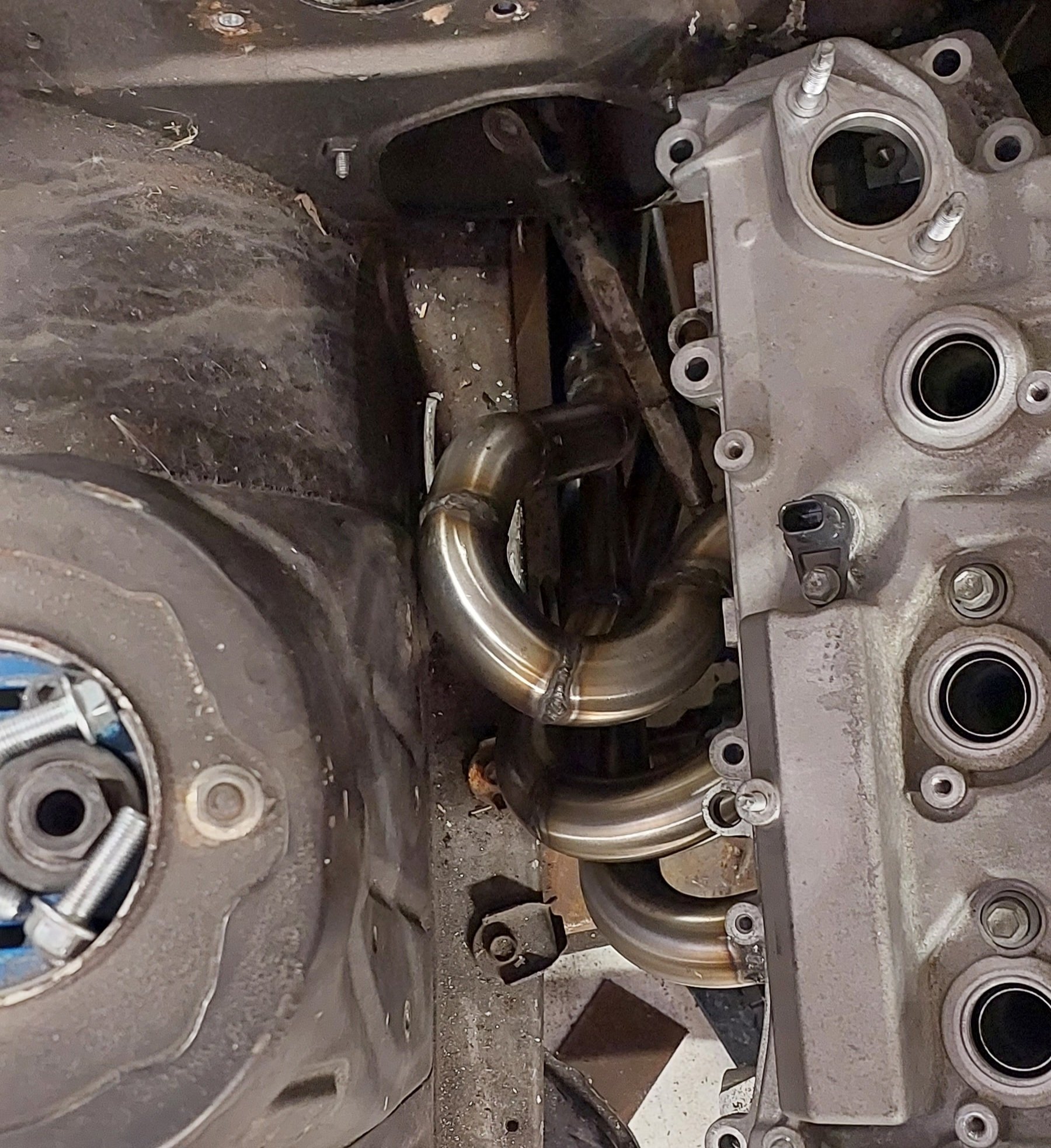
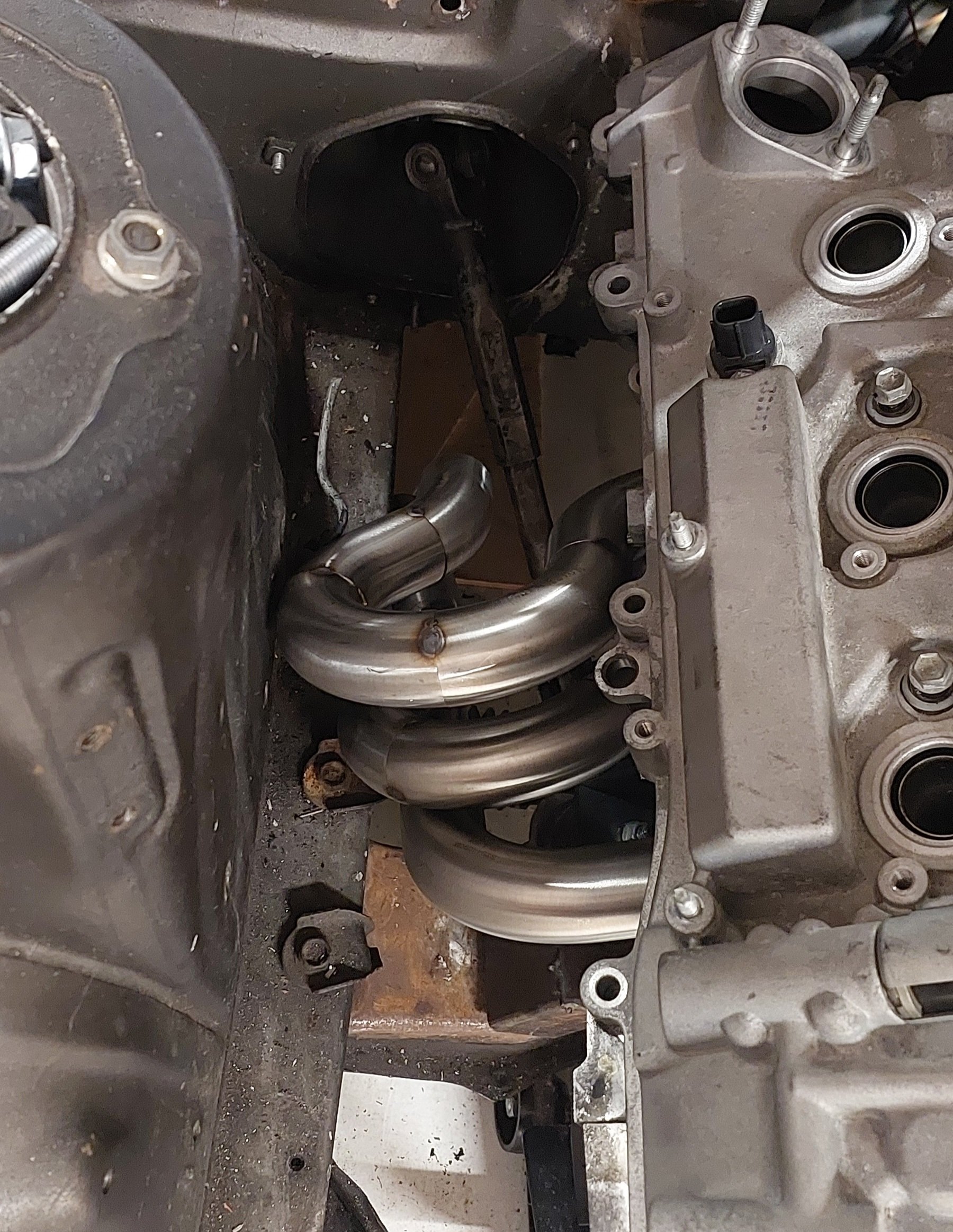
Alright sooooo. It's been a case of: tack pipes. test fit. cut pipes back off. test fit. tack pipes again. scratch head. And so on, for about 30 iterations until I've run out of bends and argon. However I've now got something that clears everything. Doing some checks on lengths, they're within about 40mm of each other. Which is about 5% variation - happy with that. However, a few problems. Firstly, I've chopped and changed everything so much that it's a bit of a mess. Partially due to being short on patience from redoing everything a lot, and not having totally flush surfaces. So welds turned out more pooey than needed. I should invest in a linisher I think. Secondly, This is all great that everything's past the steering column, and 10+ mm clearance to everything. However everything is on some tricky angles to try stuff into a collector. I havent made a collector, because it seems hard. Or I need to buy some. The only purchasable collectors that fit my budget look like baked bean tins that have been stood on. So I will try make something instead. As I think what I really need to do. Is to start the pipes from the collector, then work back towards the head from there. Welding a collector is tricky, because you end up with a bit in the middle that you cant reach to weld when it's together. One way is to cluster the pipes together tight. Then weld a little triangle piece in the middle before it goes together, on the collector and 3 pipes. Then weld the remaining perimeter to finish it. (Idea stolen from @kpr - thank you) So hopefully something like this. To choose where to slice the bottom part, I've drawn a circle the size of a 2" pipe, then just cut it shorter till it roughly matches this. I could go bigger or smaller though I guess? Currently has inside area equivilent to a 1.75" circle. My plan is to print some cutting templates like this. If I had a band saw I'd do it a little differently so the outsides are flat so it sits on the right angle on the table. Actually - yeah might do this and see if I can use bandsaw at dads. Assuming it's happy cutting stainless. Fingers crossed it works out alright. Something else to think about. As per oldschool.co.ng project tradition, 3" exhaust pipe. However - I've got two banks that need to eventually merge into a single 3" pipe. I'm not sure if there's any useful tuned stuff happening in the 2-1 part of a 6-2-1 setup. If I was trying to keep the "secondary" pipes to half the cross sectional area of a 3" pipe, then it's about 2.1" per side. I definitely want to merge all 6 pipes, because otherwise it'll sound like I've got a pair of triumph motorbikes in the engine bay rather than a 6 cyl.
- 130 replies
-
- 24
-
-
Yeah ive had it in and out now a bunch of times while trying to make it fit better. Doesnt need to lift up very high. Probably wont need to on the other side where theres no steering column. I can live with that! Ive now got something that has pretty good clearance everywhere. But ive chopped and changed this a million times so its a bit of a mess. So I might redo it with some fresh bits when funds allow. Has been sort of fun and sort of frustrating. My plan to keep all the runners on a flat plane went right out the window. Just not enough space to the strut tower and chassis rail. I think i will restart with a different approach. Start at the collector end and work back to the motor. These are within 40mm of each other though which is pretty sweet. (So around 5% variation in length)
-
Weerg.com
-
Started pooing together a manifold. Too tight damnit. Will have to tighten the bends a bit with a few angled cuts. Also, the only way I will ever get these off or on is by lifting the motor. And all of the studs in the head need to come out or its impossible. A bit of a hassle but better than having the shitty standard log manifolds.
- 130 replies
-
- 34
-
-
Aircraft people do weird shit with running their engines. My understanding is they adjust the mixture to peak EGT then back it off 10% richer (or something like that) Or some other witchcraft sorta stuff depending on if they are wanting best economy or power when running the motor in steady state slogging its guts out. So in that case the reaction speed of an EGT sensor isnt an issue - they arent really in closed loop. Just using temps to manually trim the fuel. (At least that's my understanding) So for the purposes of what they're doing, ignition timing is essentially fixed. As the motor is at steady state. By contrast the operation of a car engine is absolutely chaotic. With rpm changes, ignition changes, fuel changes happening constantly. Which is probably why they're not commonly used for cars.