
- Popular Post


yoeddynz
-
Posts
17498 -
Joined
-
Last visited
-
Days Won
136
Posts posted by yoeddynz
-
-
Picking myself up now.
-
 1
1
-
 4
4
-
-
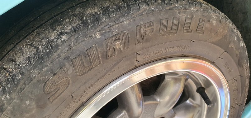
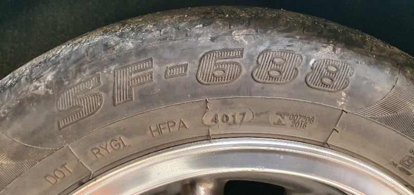
I bought some Sunfull 688 175/60 13 for the imp @ $60 each fitted and they've been great. Very grippy, pretty quiet and seem to be wearing well given my lowered imps alignment, how its often driven. I do rotate them back to front as the fronts are scrubbing off the outsides. Theyve done 12000km so far and if the alignment was better they'd be fine for more.
Actually genuinely happy with them and will get more if available. They have had good reviews overseas too.

-
3
-
-
On 18/01/2024 at 20:51, KKtrips said:
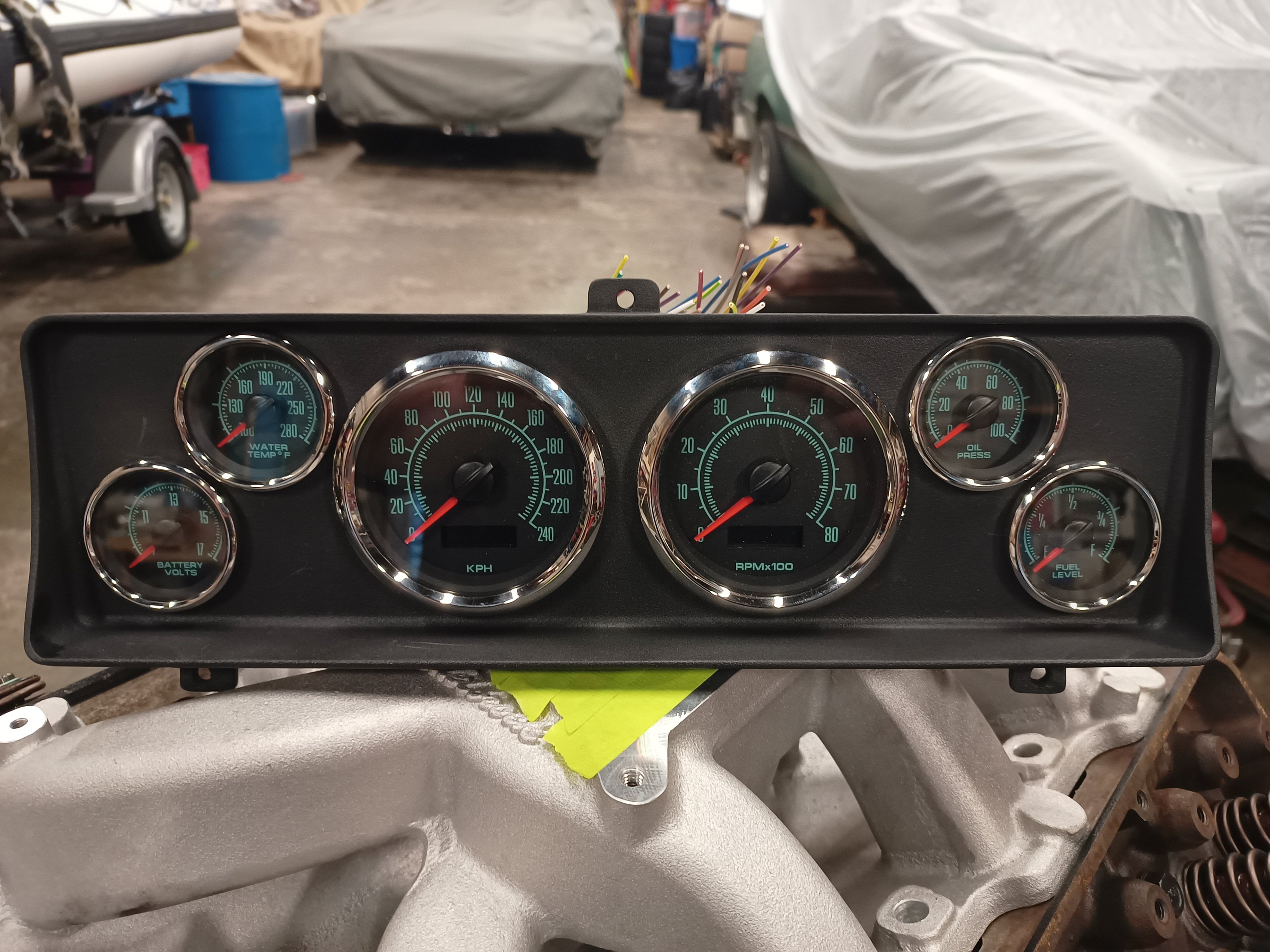
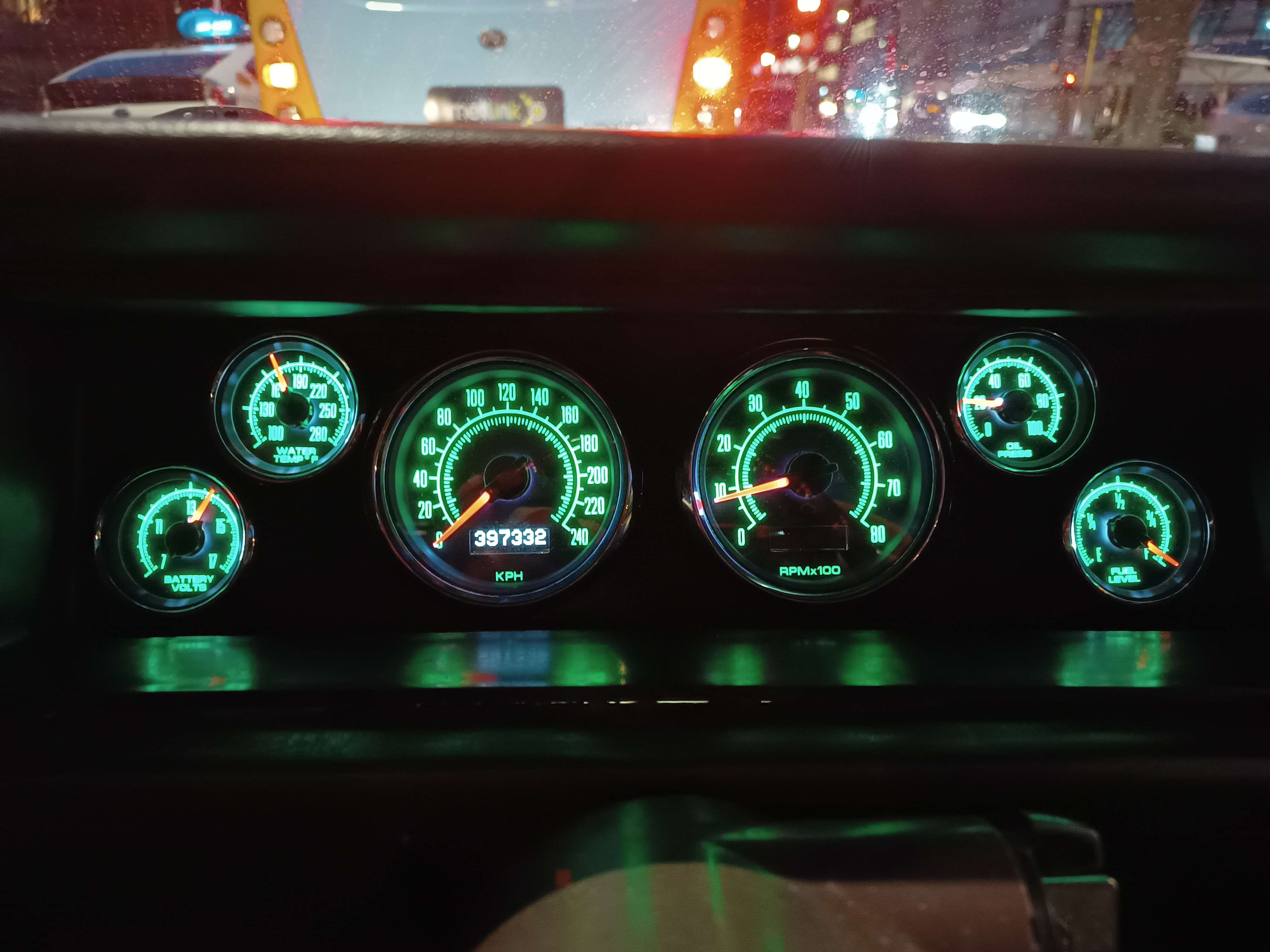
Yeah the ones I used are pretty sweet, they have all the idiot lights incorporated into the gauges, which really looks good. They also wire up really nicely too.

I want to re-do the imp dash in the future and like that style. How much did that lot cost? (guessing I will probably need to sit down)
-
1
-
-
and a yellow car too!
-
1
-
-
You're almost there. Just needs more kitten content.
-
 1
1
-
-
- Popular Post
- Popular Post
-
18
-
There was once a fella called @dattochriswagon who had a datto wagon with grand plans.
Then he didn't.
I wonder if he's got kittens?
-
- Popular Post
- Popular Post
Looking forward to seeing the kittens that @Bart's Handbrake is promising. What colour will they be? Fluffy?
Such excite.
-
5
-
1
-
5
-
Oh cool- I'd love to see pics of such conversion. I think the covair motor is also a anti-clockwise rotating engine so I'm guessing they used the covair transmission too?
-
As soon as you said andrew, s660, I thought I know who that is. Lovely chap. Likes waterfalls so we showed him one...
-
3
-
-
The citreon ami is one that springs to mind as being ideal for nz towns and cities.
https://www.citroen.co.nz/about-citroen/concept-cars/ami-one-concept.html
-
4
-
-
11 hours ago, shrike said:
It's just swap the (sorry if wrong terminology) ring gear on the diff so it runs in reverse yeah? Or the carrier?
Any gearbox tweaks for dual spinning or anything like that?
It's all in the build thread in great detail. Too much to type here.

-
1
-
-
The way that sits on little wheels * is just so perfect. One of my favs ever.
*stance is what the kids call it I think.
-
2
-
1
-
-
Yeah I'd honestly be happy if its still got 100bhp at the crank. Its that 110lbft of torques I'm interested in and really the whole thing is more about the sounds and look of the setup. 5 speed box and higher diff will be an added bonus so long as it doesn't spit the dummy being used in reverse.
Putting the box back together is the next job after this cooling check and tune.
-
4
-
-
- Popular Post
Once again thanks so much fellas. I'm still beaming from ear to ear and looking forward to the next stages now I know it works.
When it was running and I gave it a little prod of the throttle it revved so quick to 3800 (it has no clutch installed so a very light flywheel right now) , it sounded so eager and angry. One of my thoughts was 'shit... I'm really going to have to make sure the driveshaft modifications are solid as fuck'
")
-
13
-
7 hours ago, shrike said:
Do I need to crank my speakers or is it quiet? Great sound either way keen to hear it scream
Crank your speakers. I think my phone struggled with the background noise from the silly loud cicadas we have here.
-
55 minutes ago, RUNAMUCK said:
Damn those cicadas are loud up here eh!
Fuck aint they just. Its a good cicada year this one. Heaps of them... trying to muffle out the sound of the flat six
17 minutes ago, Vintage Grumble said:It sounds sooooo damn good!
Doesn't just! I'm already thinking my muffler design is going to be minimal to start with..
") I'm looking forward to getting the coolant in and tuning it so I can really get the idle down because I can already tell its going to have a really sweet idle sound.
1 hour ago, NickJ said:
I'm looking forward to getting the coolant in and tuning it so I can really get the idle down because I can already tell its going to have a really sweet idle sound.
1 hour ago, NickJ said:... just another weekend away from finished right?
Totally. Pretty much drop it in, wire up the mandolarian spaceship lights and its good to go.
-
3
-
-
- Popular Post
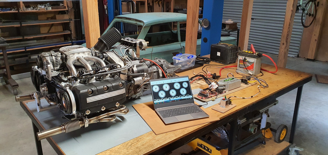
Bench testing continued.
The sump was now holding oil. Phew. I fitted the old smiths mechanical oil pressure gauge that was originally fitted in the imp race car. I mounted the gauge to the temporary coil stand. With the engine cranking over it was seeing about 20 psi. The oil level would drop in the sight glass and after a minute or two it would be back to the old level. I was happy with this.
Next on the list was to check the idle control valve was working. Its a 2 wire Bosch style pwm type unit. Very common, simple, reliable and hence used often in megasquirt installs. Its basically a rotary valve that is opened against spring pressure by a solenoid windings when current passes through them. The ecu earths its ground wire in a series of pulses, the quicker the pulses the more it stays 'open'. Simple as I thought.. but.. this is where I discovered that I had bought one of the units that is actually 'closed' at about 30% duty cycle. A failsafe on cars that use these for closed loop idle control (aircon/powersteering/epic sound systems etc etc) If the valve fails then spring pressure actually takes it to a slightly open state so the car cant stall.
But I'm only using the valve for open loop at start up. So when its closed I want it to be closed. Luckily I was able to pick out/burn/pick out/burn/pick out the tough as epoxy that was holding the valve stop adjustment screw in place. I wound the screw in until the valve was closed with no power. It still passes a tiny amount of air but its much better. I'll manually adjust the idle bleed screw on the throttle body to get the fully warmed up idle where I want it when that time comes.
Which was going to be soon I thought! Next thing to check was that the crank angle trigger wheel VR sensor and the camshaft half moon hall sensor were both putting out satisfactory signals. Opened up the composite logger on tunerstudio expecting to see nice clean signals.
But there was nothing. My heart sank. Oh here we go..
I took off the cover on the main board plug and checked the connections there. I then popped the volt meter, set at AC volts, onto pin 1 and 24, wound the engine over and got about 2.0 volts.
I don't have an osillioscope and only have an old megastim 2.2 testing unit which won't create the required rpm signals I needed for testing.
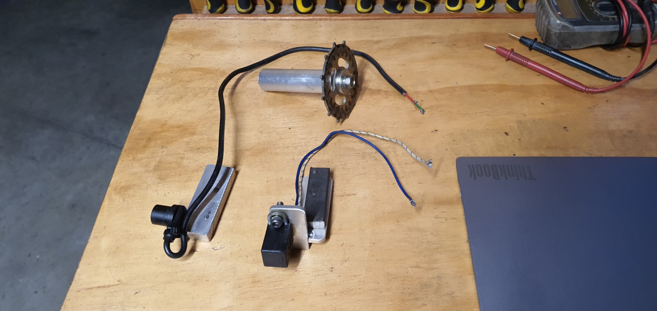
I wasn't quite sure what to check next so I started a thread on the megasquirt forum. Got some bits of advice but in the end I rang a mate in Richmond who has a lot more knowledge with megasquirts and has helped me out in the past. Organised to go see him the foloowing day. In the meantime I checked the hall sensor. I had never been able to find confirmative details on the polarity of the hall sensor even though it was a really commonly used unit among many a citreon/fiat/renault etc. I finally found a factory service manual online for Fiat ducatos which had a pin out of the sensor. Turns out I'd got my polarity wrong and after swapping the wires around at the hall sensor plug I now had a strong clean cam signal.I also made a mandrel to hold the old honda 12-1 trigger wheel in the lathe. Then I made two jigs. One for the spare goldwing VR sensor, like the one I'd fitted to the engine. The other jig was to hold a Mazda V6 VR crank sensor of which I had a few kicking about and had used them with no issues on the Viva.
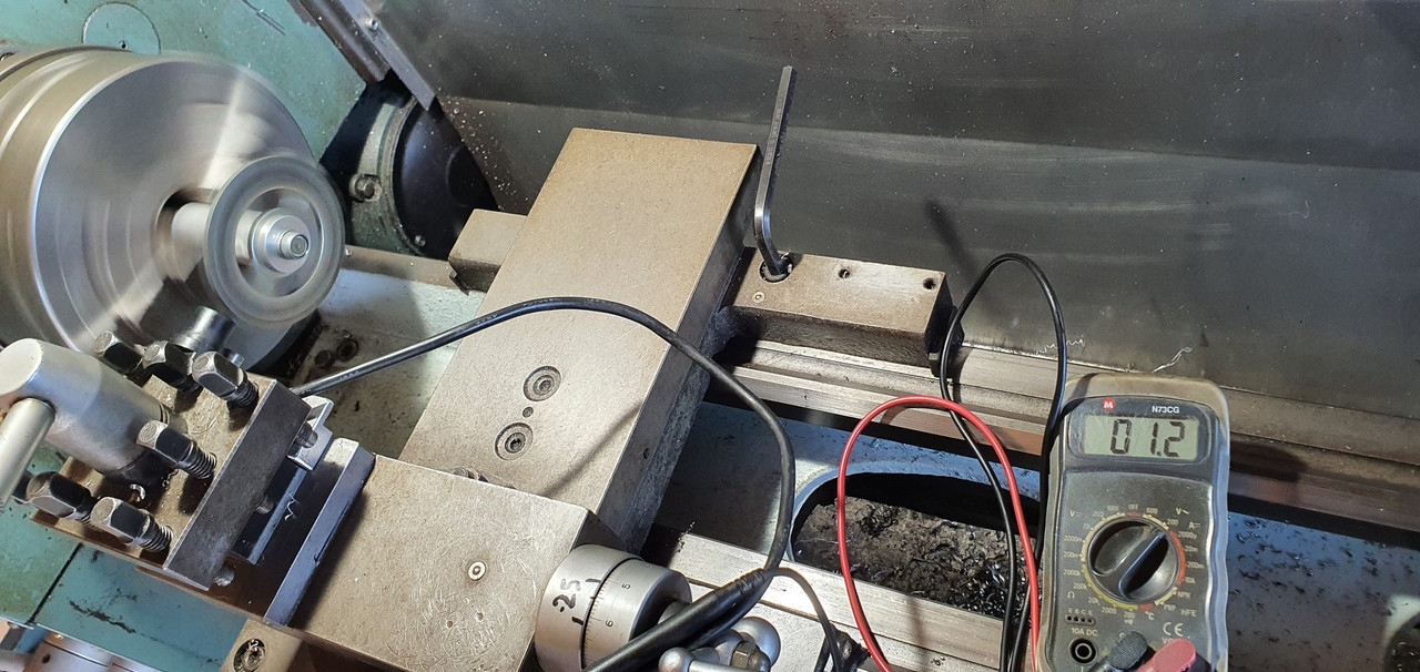
I spun the trigger wheel up in the lathe at various speeds and took voltage readings of both sensors.
The readings were very similar but I still couldn't tell what the actual signals are like.
The next morning I drove out to mates place and he set to work on my ECU. He compared the board to his spare Ms3x. looking for any differences. Remember I had bought this ECU secondhand from someone on trademe and was told it was working. I had swap some of the circuitry jumper wires to suit my application. Once he was happy there was nothing major missing on my board he got another spare ecu he had and ran up my sensors in his test bed to confirm they were putting out a good signal.
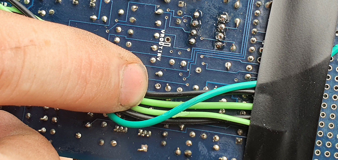
Then we (well - mainly him, I just stood about and learned) systematically went through the VR circuit looking at the signals on his osiloscope. Discovered that transistor U7 was faulty so he kindly swapped out the known good item from his MS1 which I'll find a replacement for him.
After that he found a loose, terribly soldered resistor in the circuit- when it was wiggled the signal would appear....
re-soldered that and hey presto - clean signal. Lots of other pins got re-soldered too.
The Goldwing pulse generator/VR sensor puts out a much weaker signal that the Mazda crank vr sensor. we double checked them against each other and the Goldwing item struggles at slow speeds (cranking type speeds) so I'll swap over to the Mazda item.
When I got home I quickly tried the repaired ecu out and now there's a good rpm signal but it drops out of sync but I took a log anyway. Then started making a new bracket to suit the Mazda sensor.
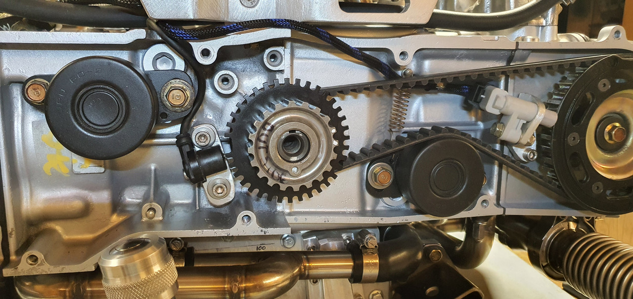
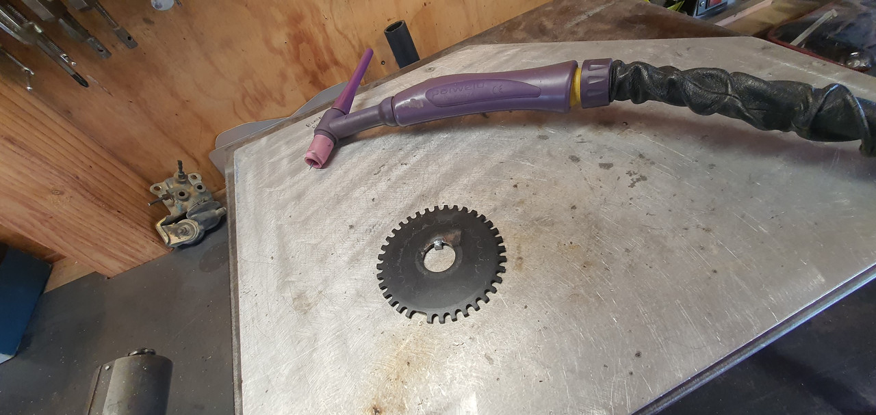
New vr sensor in place and wired up. I then had to remove one cambelt, which is so easy to do on these engines, remove the trigger wheel, file off the old key and weld a new one in place to suit the mazda vr sensor position which was now bolted in the other set of holes Honda used for the original 'pulse generators' as they call them.
New trigger wheel key peg..
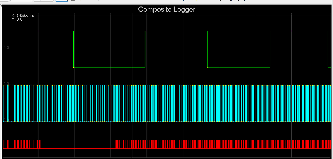
Finishing that lot got me to this point when trying it out that evening...
The red spikes indicate an out of sync situation and no rpm reading but at least the log was clean, consistant and rythmic. Something wrong in the settings, not interference. I tried changing various trigger settings but no luck
 I was tired so off to bed.
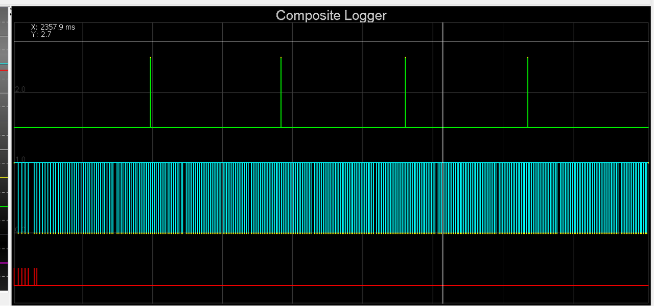
Following morning I discovered that when I was changing the trigger settings I didn't spot the prompts to power cycle the engine because I was still on the diagnostics page. So none of those changes took place until the very end when I had actually set it back to the typical default settings.
This time a power cycle after changing the capture to falling edge and I got this lovely log...
Yay!!!
Now I was ready to check the ignition coils and then the base timing. What else could possibly go wrong?
Coils all tested fine and the sparks were nice and clean looking. I then marked the timing mark on my custom crank pulley and tested the base timing. I was out by 4 degrees. Pretty happy that I had got my trigger wheel so close. Simply changing the trigger wheel offset value in the settings by 4 degrees had the timing marks line up bang on. Engine start up time was here! I went to bed happy, excited and somewhat nervous about what could happen, or not...
So this morning it was time to roll the engine out on the table to the front of the workshop, throw some fuel into the mix and see what happens. I set up the garden hose just in case, taped my phone to a light stand, started recording, tentatively went for a start and this is what happened...
Wow!!! Faaaaaaaaaaaarking awesome! What an occasion. What a milestone. Such relief and much giggling with joy. I couldn't believe it. First start on my own custom built engine and it sounds bloody amazing! That was starting on a basic universal base map loaded onto the ecu so I was really expecting a lot more mucking about with the starting settings to get a clean start. I was stoked!
I tweaked the cranking settings slightly and now it would start on the button after a few cycles...
I can only run it for a few seconds as there is not a drop of coolant in the engine. So my next job is to set up a makeshift coolant circuit using a spare Nissan micra radiator and setup the Davies Craig electric water pump. I can test for leaks and then I can really have a good crack at setting up a nice clean starting and idling tune.
I'm so happy!
Alex.
-
99
-
15
-
On 21/01/2024 at 21:22, Sc@ Chi said:
Ultimately, EVs won't stop climate change. But they help a bit and are inherently better - torque, pollution, simplicity, maintenance and so on. My take, anyway
Big thing is removing the pollution from the town/city centres - especially in winter when fumes seen to hang around longer.
I still feel NZ is missing the boat by not allowing the really small evs that have become very popular in europe to be legal on the roads here. Perfect little cars for folk who insist on driving to work and will never use public transport/bike/walk etc
Not only cleaner cities from the little cars but less car footprint jutting out into the road when parked up.
-
9
-
-
- Popular Post
- Popular Post
-
13
-
- Popular Post
Part 2... catching up now.
I finished what I needed to on the loom to enable testing of the injectors. I had made a simple little alloy jig that I could bolt the two rails onto and it sat high enough that 6 matching jam jars could sit below. We set this lot up on the big mobile steel bench and rolled it down to the front of the workshop near the entrance just in case it all goes a bit wrong. Set the ecu up along with a little 'ignition' switch and starter button for later testing of various engine sensors/ test running.
The tuning software that megasquirt uses, Tunerstudio, has a good set of testing programs built in including injector testing. Started using that and as soon as the injectors primed and started squirting we found a tiny leak.
Poos.
My home made rails were brazed together and there was one teeny bit the bronze hadn't flowed into leaving a tiny pin hole that let out a comical jet of fuel. Glad I tested them now.
Here under that lovely layer of carefully applied epoxy black...
was a tiny hole..
So out with the oxycet and I brazed it up.
Then re-tested the setup. No more leaks
We ran through a few tests and made notes on fill rates at different opening times/frequencies etc etc to work out the injector dead times. Not a crucial thing to do but since it was setup as such it seemed rude not to. The battery I had was a bit tired and my charger couldn't keep up so I installed a larger wheeled type of Nissan charger at the front of the workshop. This also meant the testing was being done at a realistic voltage you'd expect to see.
Happy the injectors were all matched and meeting the factory Nissan specs I packed all the stuff away.
Then I fitted the inlet manifold gaskets and bolted the inlet in place on the engine, followed by the rails, with the repaired bit hand painted with epoxy as best I could to match.
Next job to finish was the Bosch style idle air control valve. It had far too big in and out bosses so I machine up some stepdown parts to suit a more sensible sized tubing. I needed to mount it somewhere out of the way, safe and not on view because its not very pretty. I spotted a handy bracket on the bottom of the starter motor that has a threaded hole. Perfect! I made a little P clip to suit mounting the iacv.
which bolts here..
Like so...
I did some more plumbing to suit and after a few last little bits of wiring the engine was about complete. I fitted the pod filter I'd bought a while back directly onto the throttle body but it will actually end up remotely mounted in a cooler spot. I was just waiting on some posh ventilation hose to arrive.
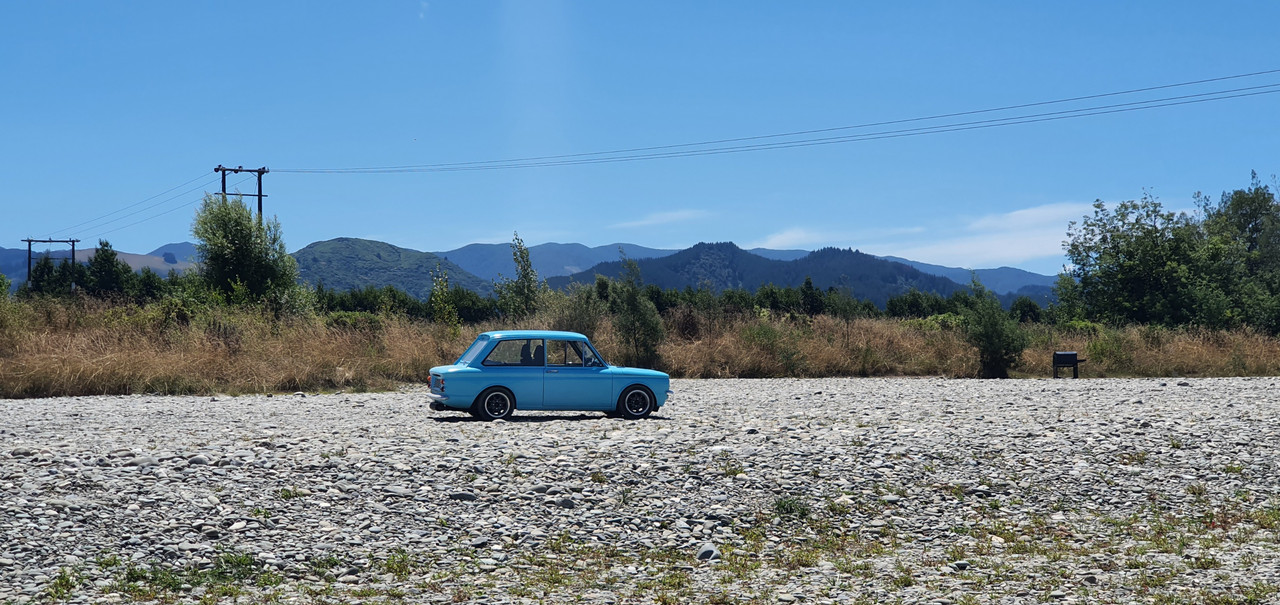
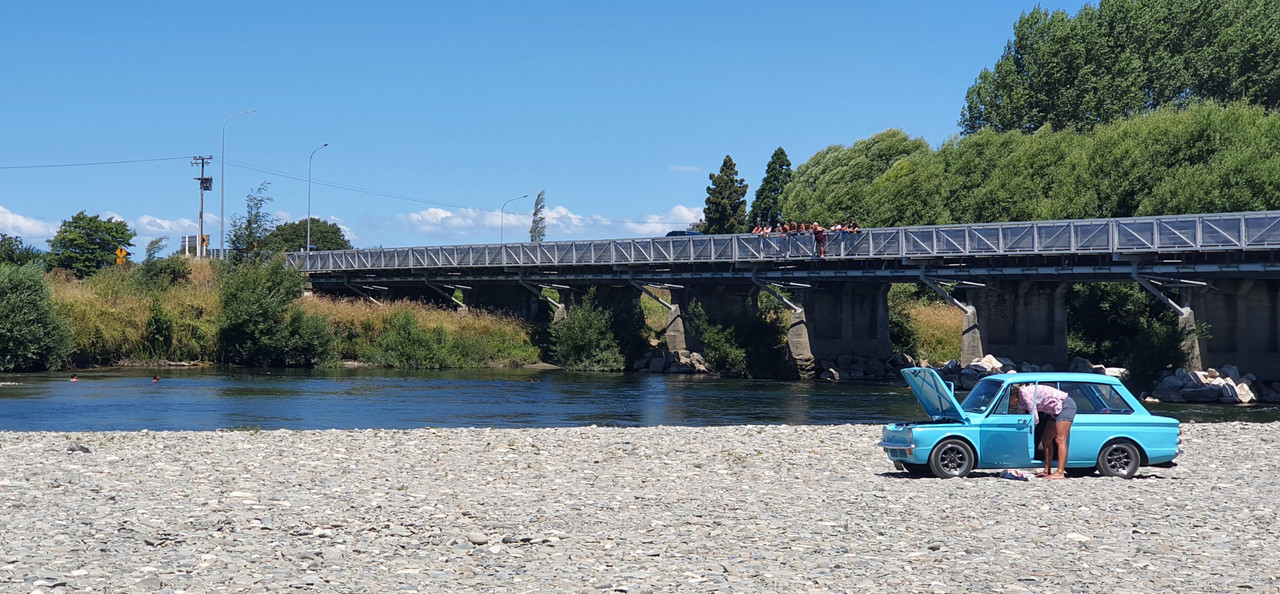
The Imp got a fresh wof and we took some pics of it when down at a local swimming spot near Motueka. It looked neat on the river stone so I took some pics..
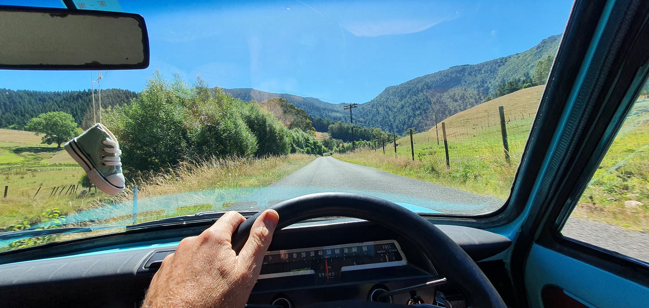
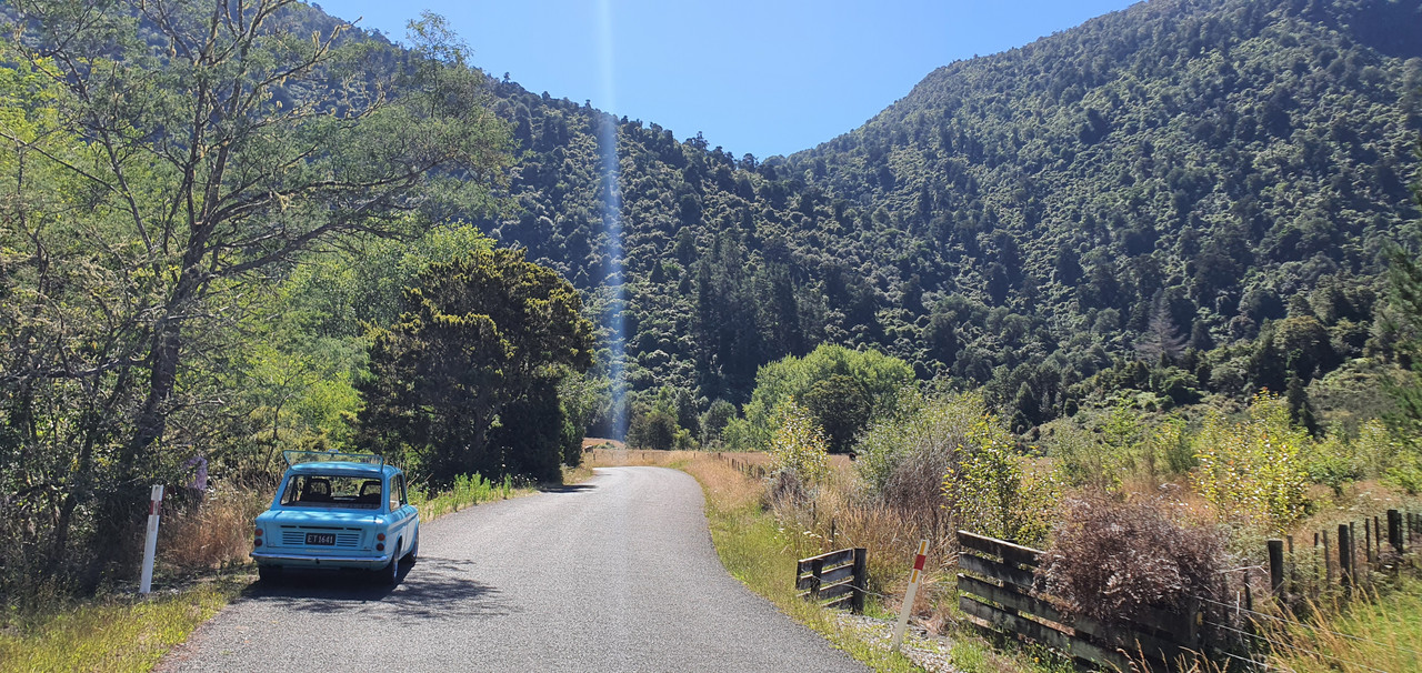
Went hooning up a local valley to get wild plums..
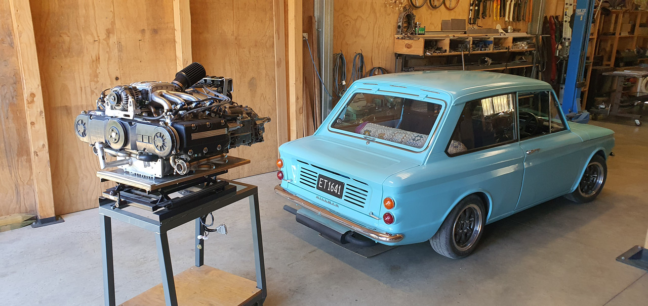
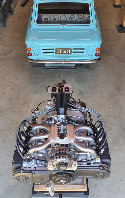
Got home and snapped some pics of the engine next to car. The perspective makes the engine look huge...
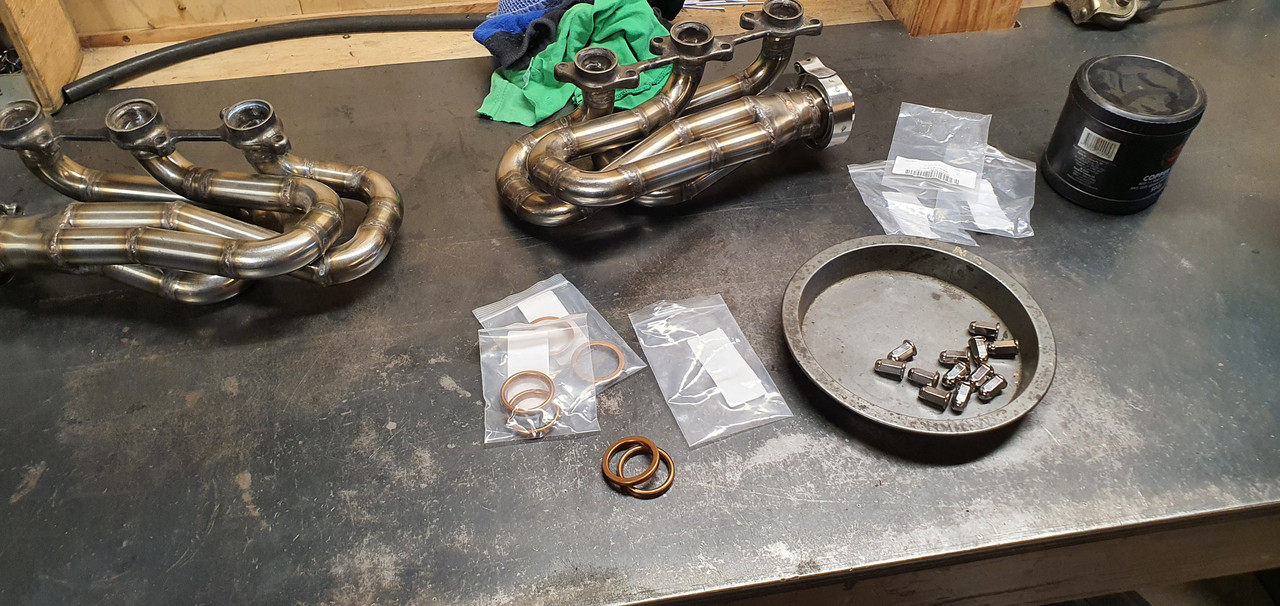
Next stage was to bolt the exhaust headers in place properly with the new gaskets and special nuts I'd bought.
But before playing with exhausts always be aware of the potential dangers, as so carefully pointed out in the workshop manual !...
Manifolds bolted up fine but a few of the nuts are awkward to get started as its tight on space around the header pipes. Next parts in the exhaust chain was the flexible joints.
My welding was improved a bit by wearing some reading glasses.
I guess I just have to accept that aging thing and embrace the power of +1.5 because now I could actually see what I was welding. Its still not instagram weld porn but it'll do for this project
Bolted the cross member in place and with a bit of alloy I was able to check the heights to weld the next sections at.
Unfortunately I must have fabricated the LH manifold out of line and I have ended up having to weld the secondary pipe at an angle to make sure the outlet heights match. It wont be easy to spot when its on the car, with a exhaust box hiding them. But I know its there...

Or maybe I don't bother with a single large tranversely mounted silencer and just run a couple of old dumpy mufflers...
I was now at the point I could fill the engine with oil and test the oil system. Quite a while back I bought some quality oil when on sale..
I filled the filter up first and then carefully filled the engine. Up until this point I had no real idea of exactly how much my resized sump would take before it got to height I wanted it at. I'd done some basic sketches and napkin formula and I knew it would be more than 3 litres. Hopefully more than 4. It almost took 5 litres to get to the halfway point on the sight glass and that will drop once the oil pump primed up and filled the oilways.
Cool. Great news then. I'm really happy it'll have a decent amount of oil in there.
Now remember back to around the end of December 2021 when I wrote this...
"Lastly I needed to bolt the sump cover in place. I had to think carefully about bolt placement for sealing purposes and get the bolts square. This sump plate is going to have to be sealed well because there is no usual high sided sump like most cars. Hence I built it rigid to help against flex. Good quality sealant will be the order of the day*
*It will leak. Its a British car. Its destined to leak."
Well then. Guess what. It leaked! Ha.
Just after patting myself on the back at having a great sump capacity the level started to drop and was leaving a good puddle on the engine stand top. So Hannah helped me move the engine so I could drain the sump and then I mounted the engine/box assembly into the spare imp. On a positive note I was chuffed with how quick and easy it was to bolt up in place by myself - all of about 5 or 10 minutes. Engine in place and with the car up in the air I took that above photo. I had a good idea where it was coming from and wasn't feeling to glum (not even a single toy was lifted from my cot)
I unbolted the sump plate and found the hole...
Back when I was machining the sump plate and milling the slots it wasn't initially clamped down tight enough and it shifted out of line without me spotting it. By the time I noticed it had moved it was too late. I had to weld up the resulting mess and re-machine that area. I thought it was all fine but I'd obviously missed a tiny pinhole, maybe exposed when I machined the inside of the plate out to take some weight off it.
The plate got a good clean (that threebond sealant is tenacious stuff! ) and I fixed the hole with a dollop of JB weld.
Took some pics of engine from below with its innards exposed..
Little pistons...
Bolted the sump plate back up, waited till the following day and refilled it. This time no puddles.
Yay.
While the engine was bolted into the spare imp I took the chance to double check measurements and clearances. It was all looking good and I was very happy that I had placed things ideally, especially as most measurements were taken in awkward areas by all sorts of various ruler/tape measure/level balancing acts. The ignition coils for example, just mounted on their makeshift bracket I'd made for bench testing, are actually almost bang on in the right place and only sitting a touch too high. The filter hose will just clear the underside of the parcel shelf and there's heaps of room for the remote filter..
Hose (turned up the day before) ..
Hannah's hand holding filter roughly where it will be mounted to the bulkhead...
Lots of room out back between engine and where the removable rear valance bolts in place..
and lastly, the 'Mandalorian spaceship' will not at all be hidden by the rear parcel shelf ..
Engine is now out and back on the bench for more 'bench testing'...
-
69
-
10
-
Yeah that looks correct.
-
1
-
-
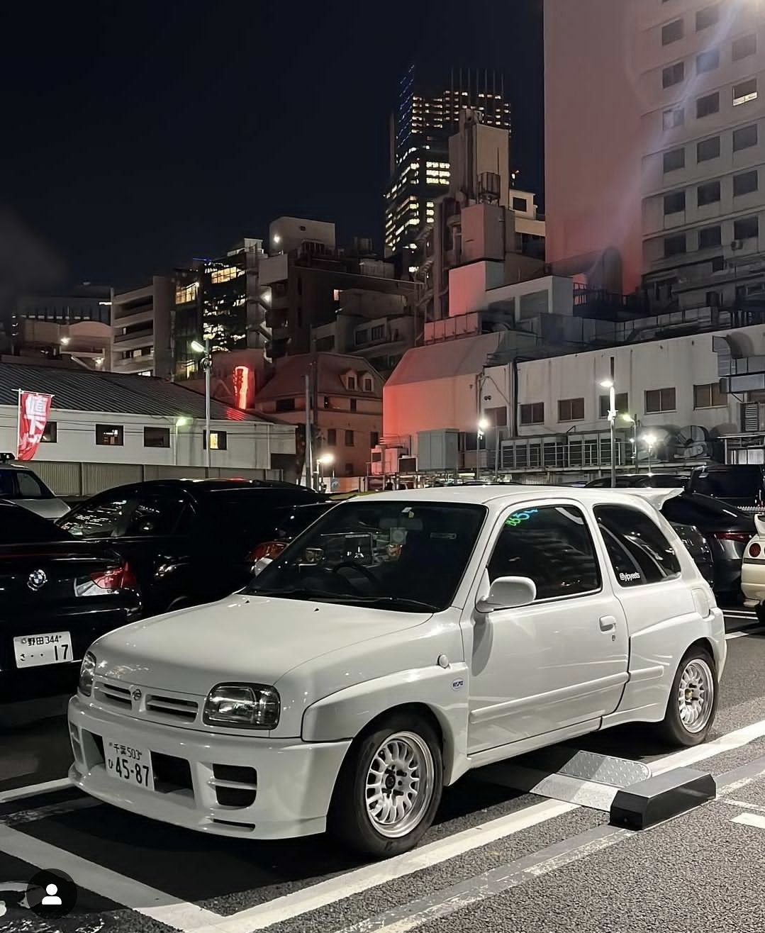
Never seen a march with that colour but they sold lots of micras like that in Europe. Way ey I've seen some Bobby dazzlers on t' internets
-
Or is that just faded eh
-
2
-


.JPG.aad410b8d0fc164f9dafbf23574d0bcb.JPG)
.jpg)
.jpg)
.jpg)
.jpg)
.jpg)
.jpg)
.jpg)
.jpg)
.jpg)
.jpg)
.jpg)
.jpg)
.jpg)
.jpg)
.jpg)
.jpg)
.jpg)
.jpg)
.jpg)
.jpg)
.jpg)
.jpg)
.jpg)
.jpg)
.jpg)
.jpg)
.jpg)
.jpg)
Yoeddynzs 1965 Hillman imp 911 build. Flat six in....
in Projects and Build Ups
Posted
Now I had an engine that starts and runs for half a minute I wanted more. I needed a makeshift cooling setup.
I had a spare Nissan March radiator and fan kicking about so that was called into action. I whipped up this beautiful bit of carpentry artwork..
Using a collection of spare hoses I connected the dots between the engine, the electric water pump and the radiator...
I started filling the system with coolant mixed at 35%. Remember this bit. It comes back to haunt me later.
The whole system wouldn't fill up due an airlock in the coolant pipe from the opposite head. There was no way this was going to shift. The standard goldwing cooling system has both top pipes meeting in the middle at a thermostat block so they just bleed the air straight out naturally.
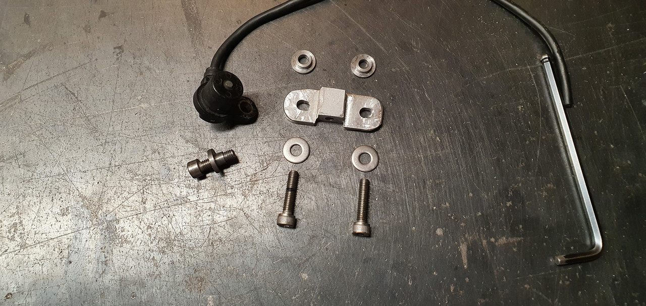
I needed a nipple.
I looked in my collection of various sized nipples and other brake fittings...
Found this small nipple which was perfectly formed and a lovely size...
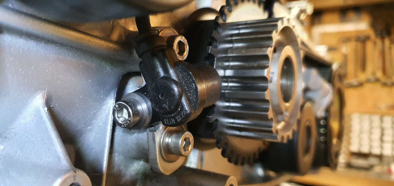
I needed a boss to inset the nipple into. I machined one up and tig welded it carefully onto the top of the coolant pipe, in a discreet place tucked away behind the alternator so the nipple isn't immediately on display unless you look for it.
Now with the nipple cracked open the large airlock was able leave via some clear vinyl tube. This allowed almost 1.5 litres more coolant in. With the water pump in override mode and twisted sideways I was able to bleed the pump out and the coolant was circulating fine.
Next step before running the engine for an extended period was to sort out the O2 sensor positioning. Luckily a nice stainless boss from ali land had turned up so that was welded in place ...
I was very happy that I could run the sensor cable around behind the oil filter, completely out of harms way and about as out of view as I could hope for. There's no hiding the ugly sensor sticking out of the exhaust but that's just life.
The exhaust also required a token amount of silencing so I popped the old motorbike silencers outside on the truck deck and painted them with black high temp paint, mainly so I wasn't looking at ugly rusty things..
I also had to do a little bit of extra wiring. The water pump and its controller, the O2 gauge and not to forget the remote unit for the mandalorian spaceship interior lights..
I also wanted to slot my throttle cable adjuster base so I could easily remove the whole cable outer and inner without fuss...
In the mill with a tiny slot drill...
I made a hand throttle using a spare mountain bike brake lever and a bit of suitable alloy tube. But I needed a tiny solderless nipple for the cable end. My tray of bike cable adjusters and such what had nothing small enough so I machined one out of brass and used a 3mm grub screw...
Now I had some basic throttle control without reaching over the engine.
Time to start it up which happened without any fuss. The coolant system worked fine and the engine rose to temp quickly and smoothly. The fan kicks in above my for now setting of 98 degrees. I intended to tune the idle first, once the engine was hot and not using any of the warm up tables etc. But the idle control valve was still passing a touch too much air even when 'closed'. I wound the idle bleed screw in to its stop on the throttle body but still it was idling at 1200 thereabouts. If I blocked the iacv inlet with my finger the revs would drop to circa 700-800. I could also hear a very tiny vac leak from the spaceship window (plenum lid)
Bloody mandalorians with their terrible glazing skills.
Tightened the lid bolts down and its not bad. Main issue really is the idle valve. I might just make my own like I did with the Mazda V6. Rip the guts out from a stock Mazda item and machine a suitable body to take the solenoid and valve head.
Another issue far more critical that really had me feeling quite low was this...
Coming from here...
Coolant gallery at base of the head gaskets on each side. It's not dripping but weeping and only once up to temp. I was gutted. I had to travel over to Nelson city that afternoon in my Imp so while there I popped into the engine reconditioners I know there and explained the problem and showed them the photos. Instantly they said I shouldn't have done my first fill with coolant. Apparently it creeps very effectively through any tiny gap before the head gasket has sealed and its slippery/slightly slimy consistency stops the paint on the gasket sticking to the surfaces. All is not lost though. I was instructed to drain the system of coolant, flush everything through thoroughly with clean water and let it dry. I did that last night. I then ran it a couple of times this morning with nothing in it for no more than 30 seconds, allowing it to cool between. Hopefully this will have dried it out and help it seal. Then I was told to just run it with water for a while and see how it goes. It might be ok. If not then they have a kiwi made product called sealwel that many kiwi/aussie reconditioners use with troublesome gaskets. He reckoned its not failed them.
Worst case scenario is a pair of new head gaskets.
and no coolant when setting them !
I might just order the gaskets just in case so I'm not ever in a position where I have to wait later on down the road if the above doesn't work.
So yeah. I hope its ok and I've plenty of other things to do anyway. Like sort out the alternator that seems to be defective. This one. I need to either fix it or find an exact replacement because the spaceship has been built up to it and there's no room for anything bigger/longer..
I have also chopped the throttle body spring back a half coil for more tension on the throttle shut. It wasn't closing completely by itself against the strength of the engine want of air.
Oh yeah I took a vid") ...
...