zep
-
Posts
4,743 -
Joined
-
Last visited
Everything posted by zep
-
Thanks man.
-
@cletus I saw in another thread you mentioned that Wilwoods with integrated handbrakes have failed the cert test. I wonder if you had heard or seen anything about these: https://fastlanespares.co.nz/products/wilwood-powerlite-caliper-with-handbrake
-
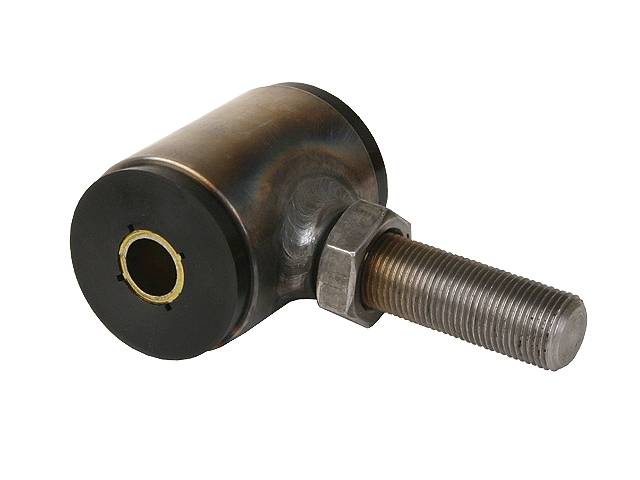
Thanks. I've checked the manual and it seems easy enough. I wanted to use regular bushed joints at each end to fully reduce the harshness. I guess that I could always swap them out for heims if the thread is the same.
-
When building 4-link bars, how do I determine what bush ends are legit and what are not? Also, are there per-determined widths that they should be? Most seem to come in 2.5" and 3". What about the centre bore/bolt size? Some are forged and some are welded: vs

-
Apart from the wheels, what other items do the new certs have photos of?
-
Yeah, I read the Accord Euro R ones are pretty decent.
-
Does this help at all? https://rsmotorsport.com.au/files/Identifying_Toyota_Hilux.pdf
-
Now that the canal has been cleared, my overnight parts from Greece can finally get back on track.
-
Thanks man. He's out west so this should be good.
-
I think I like the idea of the 4 bolt back mount ones, rather than 3 side bolts. For mashing, etc
-
A colleague has a 205 gti with a busted starter. Can anyone recommend a new unit? Rock auto has them for about $120nzd, elsewhere they can go up to $500! Any suggestions? Cheers.
-
What year you thinking?
-
Cheers all. Might hit up Pick a Part on the weekend and see if there's anything I like the look of.
-
Are all pedals essentially the same? They are mostly 6 wire, right? If so, essentially I could just go to pick a part and grab any one that I liked the look of.
-
The VE pedal looks way easier to mount than the nissan one.
-
Thanks. I'll see what I can do.
-
Yeah, I'd be happy to buy the bosch stuff, just seeing if it's possible to keep the costs down. What are the ve commodore pedals like? As for the 350z stuff, it seems like it's only a hundred more to get new bosch stuff, warranty and all.
-
I'm looking at 65-70mm, or b there abouts. I do have to say that the bosch and 350z tbs look quite nice compared to some others :/
-
Hey all, I'm looking to purchase a drive by wire pedal assembly and throttle body. Just wondering about opinions on these options. Will be most probably using a link g4x fury. 350z pedal and tb, used at $350+gst - link lists this tb as one they "support" Bosch Motorsport pedal and tb, about $500+gst A mixture of the above? Or I can probably get a cheap pedal from something at pick a part. I've heard subarus are good, any other options? Cheers
-
Do you have any examples of this? Could that just be roll Cage foam?
-
Ah yep. I imagine even the b pillar would be within 300mm. There are a severe lack of new retro inspired buckets that look good.
-
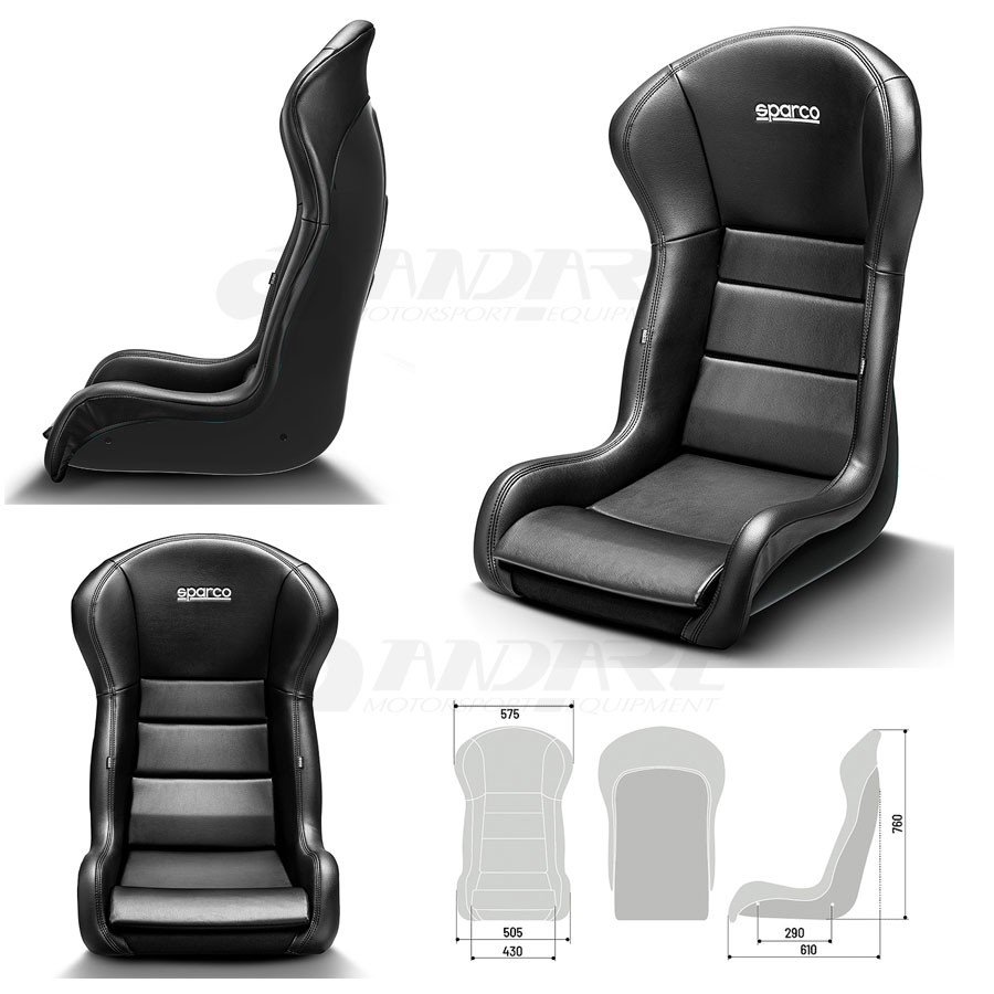
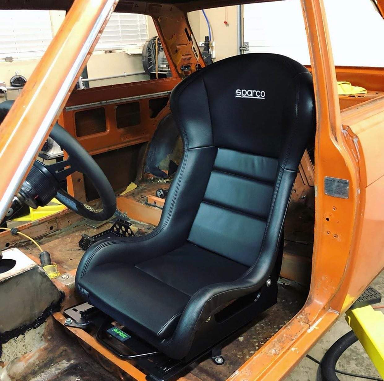
I'm quite keen on these new Sparco Stradale seats for "oldschool aplications". Issue is that they have no head rest. Is this going to cause an issue? For reference, my current Racepro seats are 810mm on the F dimensions. Here's the only pic of them in a car (Datsun 510) that I can find:
-
Way off topic bro, this is not a v8, or a drag car, and it's GM man. Shieeet! I reckon I'm just going to go directly above and below the axle centre. The largest spread I can do at the diff without fouling on things. Then try get the IC around the flywheel on the anti-squat line with the arms as parallel as possible, potentially moving the upper chassis side down 2mm for every 1mm the lower arm goes up. If I keep enough holes either side, I should have enough room to tune it.
-
Yeah, I thought about it. Will look into that a bit more. Otherwise thanks everyone, I'm more confused about what to do now
-
Does the distance between the upper and lower arm make a difference? Or where they are in relation to the axle centre?