Themi
-
Posts
73 -
Joined
-
Last visited
Everything posted by Themi
-
Yes, I hear this haha. Cool as, I might keep hunting through forums and see what people have successfully run on a ZC. Lots running different td04 and td05 combinations, generally with quite large turbine housings yes. I think the D-series enthusiasts Facebook page had quite a lot of love for td05. I think popping a block would be upsetting but yeah my rods aren't going anywhere. They'll take whatever I throw at them.
-
That just seems huge - I don't know if the s40-b000 will take much more than 250whp, 300 was a stretch but I figured a light car would reduce the amount of stress in the gearbox. The other issue is the sleeves - I'm running stock sleeves and not sure they'll hold much more than a 2860 can give. Do you have a dyno sheet from the b16 by chance - so I can see the response? I'd imagine if a 3071 size can get in boost by 3k, the 2860 will be spooling by 2! This seems a bit more practical for the build, to me. Regardless I do appreciate the input, I haven't completely dismissed the g25-550 I will just need to do some more research.
-
Really? This is interesting thank you. I have done some limited research and I'm wanting to get into the high 250whp on full boost. I did some googling which suggested a gt2560 won't get me there hence the gtx2860 which is expected to get about 300whp with a better spool (gtx vs gt). My "knowledge" comes from mazdas which flow like shit. The pulsar GTX2860 Gen2 comes in a .64 or .86 5bolt rear or I can get the .82 3" vband rear housing. I don't have a big enough wallet for the real deal Garrett haha. I was thinking of the VBand .82 outlet because I dislike bolted flanges. What turbo would you be suggesting if you had the choice?
-
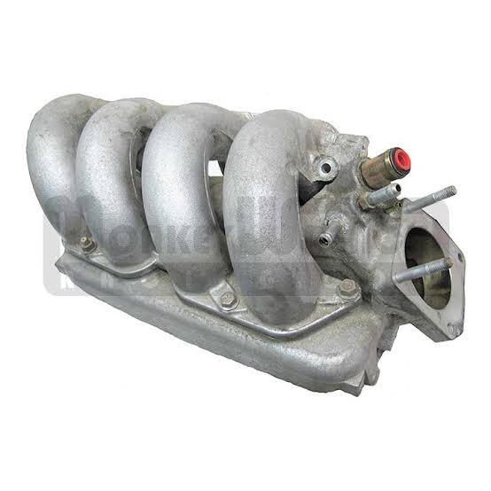
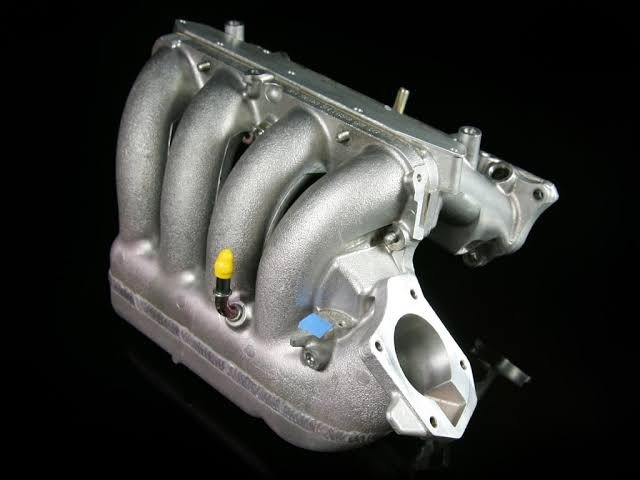
I guess it isn't exactly "build" related but more theory-crafting. This person has done an extremely tidy job of putting a DOHC ZC into a 1st gen civic. The big concern is that half of the engine bay is taken up by intake manifold, hence the comments on the main thread regarding RBB or 2zz intake manifold. Both of these have low-mount intake manifolds, with the runners curling over the top. It is worth noting that my ITB manifold on the Mazda was made by welding a ZL-VE intake manifold to a 4age intake manifold, both chopped off by hand with a hacksaw. Here is one variant of the 2zz intake manifold. The 2zz has similar port spacing to the ZC, so it won't be too difficult to cut and shut the stock ZC manifold on at the start of the runners. The removable plenum that came on the corolla 2zz (but not the celica) will help with welding the lower section of runner. Here is the K24 RBB intake manifold: The key benefit is that it unbolts half way through the runner. This means if I modify a stock ZC intake manifold to match that first section of runner, I get easier access with a die grinder to port it out. The drawback is that these are often more expensive, and are larger than the 2zz manifolds. Additionally the K24 has much wider port spacing, so mating the two manifolds might be a non-starter. Regardless, it will be a bit of a journey to make an intake manifold fit for the engine placement I am after. This is not something I specialize in and it is hard to find exact make/models of car for specific intake manifolds at wreckers. It might just require a good half-day of walking through pickapart to find the perfect manifold. I'd love to hear anyone's ideas on this, tell me how bad of an idea it is or suggest a better intake manifold, I'm all ears!

-
Placeholder first post for my 1979 civic build. Link to build is here:
-
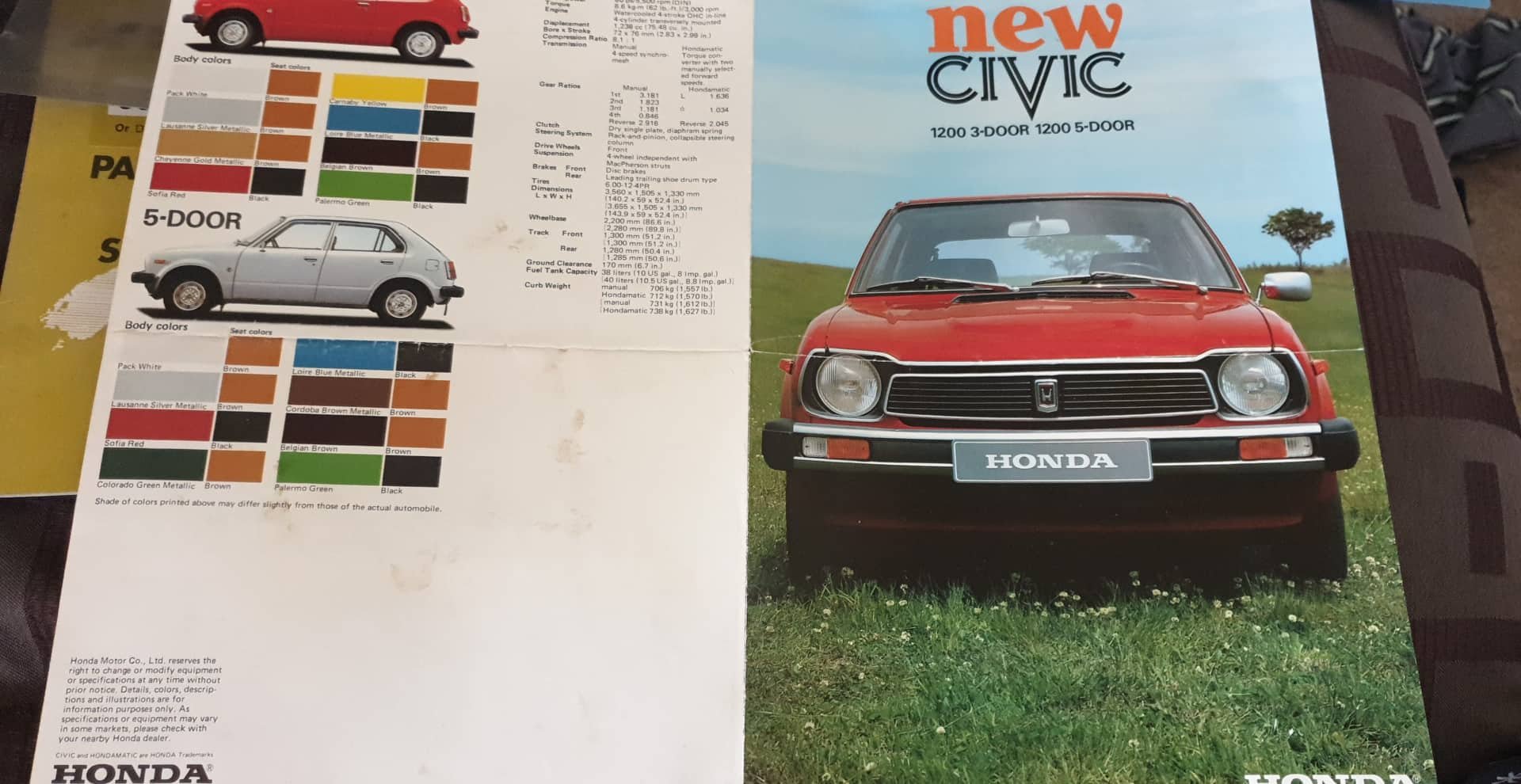
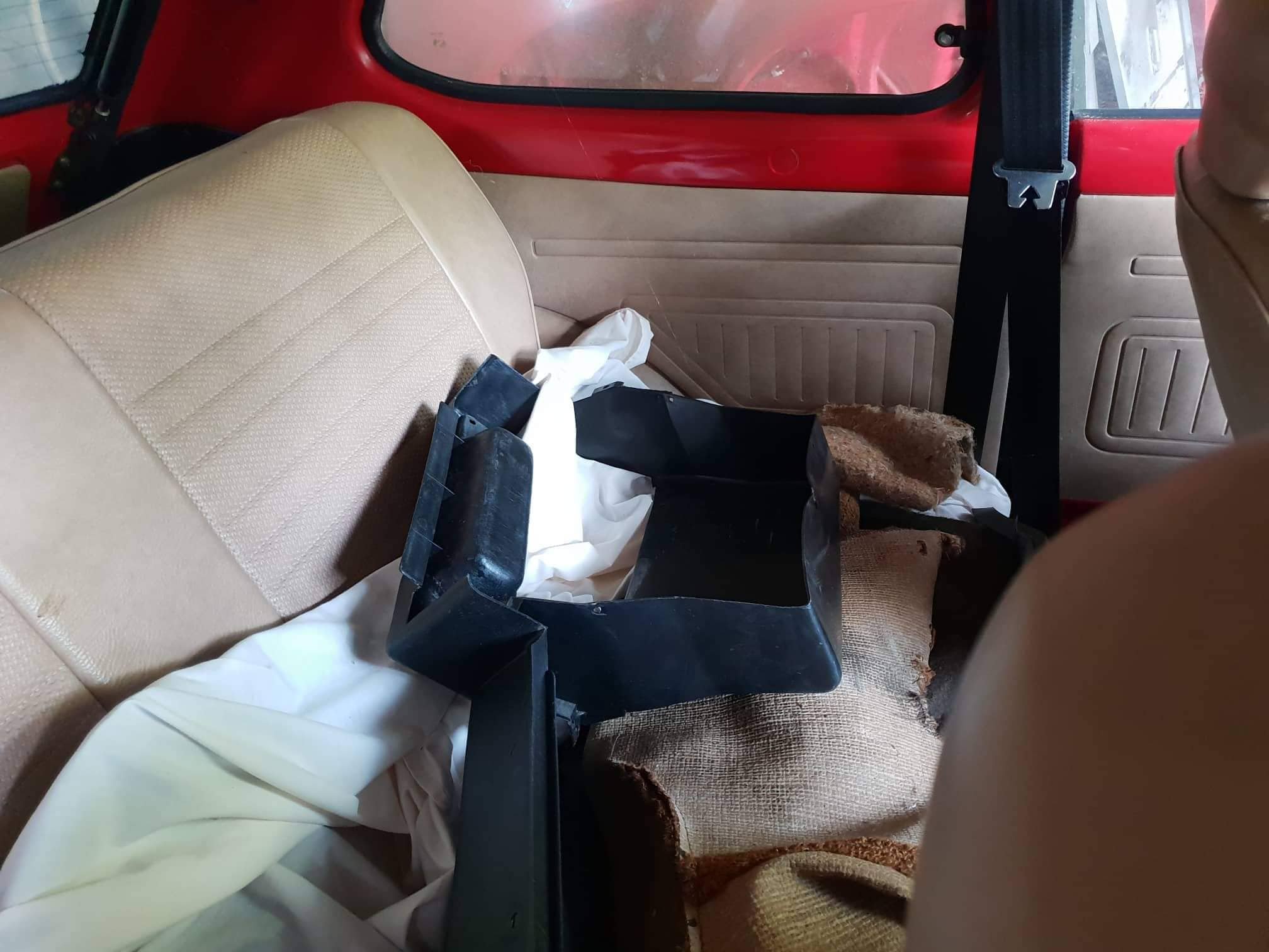
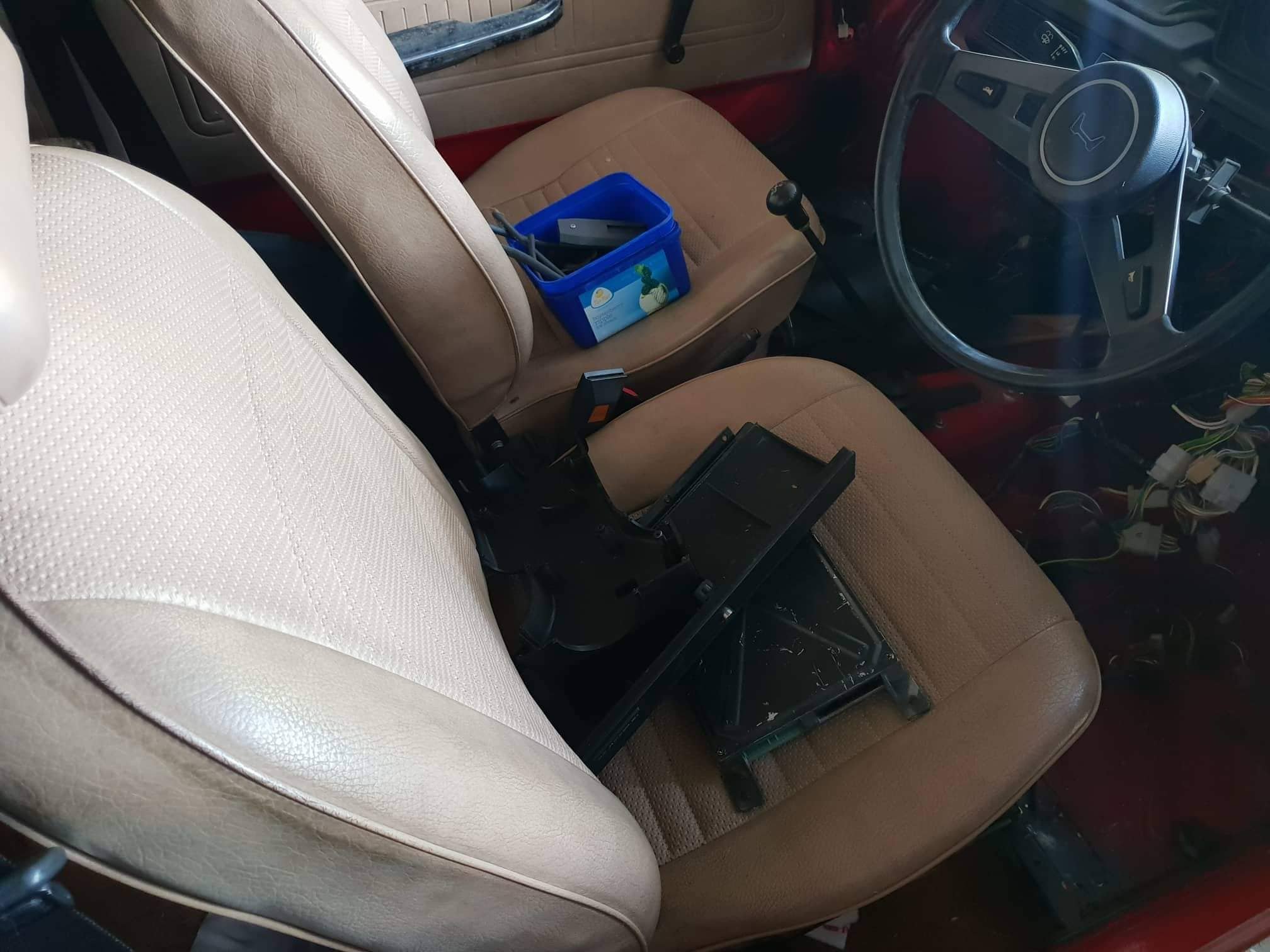
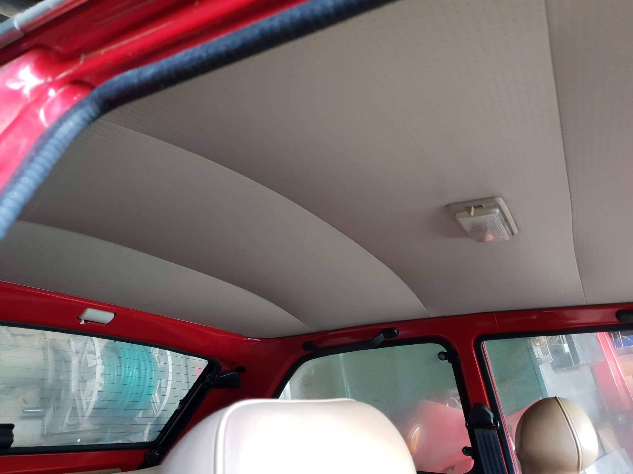
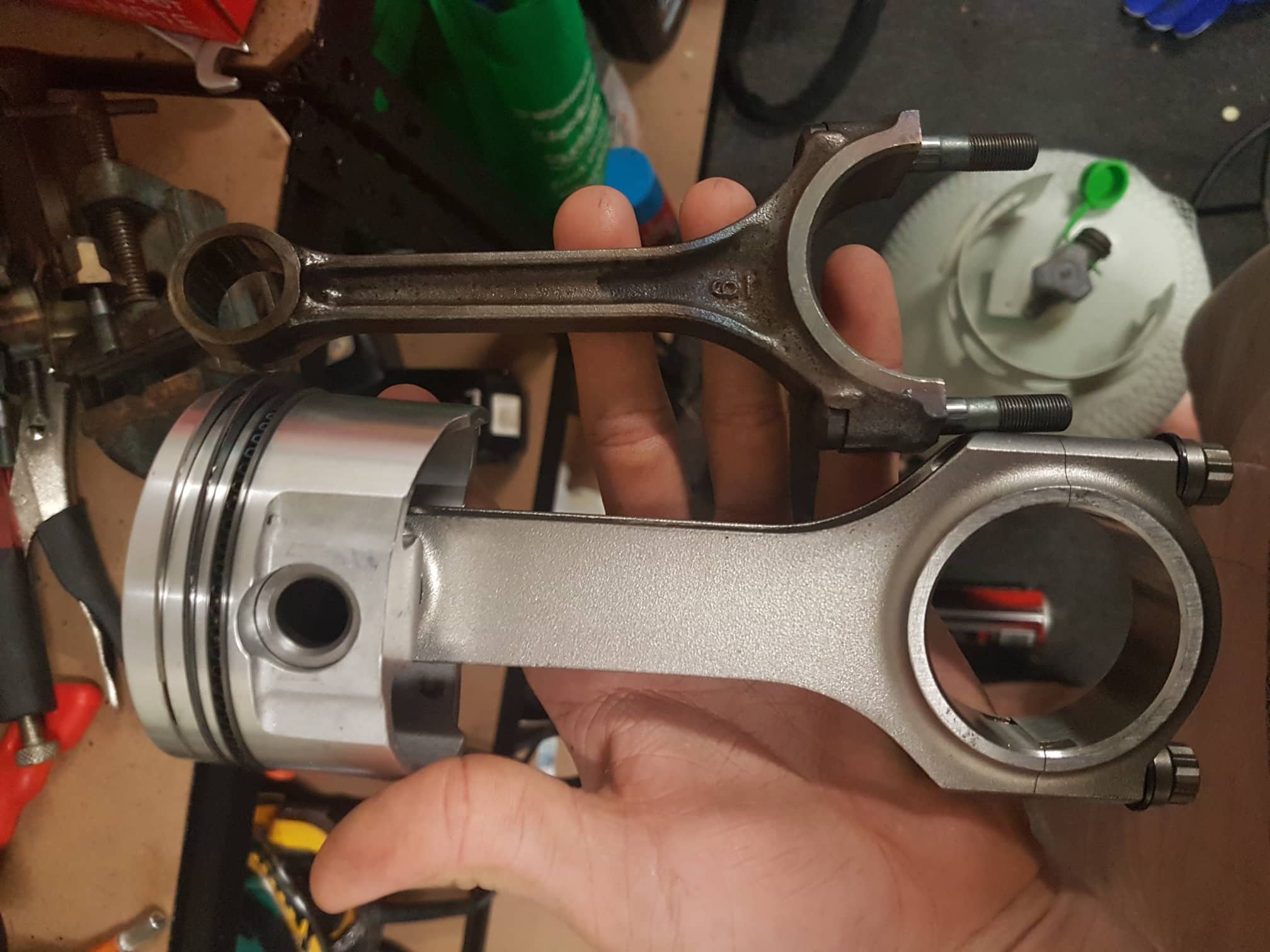
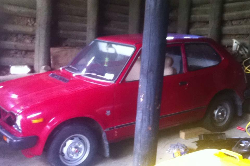
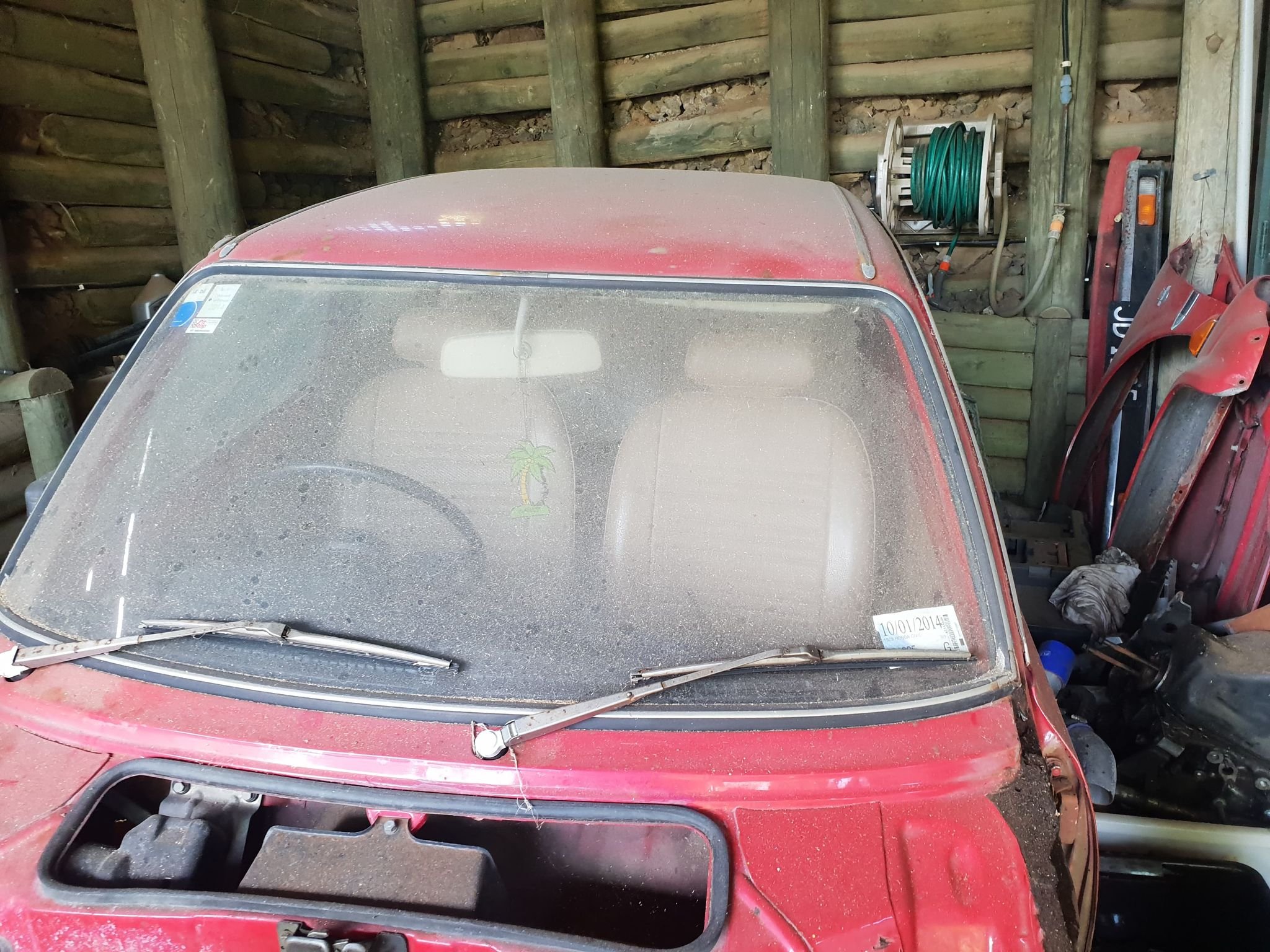
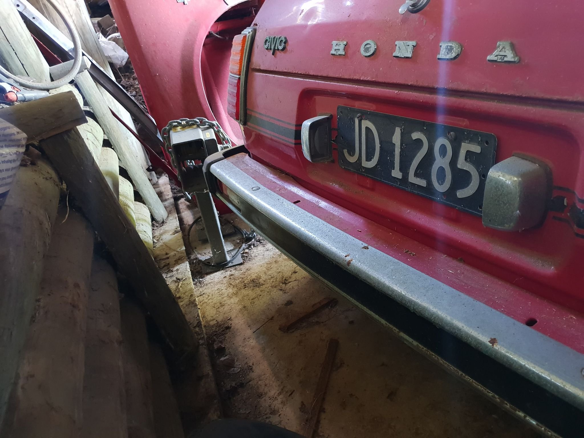
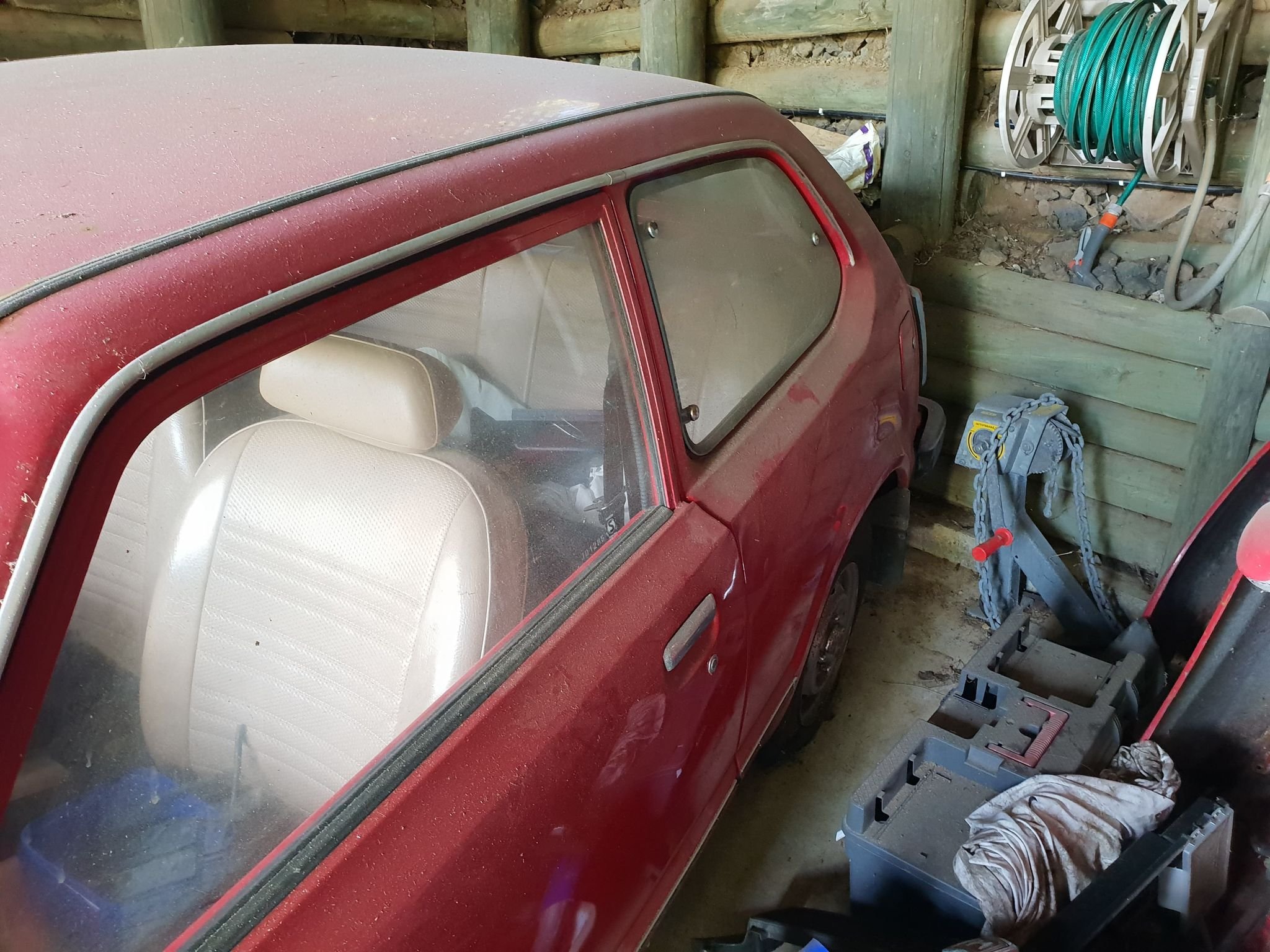
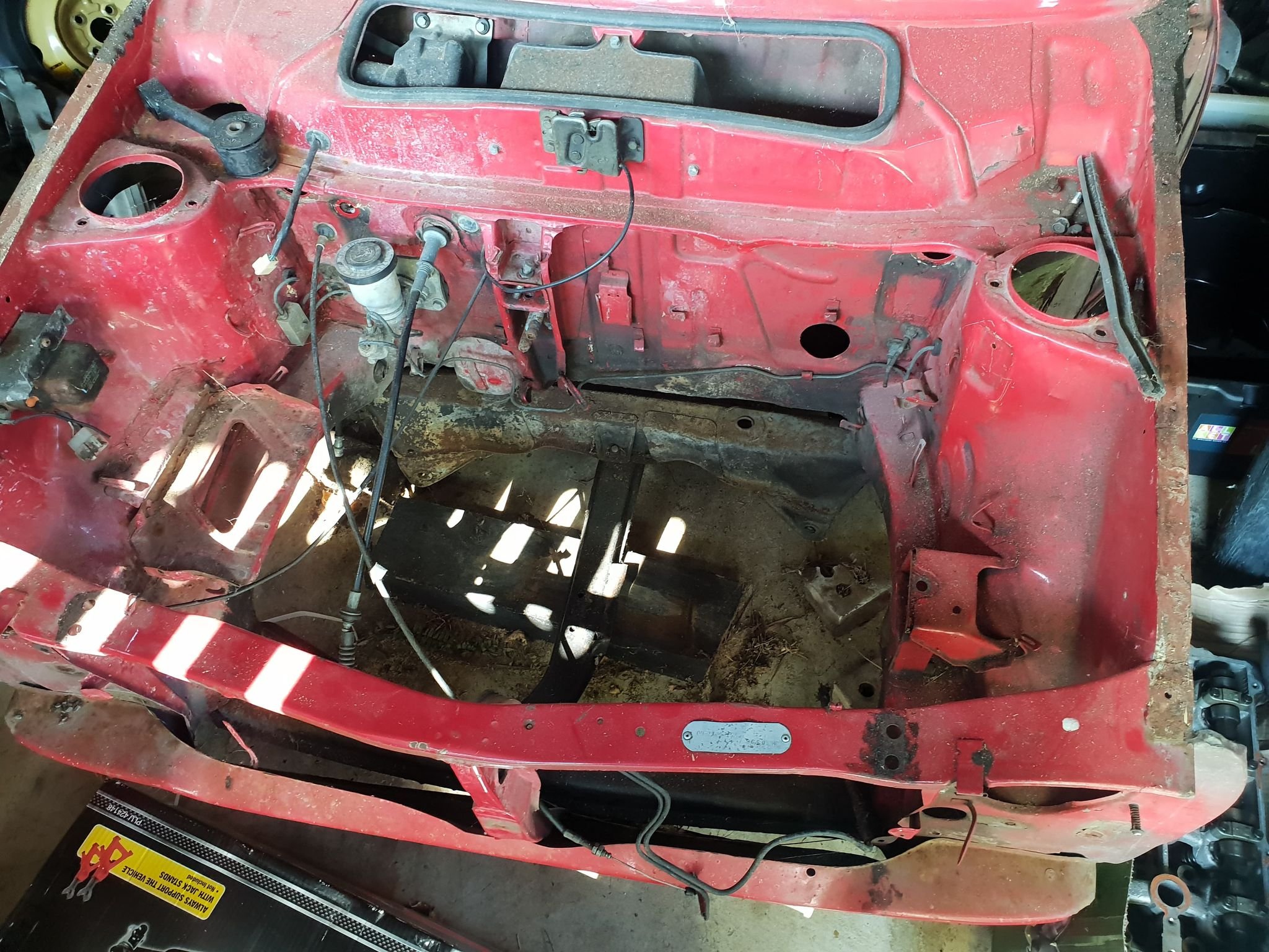
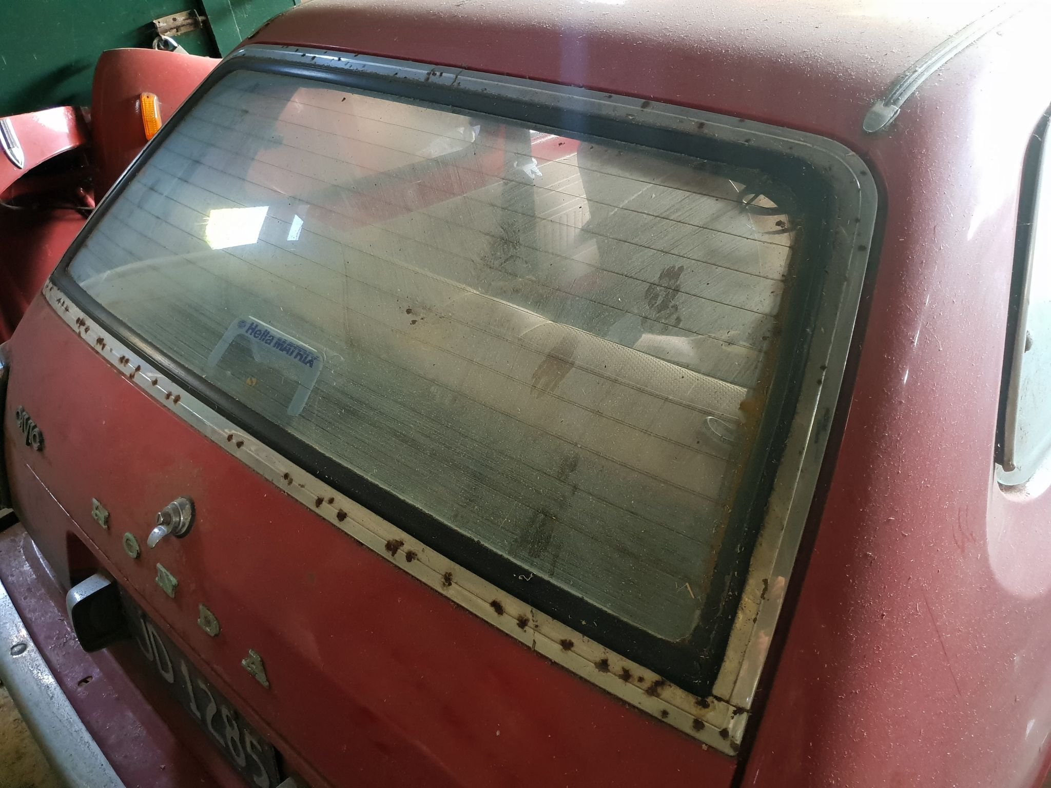
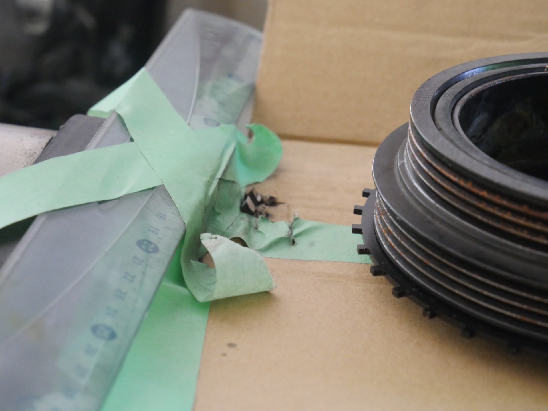
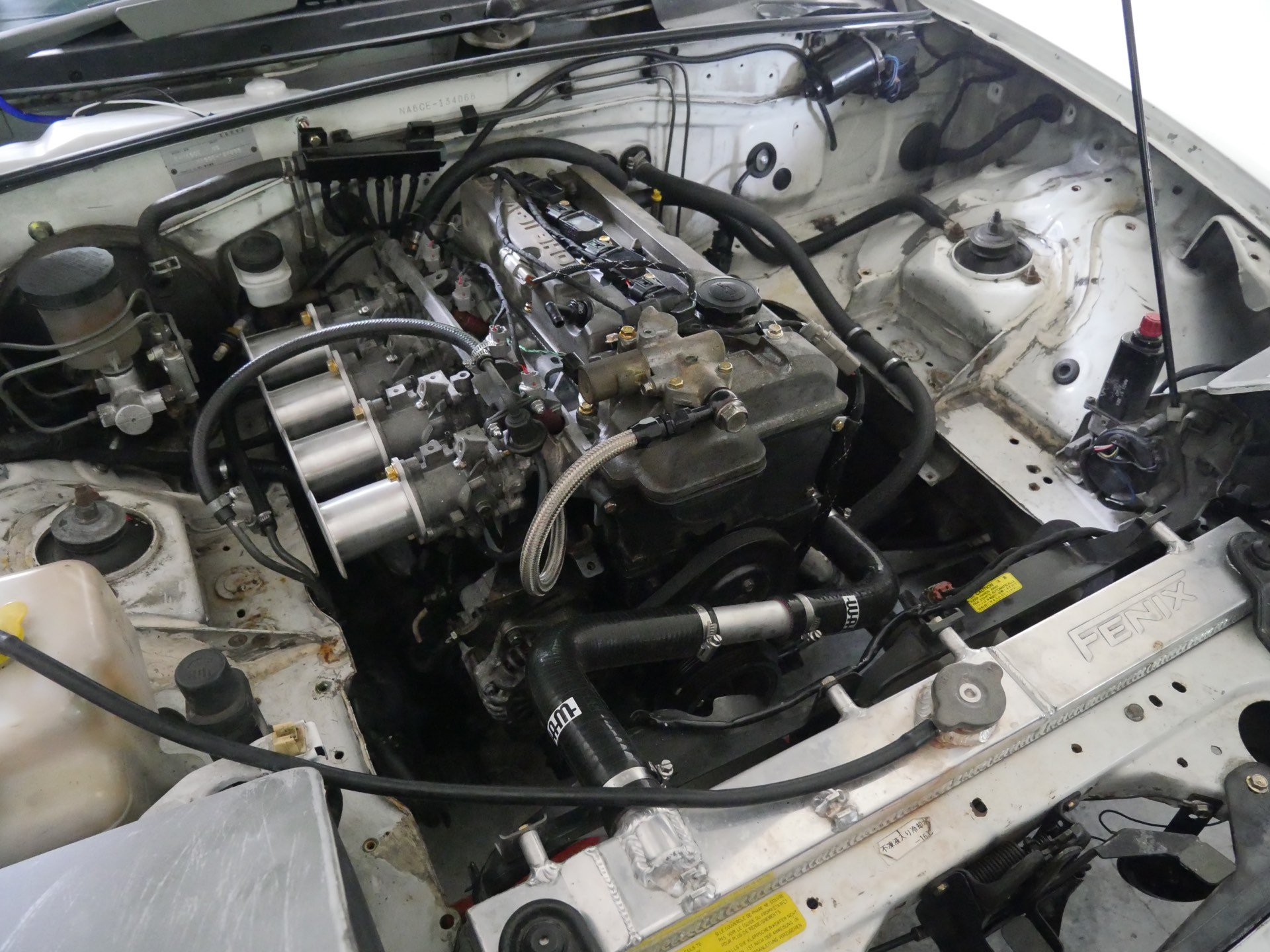
I guess this is just a placeholder first post for this car. It has been sitting under my dads house since maybe 2015, and last had a WOF in 2014. First pic is when it was first "parked". This is the only picture I can find from back then, when it actually looked like a car. It is a 1979 Honda Civic 1200, made in Nelson and originally purchased from Percy Motors Auckland on the 28th of March 1979, approximately 18 years before I was born. It has 8X,000km's on the clock, and service history for the majority of its life indicating it did not roll over. The original documentation said it was in "Signal Red" but I believe the actual colour (from the sales brochure) was Sofia Red, with the brown interior not black. This could have been swapped in, but the head lining matches brown so I'm not so sure. I purchased it with a half-complete City Turbo 2 engine swapped in, which was seized from sitting for too long so I gave up on it and pulled it out. I sold that with all of the (many!) city turbo bits that came with the car. The exterior of the car is now in pretty poor shape, with quite a bit of surface rust coming through under the paint, and some areas (like below the A-pillars) with really quite bad rust holes. I'm not sure what it is like under the car, but it was fine when I got it! The interior was pretty much immaculate, except for some minor damage to the wood veneer on the dashboard and the carpet had been stripped. I managed to acquire a DOHC ZC engine (d16a8/9) from a CRX, with forged pistons and H-beam rods. The details of the me purchasing this engine in ~2018/2019 are fuzzy, but I believe it was built for a turbo in a track car. Here you can see the new rods compared to the stock ones. The plan is to have the engine swapped in as soon as I get the car moved, with basically a hack-job of motor mounts just to get it in roughly the right place. Then I will worry about axles, suspension and chassis. I intend on using a GTX2860r Gen2 on a log-style manifold to suit the space restrictions, and modify either a 2zz-ge intake manifold or K24 RBB intake manifold to mate up to the ZC head. The intake manifold is about 1/2 the length of the engine bay in its stock form. While people have made this engine fit with a small-ish turbo, I don't want to modify the firewall at all just for an intake manifold. This will not be a fast project, I don't even have the car yet! But hopefully the end result will be a fast project. Link to discussion here:
- 3 replies
-
- 28
-

-
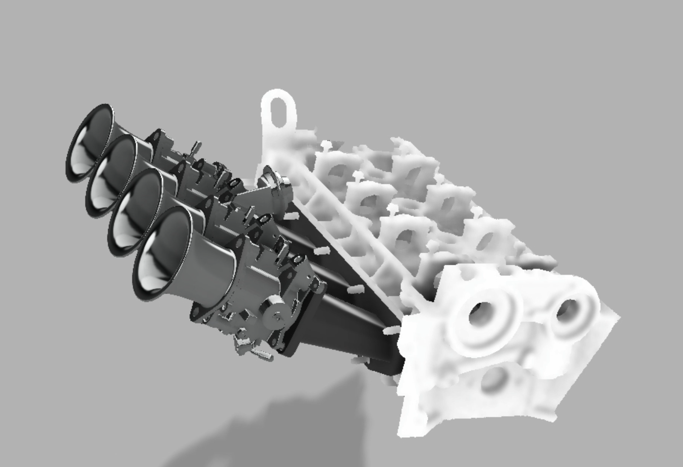
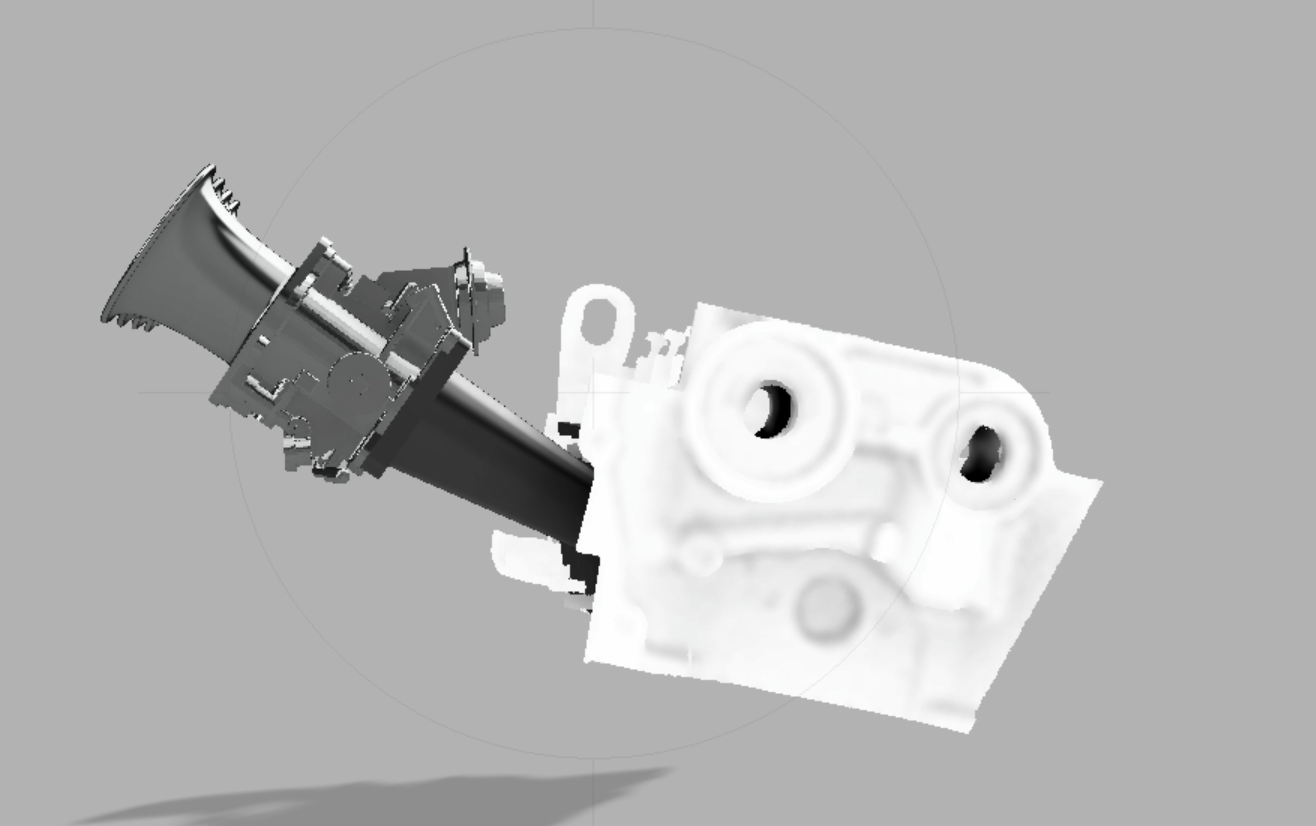
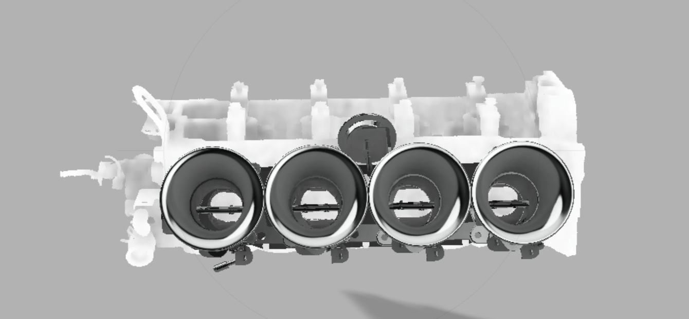
Is the entire assembly on the piss? Why yes, yes it is. My rx580 reeeally has a hard time with this many faces. For fun I loaded a low poly version of the cylinder head into fusion, just to see how it would look. Also there is a mesh of some 4age silvertop ITB's in there, and some short trumpets I modeled a few years ago. Attempting to rotate the entire assembly just causes crashes, so I left it as is. Currently the flange on the car turns sharply downwards right after the port, and the throttles are actually below parallel with the deck of the engine. I have more work to do, but it is cool to see the thing come together in fusion! It is really interesting reading up more on runner length, shape, cross sectional area etc. It looks like many of the things I wanted to model have already been done on test benches, so perhaps it is just the case of trying a few things out?
-
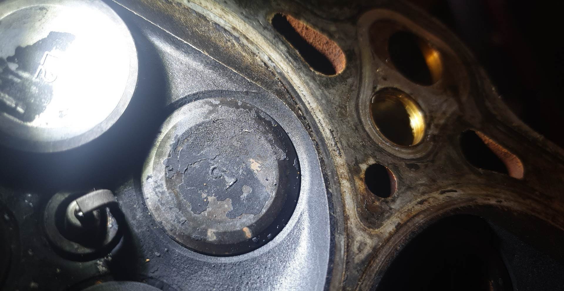
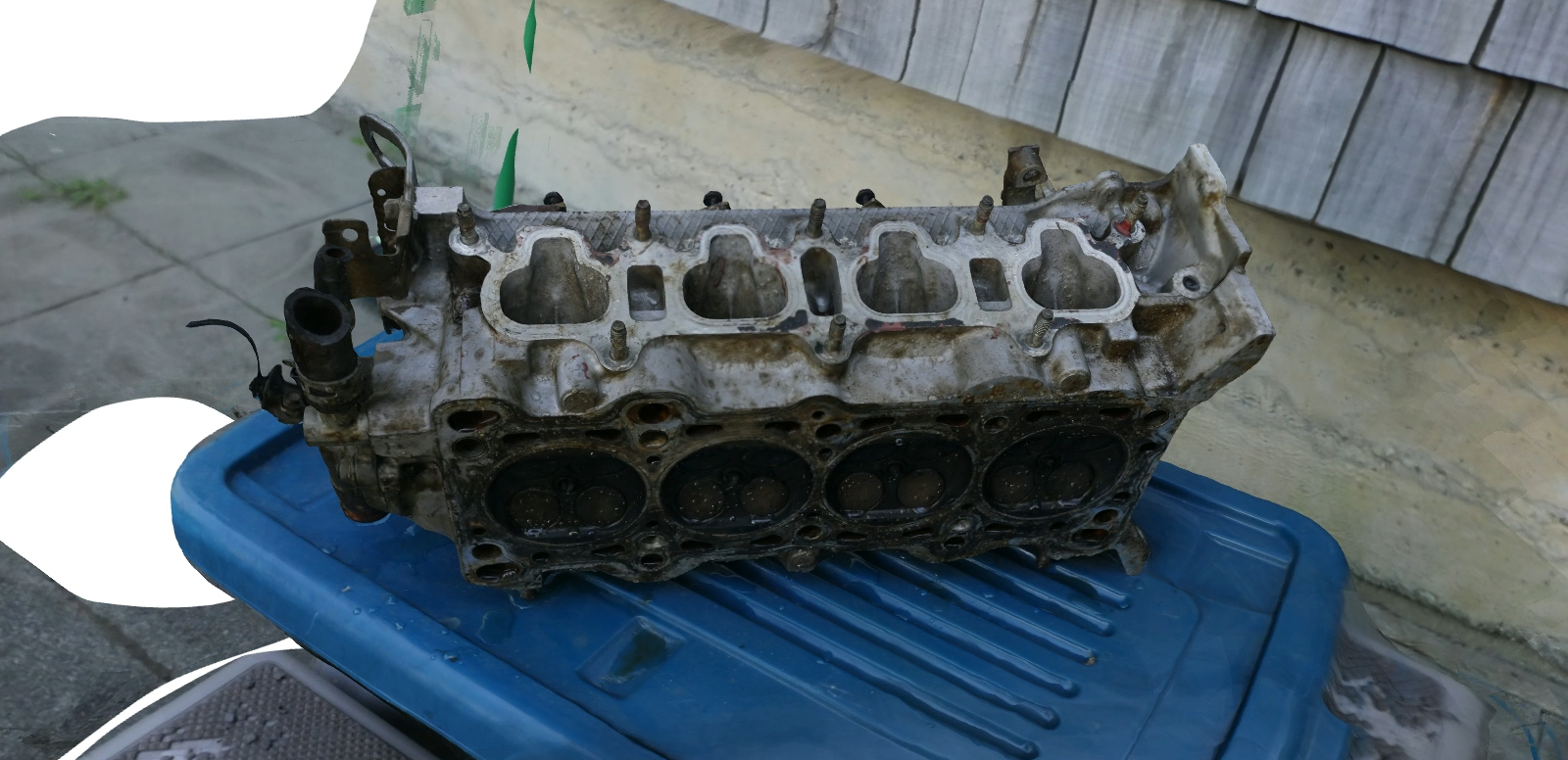
I've done a bit of bootleg porting with the air die grinder, but havent looked in to this. I know what you mean about the radius, I'll look in to it for the next iteration of the motor. I need to go pick up a spare longblock that has been at a friends house for far far too long, and will grab another head. This head pictured was my "spare" but the engine it came from was well and truly dead. Over 280kkms on the clock and there was damage to the head gasket in multiple places. I wouldn't run this one. I do need to pick up another head plus intake manifold to look at ways of re-manufacturing my intake manifold, I have ideas on how to modify one. I was playing around in fusion with better port transitions, straight shot etc. I need to look at how they angle the injector from factory, and how they deal with the separation between injector and the rest of the runner. I would put money on that transition being a big player for airflow.
-
A steady drive on totally private roads, for posterity. The tune still reeeeally needs a professional, it has a few big flat spots. https://drive.google.com/file/d/1Uy84HwzMM1ADAAT59gE432VnYk1q4Xfe/view?usp=share_link I also think the banjo bolt for VVT is rubbing on the bonnet, hence the flat spot and flaked paint... Oh well, holesaws make for pleb shaker hoods!
-
And to answer this, yes (compared to a b6). The port is quite a bit steeper, and larger cross sectional area. The valve angle is steeper (valve face is closer to parallel with the deck) and the intake port has less bowl, "straight shot" from intake manifold to valve. From what I've read, this design results in higher air velocity and more swirl in the combustion chamber resulting in higher efficiency from a complete burn. Contrast that to the bowl or "high approach" where you get more complete use of the perimeter of the valve, This is pulled from https://www.austincc.edu/wkibbe/headdesign.htm
-
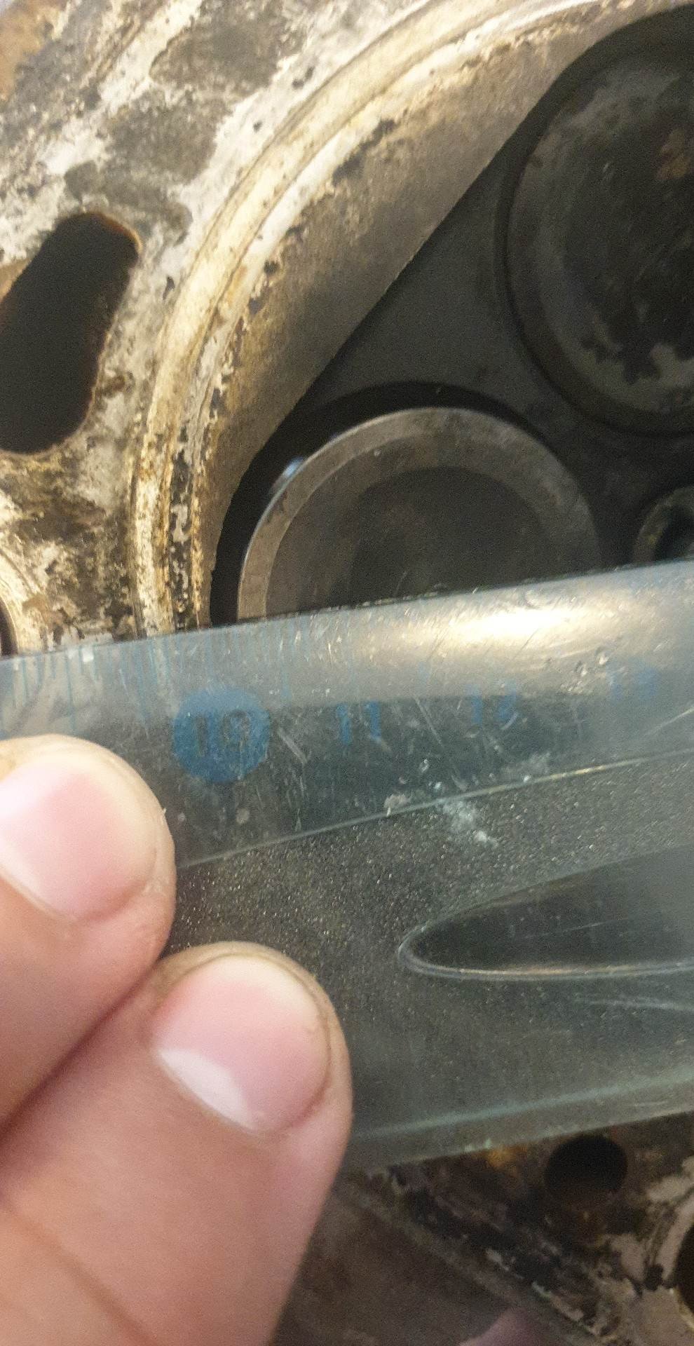
Good point, I guess I was just angry at the b6 having a larger intake valve! Yep after looking at this, that would definitely be an issue. Shit photo but the clearance is only about 1.5-2mm and any larger you would need to remove a significant portion of the head material around the valve. Even from factory they have made clearance in the head for the valve, you can see that it is slightly larger than the "round bore" of the head. Probably yeah. It is hard to know what exactly flows better, but this head does theoretically have a better port shape. I think just by looking at the clearance to the cylinder wall, larger valves might be off the table. Thanks for the input, I think it has been made clear that larger valves would be a losing game. Those 2zz valve springs and working on tuning and intake manifold would probably be better uses of my (lack of) money.
-
Someone asked, so I thought I'd just put it here for anyone in the future looking for this information. Units to the thousandth are micrometer measured, anything in the 1's is ruler. ZL-VE valve and spring information: Valves: Intake: 29.25mm head diameter 91mm overall length 6.00mm stem diameter 3mm tip length Exhaust: 26.00mm head diameter 91mm length overall length 6.00mm stem diameter 3mm tip length Springs: Intake: 42.50mm length 23.25mm outer diameter Exhaust: 42.50mm length 23.25mm diameter So yeah, smaller intake valve than the B6 by 1mm. Darn, not what the trustworthy internet had initially lead me to believe! I should have checked before installing the head but what can you do? FS-DE valves are 31.5mm, which look like they would fit... but it would be darn close! I might have to contact some engine builders and ask how feasible it is to put seat inserts in so close to the edge of the head? 32.5mm (FS-DE +1mm) would be a definite NO as the valve would actually start outside of the bore of the engine. Looking at some catalogues, toyota 3E motor in the tercel seems to have 31.15mm OD exhaust valves, 6mm stem and about 92mm total length. I need to get my hands on one! Why on earth did a toyota 1.5l have 31.1mm exhaust valves?
-
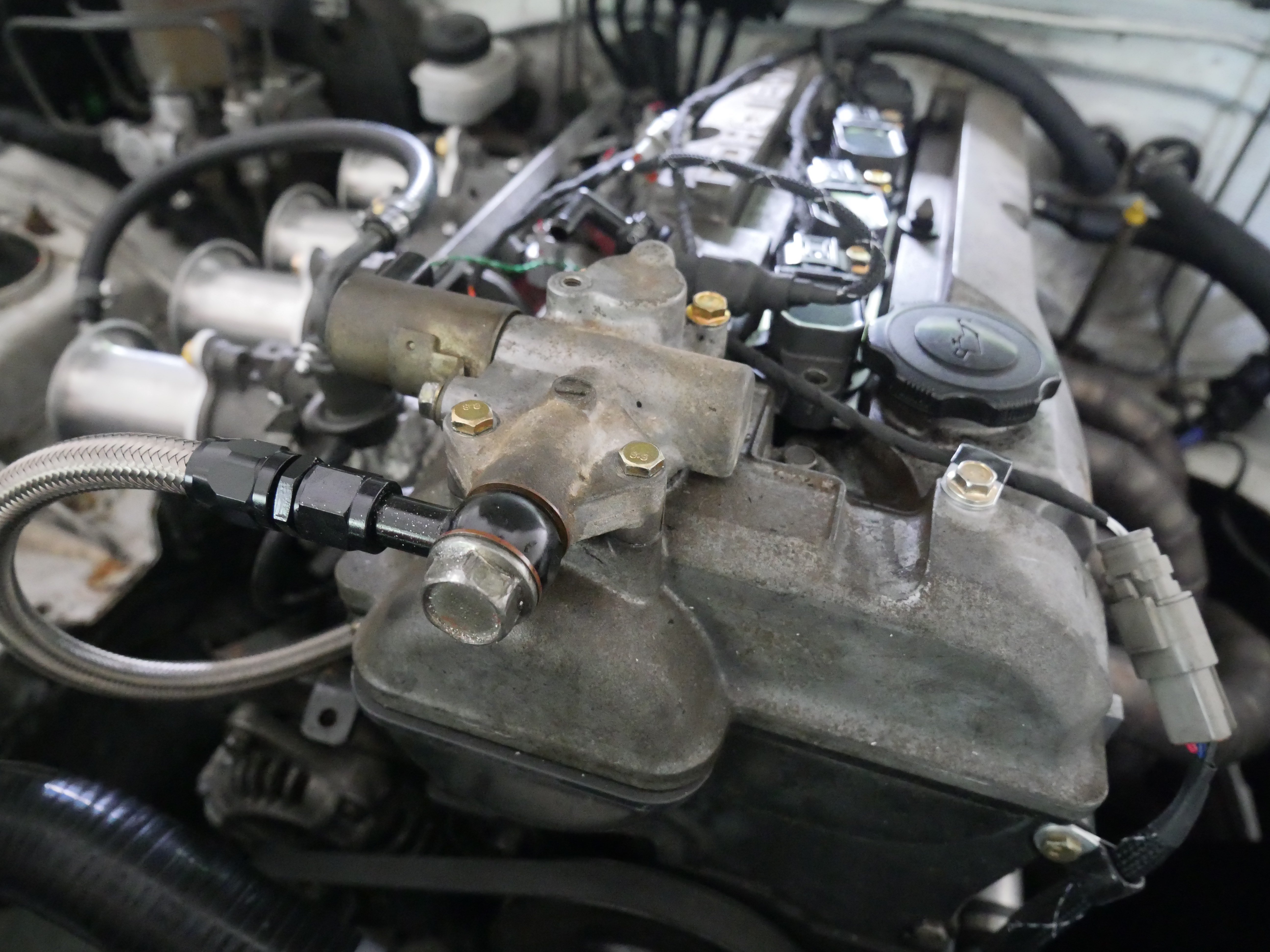
Sort of big news, sort of mundane technicalities. I installed the 36-2 trigger wheel I have had lying around for ages. In doing so I needed only a single tooth cam trigger wheel. I removed the rocker cover, made a cardboard cover and used an angle grinder to cut the two teeth off (pic taken half way through the process). I was very careful to have no metal possibly enter the head (there is blu-tack around the base of those teeth). Settings: Missing tooth 36 with 2 missing Single tooth cam trigger 190* ATDC primary trigger angle Rising edge (leading) cam/crank Weak filter Pic of setup (36-2 wheel shown for posterity). And pic of the 36-2 trigger beside my crank position sensor: I also got VVT working, properly and consistently! It was brought to my attention that solenoids such as the VVT actuator solenoid require flyback diodes. I added a 1n4004 right at the solenoid, and once that was working, VVT was almost perfect. A few tweaks of the PID values and it was mint! I need to re-pot the diode and connections into the back of the VVT solenoid but it runs very well, and the tune feels more responsive with VVT not just on/off like it was previously. VVT settings (only the important ones): Closed loop 300Hz Increased duty = retarded cam timing (backwards of the Miata 99-05 trigger) -159* cam angle PID: 0.81, 0.47, 0.023 Min/max duty: 40/60% (for now) I removed the engine strut brace as that needs tidying up, plus swapped VVT valve body(?) to the non-painted one, so that I can re-paint the other one.
-
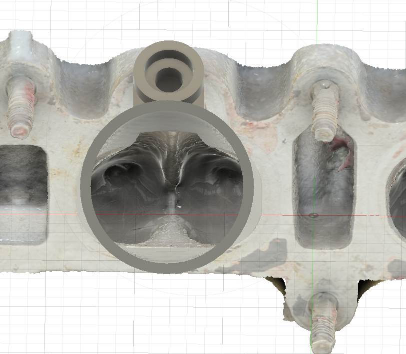
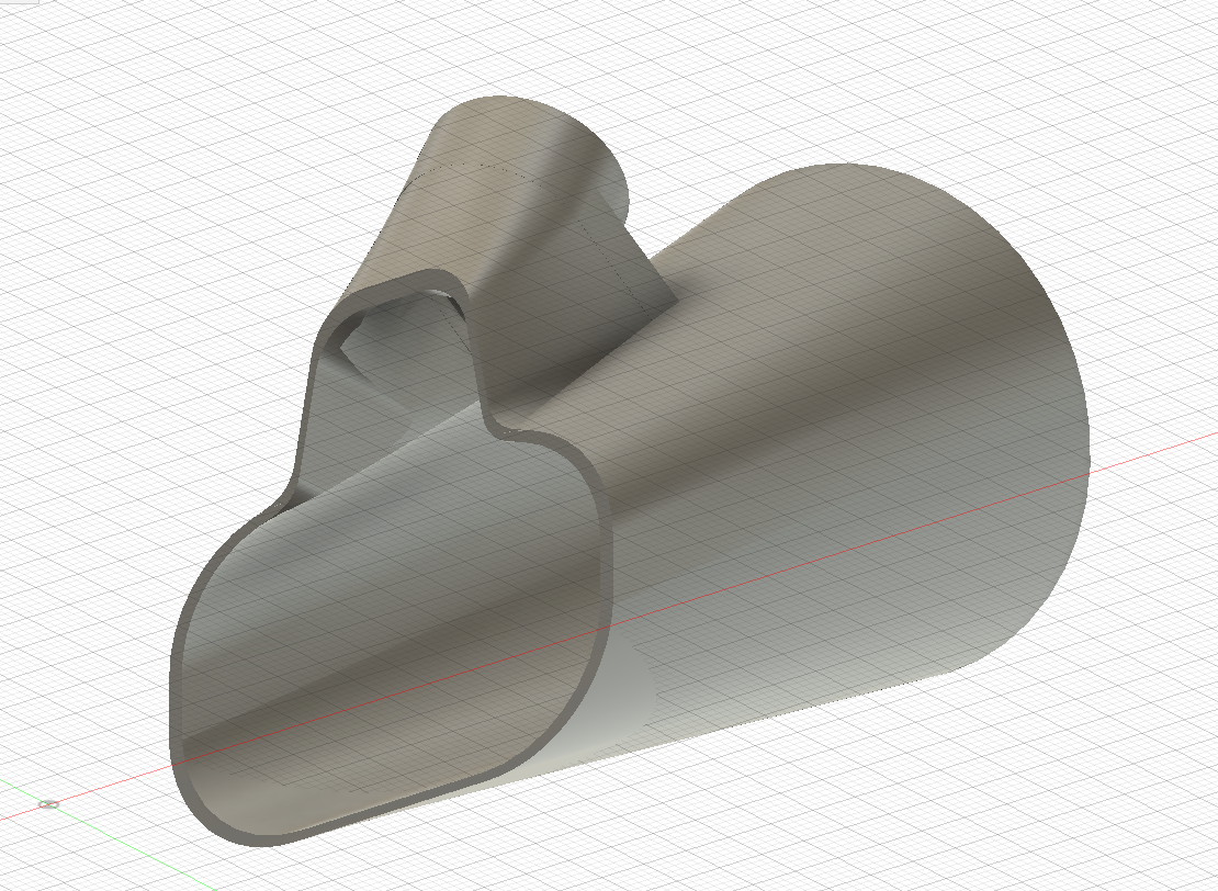
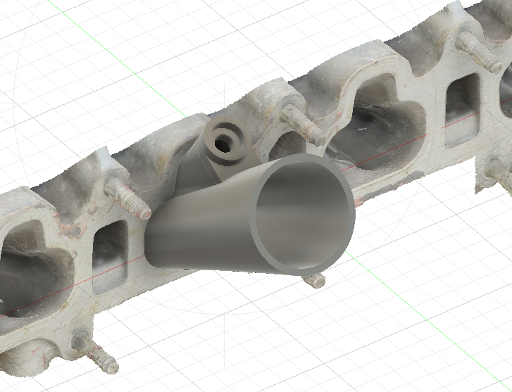
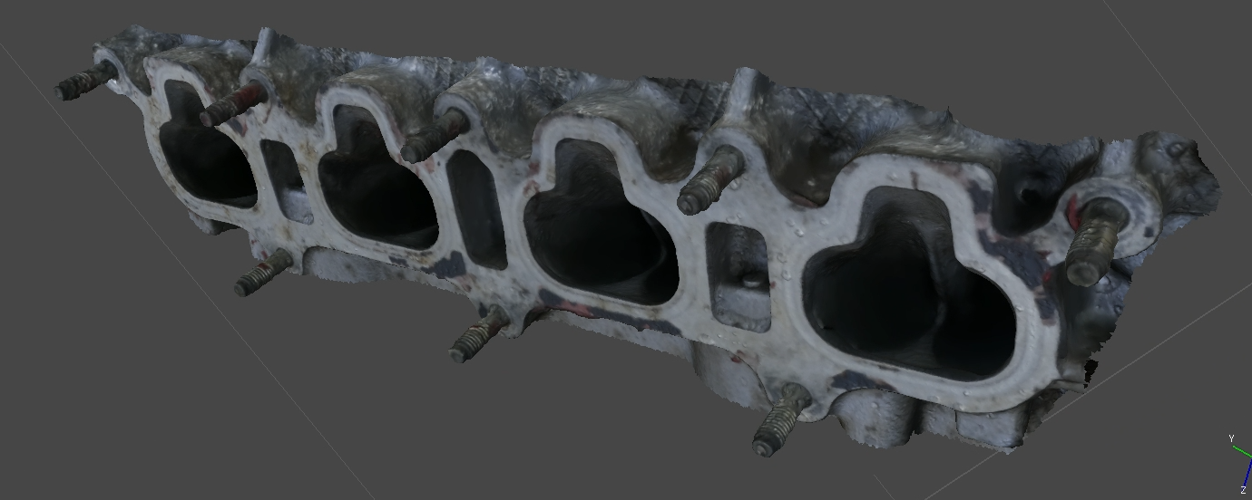
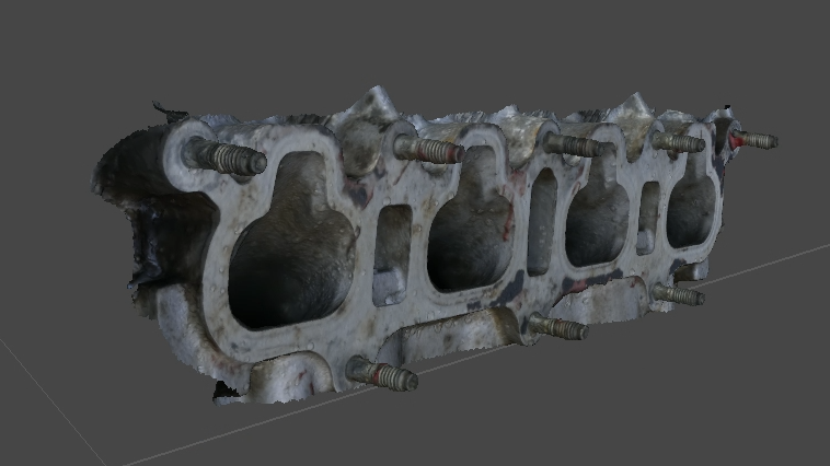
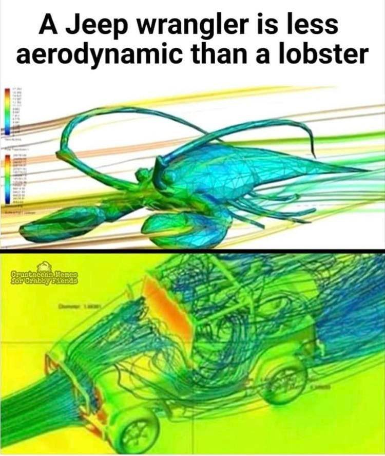
So I gave photogrammetry a try to start the CFD process, using two different tools. My camera settings were incorrect (ISO too high, and I corrected for lens distortion and chromatic abberation which the software will do itself) plus the head itself was wet. I had just given it a rinse off with some degreaser. A tip is that I did this in bright sunlight but under shade, so there was a lot of diffuse lighting in the area. You want the object evenly lit with no shadows for best results. Autodesk Recap Photo: Paid-only tool, which requires cloud credits (paid) to use. Students get unlimited cloud credits but suffer an extended queue. It took about 2 hours to generate this 3d model using the student queue. Honestly, it is far better than I expected. Agisoft Metashape: Also a paid tool (30 day free trial) but can process locally (Arrrh me mateys!). This took about 30 minutes to process, with some babying required. I believe Metashape is slightly less accurate than Recap especially on sharp edges, such as the transition into the port from the intake manifold (these get rounded slightly in Metashape). I chose Metashape over something like Meshroom as the support for openCL (amd GPU's) is better. This model I had already "cropped" away the environment and rest of the head to reduce edges as this was imported into fusion (worst tool for meshes...). Honestly, both of these are good enough for what I want. You can see on the closeups in the above image that even the water droplets are shown in good detail on the surface of the intake manifold mating surface. The stud threads leave something to be desired, but I think using this to model threads might be asking too much Anyway, in the next episode of this I will be modelling a port as a single body (not mesh) so fusion doesn't throw a wobbly. I will also make sure the camera settings are adequate and I will try to set up some white objects in the sun around this to increase the diffuse illumination especially at the bottom of the ports. I may also try the baby powder trick, dusting the inside of the ports with baby powder to make them brighter. I do also want to use photogrammetry on the car as a whole, run CFD on the mx5 and compare its drag coefficient to a lobster
-
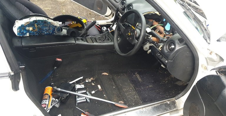
Found the short. A poorly modified door buzzer (I promise it wasn't me) had frayed wires, and was right behind the drivers side internal fuse panel. The ground was touching the wire which had a short to ground. All fixed! I did make the meet although stupidly did not take a picture of my car there. Tidied up the wiring over the coils/injectors also (finally). I think my to-do list now has dash gauges as the highest priority. I have speedo, fuel, handbrake, high beam and indicator lamps. Every other dial/warning lamp is inactive but should be used. Tacho won't be too hard, ecu has an output for that. Oil and coolant gauges will be tricky, I can either use the OEM sensor and run the wire to the dash gauge, or I could find a way of driving them with an external Arduino or similar. Fun future project? For now I plan to use a programmable output to control the "o2 temp warning" bulb if the coolant temp climbs above 92° (or below 0 indicating coolant temp error = no fans). Although I do have an oil pressure sensor, it doesn't seem to read properly and I think there is a wiring issue to be dealt to.
-
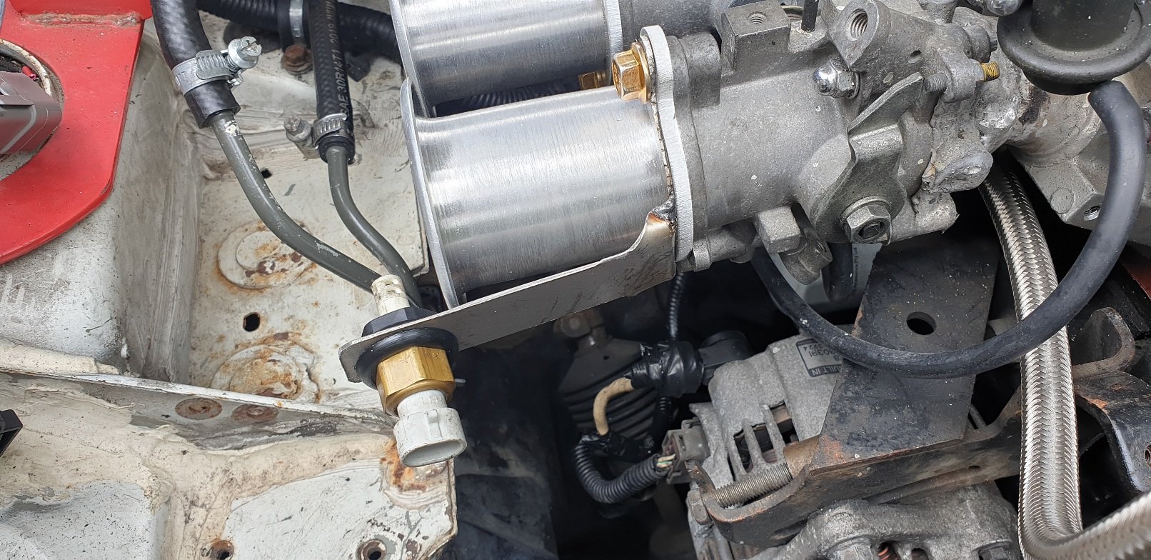
Sooo I made a bracket for the IAT sensor, so it actually reads intake air temps, not fuel rail temperature(?). Can you tell I'm not a fabricator? The one downside is now there is for some reason a short to ground somewhere up under the dash blowing an engine bay fuse... I verified what wire was shorted, disconnected everything and still shorted so it must be contacting ground somewhere along the wire. After fiddling, it is no longer shorted but I'm not sure why, which makes it harder to fix. I did want to try take this to the os meet tomorrow but that's looking like a more distant goal each minute. Seat and cluster had to come out for easy access, still awkward up under the dash.
-
Not a lot has changed I replaced the radiator hoses as previously mentioned (in early december?). I didn't touch it over the Christmas/NY break, although I have downloaded some photogrammetry software (recap) and will give that a go, trying to model a new intake manifold. I will throw some measurements up here, in case anyone in the future wants to know. Note: only the dimensions in mm have been measured by me (with micrometers). Any dimensions in degrees are third party, and will need to be verified in future. Intake cam duration 230° @ 0.003" Intake cam opening -3° - 32° BTDC Intake cam closing 53° - 18° ABDC Intake cam lobe height 41.50mm Intake cam base circle 33.00mm Intake valve lift 8.50mm Exhaust cam duration 240° @ 0.003" Exhaust cam opening 53° BBDC Exhaust cam closing 7° ATDC Exhaust cam lobe height 42.00mm Exhaust cam base circle 33.10mm Exhaust valve lift 8.90mm Valve overlap (Separation angle) 10°-39° (115°-98°) Note: Exhaust cam does have the tabs for a CAS at back of cam The stock Mazda B6 engine has only 7.8mm lift! This confirms my suspicion that the ZL-VE has bigger cams than the B6 did. Awesome. Pic of new radiator hoses (the aluminium tube slides all the way up to the 90* bends, so I can trim them back for a cleaner look later)
-
Use tape/paper/plastic to make a sleeve attached directly to the shock. Pour the urethane in place on the shock! No need for mould release, but if it doesn't work you would need to cut them off and make one hell of a mess.
-
Here is my thought process, looking at the speeduino firmware and doing some brain thinking (usually a terrible idea). This is an annotated version of lines 2232-2236 from github.com/noisymime/speeduino/blob/master/speeduino/decoders.ino //Record the VVT tooth time //toothCurrentCount = what crank tooth we have last seen. Values 1-8 for 4 tooth crank wheel over 720* cycle. //curTime2 = what time the cam tooth was last seen //toothLastToothTime = what time the crank tooth was last seen. // if (we have just seen crank tooth 1) AND ("current time" is greater than "the time that the last crank tooth was seen") if( (toothCurrentCount == 1) && (curTime2 > toothLastToothTime) ) { lastVVTtime = curTime2 - toothLastToothTime; // recalculate VVT angle } What I am hypothesising is that the VVT angle code for the miata99-05 trigger was written/tested only for the stock setup (i.e. crank tooth 1 passes the sensor at exactly 0*-ATDC). This portion of code is on an interrupt when a cam tooth passes the cam sensor, however the VVT angle is only re-calculated if the last crank tooth to pass the trigger was tooth 1. In my setup, crank tooth 1 passes the sensor 14* BTDC. Crank tooth 2 is 70* after that, so 56* ATDC. I believe at high RPM, oil pressure is high enough to push the cam as far into retard as possible. Crank tooth 2 passes the crank sensor before the proper cam tooth, causing the VVT angle (intake cam angle) to not be re-calculated. This means that the old calculated angle remains the same in the ECU. However at high RPM, the time between crank tooth 1 and cam tooth represents a larger degree of rotation (rpm increases = time between cycles decreases = increase of angle). I'll try recompile the firmware to temporarily accept toothCurrentCount as 1 or 2 to recalculate VVT time. I don't see any ill effects of this but it might solve my problem. Phew? Update: I've left the text there for future reference, but I solved this issue by changing cam/crank triggers and changing a few VVT settings. I never got VVT working on the miata trigger so it might still be a bug introduced when the cam/crank trigger offsets are modified like in my example.
-
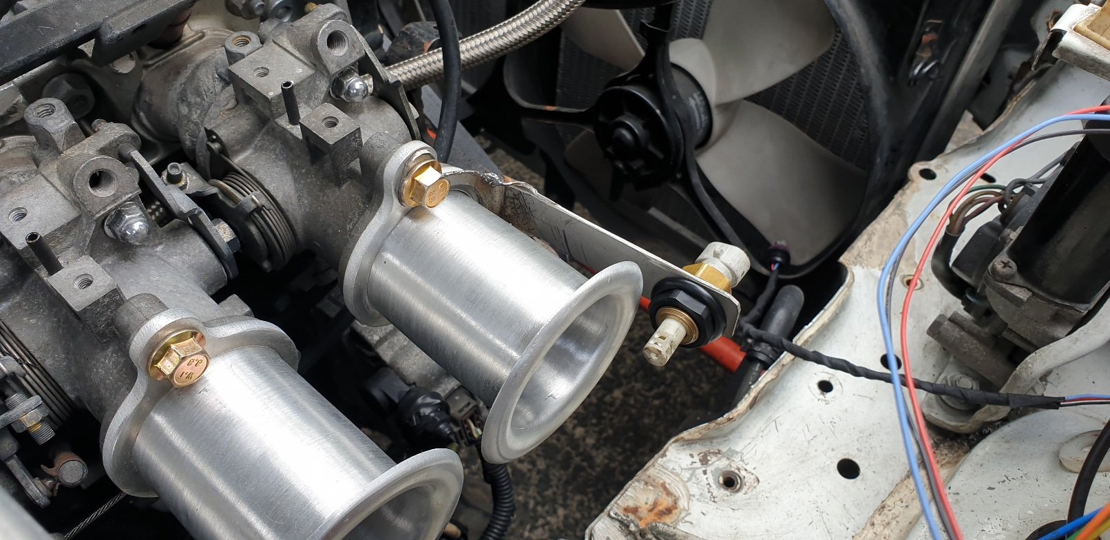
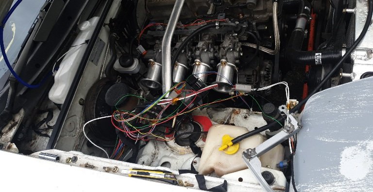
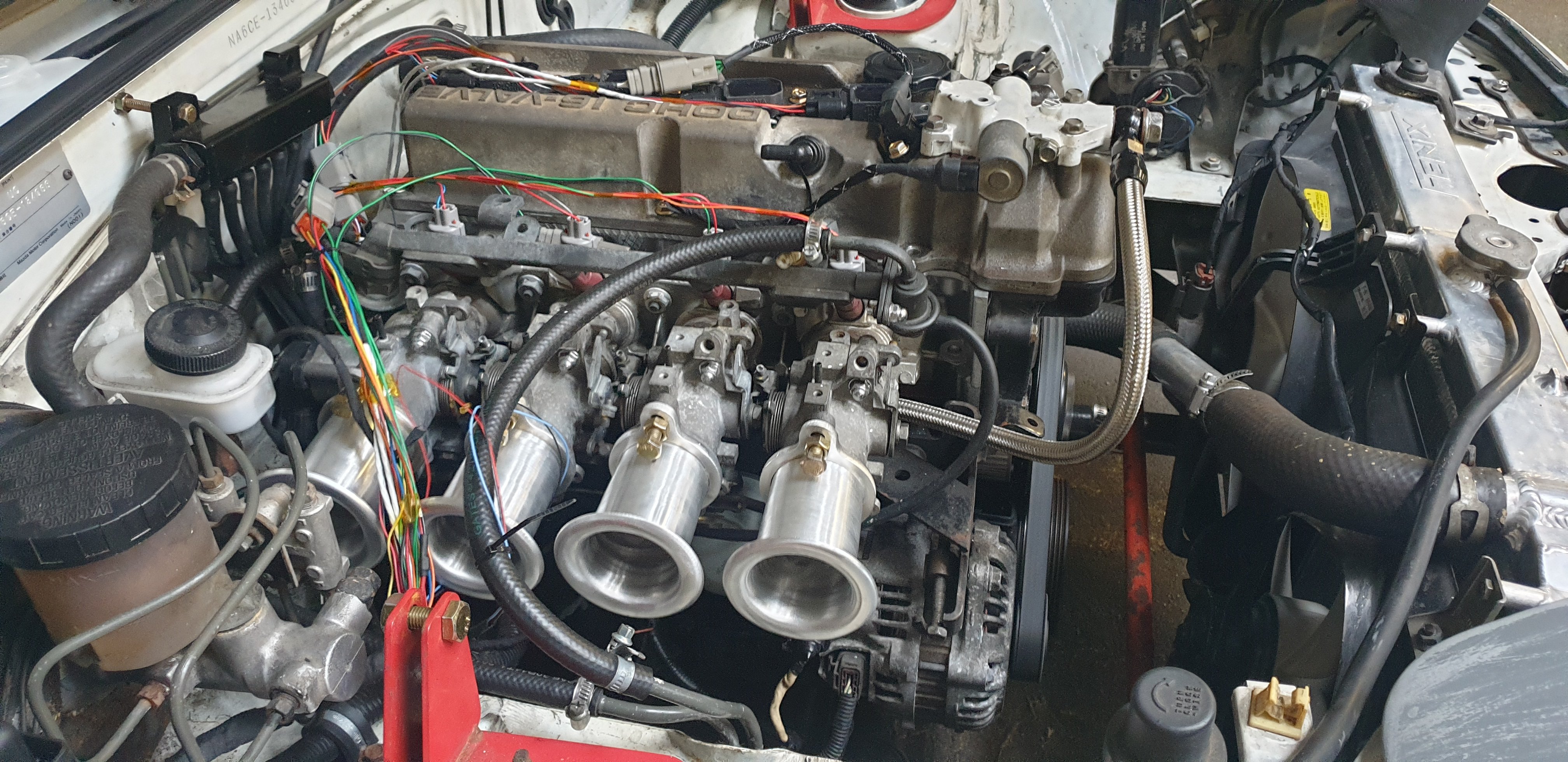
I'm running 3 core shielded wire from both cam and crank all the way to ecu, where the ground wires go to the ecu and shields tie together to ground (on ecu side only ). I do think interference could be an issue, no scope though. Maybe it should be an investment. Thanks for the advice Roman I'll keep digging. Pic with trumpets for interest. 970kms done on this head now. Also purchased a thermostat so temps go above 50 while cruising whoops. And some new hoses for the radiator setup, it is made of used and chopped rubber hoses right now.
-
They most definitely are, but the cam angle reading is derived from the difference between cam trigger and crank trigger angle. I don't know if PID would (could) mess that up. Odd regardless but I'll give the video a go to help me fix the pid
-
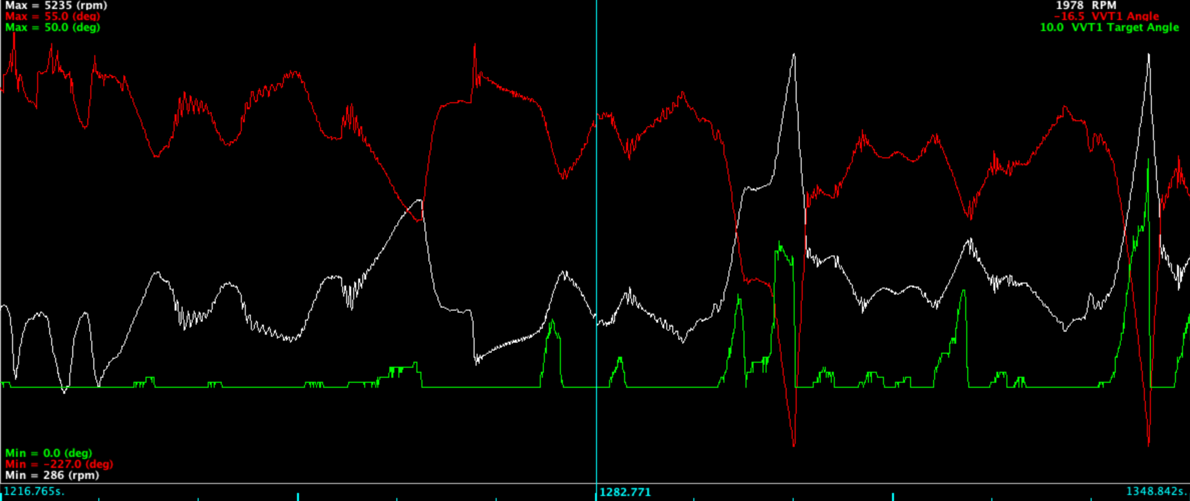
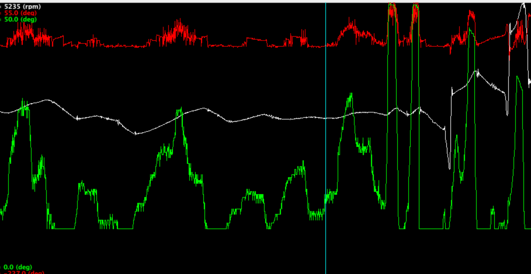
Hiccups! Here we see VVT target Angle (green), influencing the intake cam advance (red). As green increases, VVT duty increases (not shown) and the cam advances (red). White is RPM. In this image, we see cam angle (red) displaying as essentially a mirror image of RPM (white). This is not correct. I cannot even begin to hypothesise why sometimes each of these two scenarios occur, but it is a pain. As the closed loop VVT control does not work when the cam angle is out of reasonable range, I must operate as an on/off "vtec" style vvt. This definitely gives a bit of kick up the rear end at high load and medium RPM, but is not perfect. If anyone has a MS3 or speeduino running a late model NB with VVT, I'd love to hear from you about your wiring and VVT settings.
-
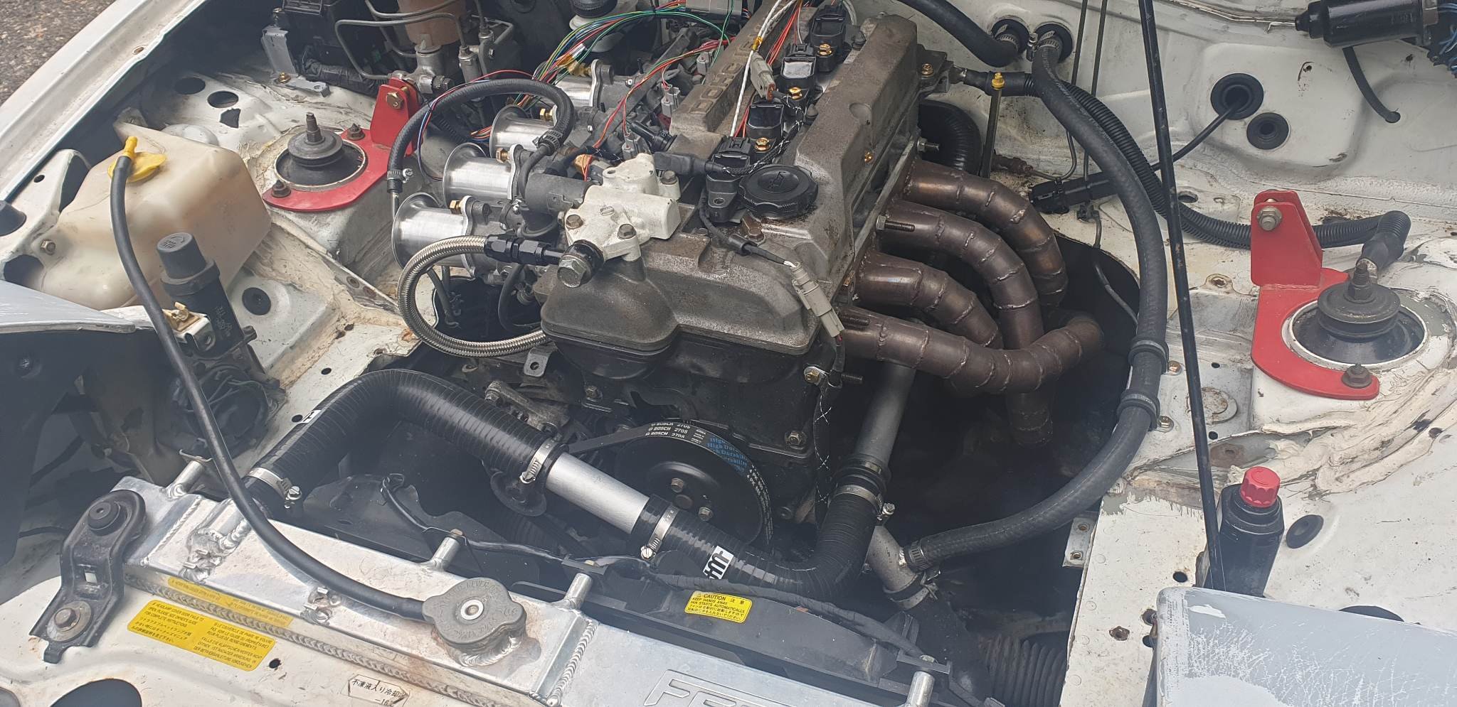
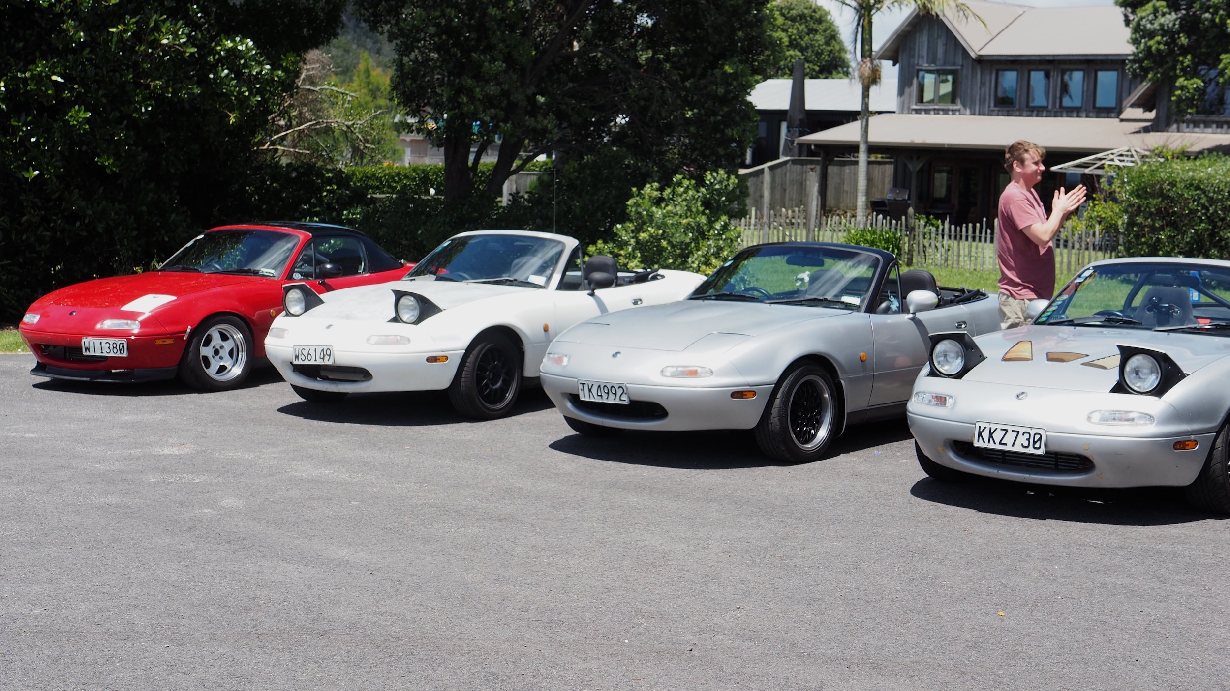
2 turbo (1.6 and built 1.8) and 2 ITB (both 1.6) mx5's got out to Hahei beach from Whangamata, great stretch of road to find redline on up and down the windy sections. First time the four of us have been in the same place since a meet at Kelly Tarlton's carpark in what must have been 2018 or 2019. My car did great, it really roars with the new trumpets. Downside is that it never got hot, and we are now assuming there is no thermostat in the back of the head oops! Another issue is that my throttles got very stuck and wouldn't return once opened. It turned out one of the adjustment grub screws in the linkage was loose, and tightened down on to one of the linkage tabs locking the throttles together. Due to my shit welding this misalignment was enough to hold the back two throttles open independently of the front two which was not good. We managed to fix it at the beach and made it back in one piece. Next thing to do is re-wrap all of the new bits of loom, replace thermostat, work out some sort of filter which fits the trumpets, and possibly get an undertray sorted. As it stands, there is a lot of area under the car which is open direct up to the throttles. All in all I am glad the car made it to beach hop, although it does feel like a fish out of water Looking forward to the drive home on Monday.
-
TL:DR is that it is great, and friends of mine swear by it (even for ITB's). My issue is that I am chasing a verrry intermittent misfire. 1 cylinder burbles a bit during idle and sometimes under acceleration. This I believe is either a vacuum leak on a single cylinder, or they aren't properly synchronised (could also be injector imbalances). Misses read lean so autotune pumps more fuel in. Additionally, a feature I would like added to the autotune is for it to not correct cells if acceleration enrichment is running. Currently under TPS smashing the car is a bit rich and leans out the cells, but if you are static in that cell (say going up a hill with a steady throttle) it will then be quite lean. Whereas if you tune it yourself you can ensure you are only seeing data from the logs where acceleration enrichment isn't happening. Finding the actual AFR during static loads and do the "autotuning" yourself. Admittedly if you are a sensible driver, you can be very gentle on the throttle and autotune will work great
-
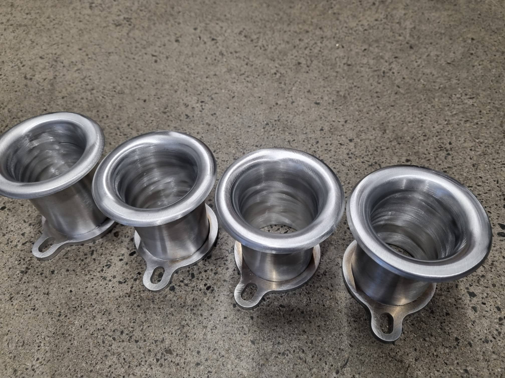
Also, thanks for the support! Glad someone else is getting value from my work It's only fair given the inspiration/knowledge I get from your builds too! Sneaky pic of the trumpets just sent from the fabricator...

.jpg.f6247005b4012672e377fe22ae206390.jpg)