Hurmeez
-
Posts
341 -
Joined
-
Last visited
-
Days Won
1
Content Type
Forums
Downloads
Events
Gallery
Everything posted by Hurmeez
-
I got my axles back from the machinist for an unbelievably good price so I can start getting them set up to go back into the diff. I made a start by pressing the brand new bearings on. A handy thing about the skyline axles is they have identical bearing faces to the Falcon axles I got rid of out of my housing. So two brand new Falcon bearings later and I have a fully together diff and a rolling chassis once more. Next, I threw my mockup brake setup on. I quickly noticed a problem when I went to bolt the wheel on. The caliper actually sticks out further than the wheel mounting face. I'm not exactly sure how the Mondeo wheel looks, but I'm getting the idea that it must have a bit of offset with a mounting face the same diameter as the brake disk. The Cheviot Turbos that I have have a mounting face that is bigger than the brake disk face, so it doesn't sit down properly. My best solution for this is a 10mm wheel spacer. I made a mockup out of MDF to test my hypothesis. According to the Hobby Car bible, this would meet almost all the requirements of a wheel spacer. It also has the bonus effect of making the wheel hub-centric, because the turbos have a larger center hole than the standard Escort sized hub spigot and are do not transfer the load to it on a normal English diff. The only thing I'm not sure of is the requirement for the spacer to "be set-screwed or attached by another secure mechanical method to either the wheel or hub face." Does the fact that it is clamped by the wheel nuts not cover this? Or would I have to drill and tap countersunk screws into the mounting face of the wheel to ensure they are compliant? In any case, I threw the mockup spacer on to check fitments. Here you can see that it provides a mounting face with sufficient clearance to the caliper. And the hub centric support: In the final version, I would probably make the center a blind hole that sits snugly over the axle spigot for extra support. And finally, the wheels fill out the arch much better in my opinion with just that 10mm extra track width per side. And with the center caps on, you'd never know the difference. While typing all this, I had the thought that Mondeo front disks may have a different offset between the braking face and wheel mounting face which may solve this whole thing. It wouldn't solve the hub concentricity issues though. I think I'll still go to the wreckers and have a look but I'm open to suggestions. Cheers.
-
I wasn't completely happy with using bolts with each mounting flange being tapped to hold each throttle body on. Not least because all my untamed strength acting on the quarter inch ratchet managed to strip one of the alloy tapped holes on the first try. So I decided to swap the whole lot for steel studs pressed in from the back side of the flanges. So, two minutes of turning later... You get these delightful little fellows: And then pressed into place. Which gives me a much more professional looking nut rather than bolt with a neat little button head on the back. While I was in there I also added an extra throttle return spring. I'm much happier with the throttle now. I wasn't quite returning to its seat after lifting from light throttle but now it snaps shut far more satisfactorily. Next job is at the other end of the car...
-
So with the idle circuit sorted, I figured after working on getting a little bit of air into the engine, the next logical step is to figure out getting lots of air in as well. I'm not sure if I've mentioned it before but I plan to use the original BMW linkage rods to actuate each TB. They are stainless from factory and hard as a coffin nail, so I'd really like to avoid machining or drilling them as much as I possibly can. Because I basically can't. So I won't. I actually considered this way back when I designed the intake flanges, spacing them out the same as they would have been on the V10 in the first place. This meant that all the cross drilled holes in the link rods already line up with the throttle bodies and I can use the factory linkages and everything is peachy. Also, being originally off a V10, the rods were too long for the banks of three per side that I'm using. This left me with a handy little overhang on which to mount a custom eccentric throttle wheel. So with the help of @yoeddynz once again, and a little bit of maths, I designed this: Using the standard Escort's pedal throw of ~46mm, it gives you a little over 1/3 (7/18ths) throttle opening at half total pedal throw and the remaining 2/3rds ish with the remaining travel. Hopefully this strikes a good balance between fine controllability and spongy pedal feel, like you get in so many modern fly by wire setups. Unfortunately I won't be able to know for sure for a very long time, but, such is life. Using that neat little drawing, I spun this up in the lathe with the four jaw chuck. Probably the most offset job I've ever done. Thought the bloody thing was gonna jump out at me any second when it hit its resonance. Here it is mounted on the link rod: With that done, the next thing was to make a bracket to hold the throttle cable. I'm using a standard Escort throttle cable shortened by about 150mm and with a late model style barrel end on it. This lets me use a standard pedal and clip and not have to worry about modifying anything on that end of the deal. Here is what I came up with for the bracket: It is made from 2mm sheet to match the original bracket. This means the clip system on the end of the throttle cable fits in snugly. As you can see it is mounted to the idle circuit tubing. And here it is in place: And full throttle: Finally, I had to connect each bank together. I ordered some rose joint rod ends from china with a left-hand female thread, and repurposed a right-handed example from my original twin carb setup for the Pinto from way back. Then I modified a pair of the factory linkages to be parallel at half throttle but with one above the rod and one below, while still picking up the original holes in the link rods. This should mean that each rod should rotate at the same rate but in opposite directions for the entire arc. Finally, each rose joint is connected by a stainless steel rod with opposite threads on each end to allow for fine adjustment of length and to balance each bank properly. I also made up a couple of lock nuts for each end. So finally, this is how it all looks in action from the driver's seat: With that all done, while I was in there, I installed the proper vacuum rated flexi hose for the idle circuit. Looks flash as now. Not sure what the next job will be but I'm sure it will end up on here at some point. Cheers.

-
Man I almost missed the engine jamming out too hard to those sick beats! I wonder if Kelford would be able to regrind the standard cams to an even more aggressive profile? I'm glad I bought the DE engine first now so I can swap in the reportedly superior valve train components.
-
Interesting how he was saying that it has a 7k redline. For some reason I had it in my head that it was more like 8 but I'm not sure where I got that from...
-
Also that video is awesome! Didn't think I'd watch the whole thing on data but next thing I know the whole things gone by. It sounds heavenly up in the revs!
-
You know, I knew all of that already but I never put the fact that you could wrap the throttle cable around the pulley as much as you like and it's still only going to pull it through 90 degrees if you've got the radius of the wheel right. The fact that yours was wrapped almost half way round was really messing with my head. Thanks for explaining it so well.
-
Each bit you do is one bit less at the end of the day. She'll be sweet when she's done!
-
Awesome! I'm gonna be off it for a year while I'm on a course in Auckland so progress will come to a screeching halt for me.
-
You'll definitely have yours done before me so it'll be interesting to see what you find.
-
It's a shame they didn't make them for the superior cylinder arrangement really! Would have made my life a little easier. I'll have to send a strongly worded letter to Berlin next time the pony express comes through.
-
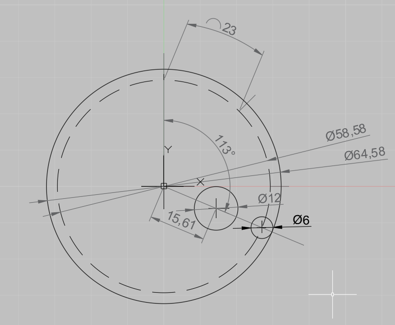
Moving to the Throttle bodies, I decided I'd start with the idle air control circuit. Originally I planned to drill and tap some brass fittings into each intake runner and join them all with push on vacuum line to a central ICV somewhere hidden away. That would then require me to plug the BMW injector ports (I'm going to use the standard Mazda V6 injectors) since they are on the vacuum side of the butterflies and would pose a significant vacuum leak. Then I had an idea. Well @d.p.n.s had an idea and it was pretty smart so I thought I'd take the credit. If the BMW injector ports are going to create a significant vacuum leak, then why not use it to control the idle? Dan got lucky with a set of throttle bodies that already had a ICV setup on them and all he had to do was cut and shut it to fit. Unfortunately, for whatever reason, the V10 style of throttle bodies (Which I am using) don't have one built in. So I'd make my own using the unused ports. I started by machining up some "false injectors" out of mild steel. I considered stainless for the bling factor but the extra pain in the butt I'd have with the machining made me reject that idea. As you can see, they use the standard O-rings and are shaped essentially identically other than the long injector nozzle. Here they are in place: Then I crossdresseddrilled each one and ground them out to shape to fit a common balance tube. Which they were all then welded to. I put a cheeky little cap on the front of each one at a jaunty angle to make them look a bit faster. Next was a couple of little brackets to hold each new false fuel rail using two of the throttle body mounting bolts. So now I have two separate balanced banks of throttle bodies. Next I need to connect each side together to balance the whole lot together and hook the whole lot up to an idle air control valve of some description. Again, Dan's throttle bodies came with their original IACV but mine didn't. So I did a little research and found that there are an awful lot of BMW engines that use the same model of IACV, including a couple of six cylinders that were down at the local wreckers. So $30 later I was back with a nicely gummed up and seized valve. A bit of brake clean soon had it cleaned up and freed and I started looking at options for hooking it into the system. The first thing I did was try a random brand new filter I found in the empire of dirt. What do you know? It fits over the intake perfectly! Magic! Then I wrapped it in a strip of sound insulating sticky backed foam which you can see above. This is a little too thick for the final fit but I carved it up to fit for now. Then I found a random ignition coil mounting strap and again, it fits perfectly! A study in serendipity this is turning out to be! With the mounting sorted, I continued by machining a few different fittings to assemble into this T-piece, among others. I intentionally made all these custom pieces the same dimensions as the output side of the valve to keep all the hose runs easy and not have to worry about diameter changes along the way. That then gets welded onto the passenger side false fuel rail. (I suppose balance tube is a better name actually) With everything bolted up, you can see the short run for a piece of vacuum rated tube to connect the valve to the balance tube. I also welded a fitting to the other balance tube to connect them up. I intentionally made this one the same length as the T-piece to give me the option of welding another tube on underneath for a brake booster vacuum source later on if I decide I want one. Finally, I connected everything up with a piece of hose I had lying around. I don't think it is vacuum rated at all, (it's pretty easy to squash by hand) but it looks good for now and I've got some proper silicone hose on order from the parts shop in town. I'm going to start on my eccentric throttle wheel next but I'm struggling to figure out the maths behind the radius, versus center offset and so on and so forth. At the moment my thinking is that a throttle butterfly only opens by 90 degrees or a quarter turn, give or take, from closed to full throttle. Therefore, if I find the full travel distance of my cable and multiply by 4, that should give me the circumference of the wheel. Then I was going to decide on how far to offset the centers by looking at pictures online, but of the ones I've been able to find, none of them seem to have the cable pulling the wheel through 90 degrees. Most look more like 120 degrees and I mean, @yoeddynz's one on the old Viva looks like it wants to pull through almost 180 degrees and that doesn't make a lot of sense to me. If anyone can help me out with any advice in this case then I'm all ears. Please share any ideas or advice here: Also I just realised, I never properly showcased the finished intake runners with their flash professional welds. Hopefully these photos do enough to show off how pretty they are.
-
The next job was to get the diff mounts sorted. I found some suitable box section and carved it up into something resembling a diff mount. I copied the original Escort pads in pretty much every way to make sure they'd fit the standard springs nicely. Then I welded up the original holes in the shock plate/spring mount and redrilled them further apart to take the bigger Falcon U-bolts. I bought a new set of springs for it a while ago because I thought mine looked pretty shagged. They were making a W shape rather than a U when there was any weight in the back of the car. So I threw them in and it bolted up, set all my angles, and jacked from the centre section to see what ride height I'd get from the new springs. Just to prevent any confusion, that is the car sitting on bump stops. With no weight to speak of in it. With my new springs. Yayy. So I had another look at my original springs. It turns out they'd been subjected to the ole' flipped leaf, hence their W shape. So I disassembled them and put them back together in the right order and swapped them back in to find that they gave me a ridiculous monster truck ride. So I swapped the centre leaf of the original spring for the two centre ones out of the new set and tried it again. That finally sorted it out. I didn't actually get any photos but I think it's something like a two-inch drop from stock. It did come with a whole new set of problems though. Measuring the angle on the gearbox output shaft gave me an angle of 8.5 degrees down. So I set the angle on the input shaft to 8.5 degrees up at ride height to make sure the drive angles were equal and I'd avoid any vibrations etc in the U joints. Then I measured the angle of the driveshaft itself and got 2.5 degrees. This means the U joint angles would come to a total of 6 degrees. Now everywhere I've looked online says that 10 degrees is the absolute maximum you want to run on a driveshaft U joint but anything less than 5 degrees is far more ideal. Now I wasn't completely happy but I was willing to just run it with the 6 and hope for the best but there was one other thing that meant I forced myself to do something about it. With the engine at its current angle, I was going to have a clearance issue between the front passenger side throttle linkage and the bonnet. I worked out that if I were to raise the gearbox cross-member by ~50mm, it'd put the driveshaft angle down to something closer to 4 degrees, as well as getting ~10mm of clearance for the throttle linkage at its closest point. The only other option would be to drop the engine down. But I've already go it as low as possible with the standard cross member and any more and I'd have to start modifying the steering rack mounts and suspension geometry and that's a huge can of worms that I have absolutely no intention of opening. So next job was to make a riser for the transmission tunnel. As per, I started with a CAD template, Then steel, Welded in my original boot mounting ring, Tacked it, And welded it. I reckon with a custom centre console and a standard looking vinyl shift boot, I can cover the whole thing and still have it looking fairly standard. Finally I made a new gear box cross member to lift it up into its new home. I'm much happier with this one. Here you can see just how far I've raised everything by the difference in cross members. Still no rear axles though so I can't fully and finally sort out the diff mounts and rear brakes yet. That's it for now. I'm planning on working on the throttle linkage and pedal setup next.
-
I started thinking months ago about the diff in the car and whether or not it'd be able to stand up to the extra power. I'd read in many places that they're good to around 200 horsepower if you are gentle on them. However, I plan to have a little over 200 and I have very little intention at all on being gentle on it. So I started looking at different options for an upgrade. I looked down the Hilux route for a while but I was struggling to find one. I then read up on the BW78 as found in @Rhubarb77's turbo pinto Mk2. Coming standard in Falcons and Commo's for decades and being a popular swap over the ditch means that there's heaps of information available on them, as well as aftermarket LSDs options, and so on. So I went down the road to the Zebra and pulled a housing out of an AU station wagon. This was the best option, other than a ute, because it had the least useless brackets and linkages for me to cut off as compared to the four-link bars and Watt's links on the sedans. I also pulled a center section out of an AU XR6 for the LSD and 3.45 ratio. That's much better than the 3.23 that was in the station wagon diff and will put me right about 2500 rpm at 100kph. All up I think it cost somewhere on the thin edge of $200. I also found a set of axles from an Aussie assembled R31 Skyline. They have the same splines and bearings but are four stud and shorter than the Falcon axles so better for shortening. Both the Falcon and the Skylines have different length axles side for side to put the input flange of the diff in the center of the car. This is another thing that makes it easy to shorten them. By putting the short Skyline axle on the longer side of the Falcon housing and shortening it to fit, then shortening the long Skyline axle by 125mm and the housing by the same, I could get away with only modifying one axle to save time and more importantly money. I ended up with something like this: I got it done by Lee at Diffs R Us. He also tightened the LSD up to the best a standard cone type can possibly be while he was there. I was over the moon with the result and would recommend him to anyone. This is a comparison shot to show the difference between the Escort and Skyline axles: I shouldn't have to worry about snapping one of these puppies. Especially considering the fact that I'll be lucky to get a maximum of a 205 profile tire under the back. Next thing I wanted to sort out was the rear brakes. While we were in the wreckers to up the diff, we noticed a Mk2 Mondeo. It had 4x10⁸ stud pattern, vented rear disks, sliding single pot calipers, cable handbrake, and it all fit under 13 inch rims. They looked perfect. So $60ish later I got them home and started working on making them fit. The first thing I found was the central hole in the disk was too small to fit over the spigot on the end of the axles. Initially, I considered embiggening the disk to fit the axle. Then I realised the disk would be a consumable part, albeit very rarely needing to be replaced. With that in mind, I opted to spin the spigot on the axle down to keep the consumable parts as standard as possible to save headaches down the road. With that done and the disk fitting snugly, I started figuring out a caliper mount design. It came down to something I have to give full credit to the old man for. The one issue with the Mondeo caliper is the mounting bosses are well offset from the actual disk itself. This made them difficult to pick up effectively with a bracket. So we thought outside the box. It's made up of two plates. One that picks up the axle retaining plate bolts, just as the standard Falcon caliper mount did. Then a series of spigotted spacers support another plate which the caliper then bolts too. The cardboard above represents each plate and the spacers are currently imaginary. I ran the design past the certifier and he said he was more than happy with it so it was full steam ahead. I cut the plates out of 6mm steel with the gas then started putting holes where there needed to be less steel. I turned up a wooden spigot to hold each plate true to each other while I drilled them to absolutely ensure the holes would match. Next, some temporary wooden spacers were made to prove the concept. That was where I ran into a wall. The next job is to make the spacers for real. To do that I need the axles in place with bearings to confirm the disk location. The problem is, I don't have the axles at the moment. Even though the axles are four stud, they are 4x114.3 rather than the 4x10⁸ that I need for the Escort wheels. To remedy that, I welded up the flanges (legal in New Zealand I was glad to find) and sent them away to get restudded. I made sure I preheated each axle and welded them up as hot as the poor little welder would suffer, before leaving them in the gloven to slowly cool off again and prevent any unwanted hardening. When I refaced each axle, the welds weren't much different in hardness than the rest of the axle so I was more than happy with that. So now, as I mentioned, I'm waiting on the axles before I finalise the brake mounts. Still plenty to do though...
-
I'm loving that Ramflo idea! I might look a bit further into that...
-
@fuel I did consider a cross ram style intake but as @yoeddynz said, the port spacing made it difficult to fit the runners between each other, especially with the 50mm tubing I had to work with. It is a shame cause they're a great packaging solution and look great too! @Transom I didn't realise that about the vent tubes. You're exactly right about the pcv being directly under a runner on the other side. I was going to come up with a custom tight radius 90 degree bend to fit it but if I could just plug it and use the driver's side vent then that'd be a lot easier.
-
In the meantime, I've been working on the repairs to the driver's door. You may remember this mess: While I'm all for the sleek look of no mirrors, perhaps this wasn't the best way to go about it. I started with a rough cut out from a paper template. Using a series of small folds in the brake, I formed it to match the shape on my dad's untouched MkI before trimming to fit. I got it tacked in place with minimal warping. Then very slowly I fully welded it. I'm no panel beater but I gave it a tickle up as best I could and I'm fairly happy with where I've got it. It's quite clearly miles better than where it was. There's still one or two patches that I want to make up but I'm happy with the progress. I'm working on something totally different at the moment but I'll wait until I get a bit more done before I show anything. Cheers.
-
I had no idea it had been a whole month since the last update. There hasn't been a lot of solid progress in any one place but there has been lots of small progress in different mini projects. Firstly, I got the intake situation all pinned down and finalised. I actually fairly radically changed the layout and turned the whole thing on its head. Literally. To start though, I cut what was left of the original manifold down even further, before making up some transition pieces out of the 50mm tubing I've been using, and tacked them into place. The welding on these more heavy materials isn't so difficult but once I moved on to tacking the donut sections I really started to struggle. That said, I persevered and got two manifolds fully tacked and bolted on. You'll notice a couple of things. Firstly, the throttle bodies are now the other way up to how I originally had them. Second, the right-hand bank has two sections of donut to make up a single bend. That was because when I decided to flip them all I realised I didn't have enough left of the donuts to do it out of one piece anymore, thus, two bits. As for the reason I wanted to flip them in the first place, doing it this way gives me twice as much room for air cleaners/trumpets on the passenger side bank, (forgive the paint stick rule) as well as clearing my original clutch reservoir position, while still clearing the valve cover vent on the driver's side too. It's going to be a little close between the throttle linkage on the passenger side and the bonnet but if that's the only issue then I'm a very happy camper indeed. One last beauty shot from above, Before I sent it away to get fully welded. While I'm sure with enough time and perseverance I could have gotten everything stuck together in a way that would hold water, the money I would have spent in replacing the donuts I rooted in the process would have quickly outpaced the cost of asking a professional nicely to do it. That and the fact that it's such a central piece of the visual puzzle under the bonnet, I'd rather pay for some stacked dimes then make my own bird shit. Hopefully it won't take too long. I'll be sure to show it off once it's back.
-
How do you deal with the engine moving around on its mounts with a bonnet sealing box? Do you just use really thick cushy rubber to line the sealing edges?
-
Those trumpets look very smart! Are they just a slip fit onto an O-ring? What are your plans for filters?
-
How did you end up doing the remote booster setup? Did you use one booster for each circuit or is it just the front brakes that are boosted? I am planning on doing a similar setup in my car and I'm trying to figure out the best way to go about it. Cheers
-
That's a good idea actually. I'll have to look at it a bit more.
-
I see. That's interesting, perhaps the V10s are slightly different to the I6s because I don't remember any other ports on the body. I'm planning on drilling and tapping some small barb fittings into the runners and plumbing them into a fabricated reservoir that sits on top of the injectors. It should look good and cover up the plastic tops of the injectors. I think I'll put a frost plug type bung in the standard injector port.
-
Are you using the standard injector ports for your IACV and vacuum reservoir? Thats a good idea that I hadn't considered. How are you holding them in and stopping them from popping out in the event of a backfire? Looking really good so far!
-
Keeping notes is always a good idea in my experience too. I've got a whole clear file full of receipts and details about which parts I've used and what wrecker car they've come off and so forth. Should be invaluable when the gearbox mount wears out or I need a rebuild kit for the brakes or what have you. I actually found a neat little cardboard number wheel from BOC in the empire of dirt the other day that tells you what amps, filler, gas, travel speed, dip rate etc. etc. to use for a bunch of different material gauges and types. It's bloody handy but now I have to figure out where the safe place is that I saved it.