Kimjon
-
Posts
2181 -
Joined
-
Last visited
-
Days Won
1
Everything posted by Kimjon
-
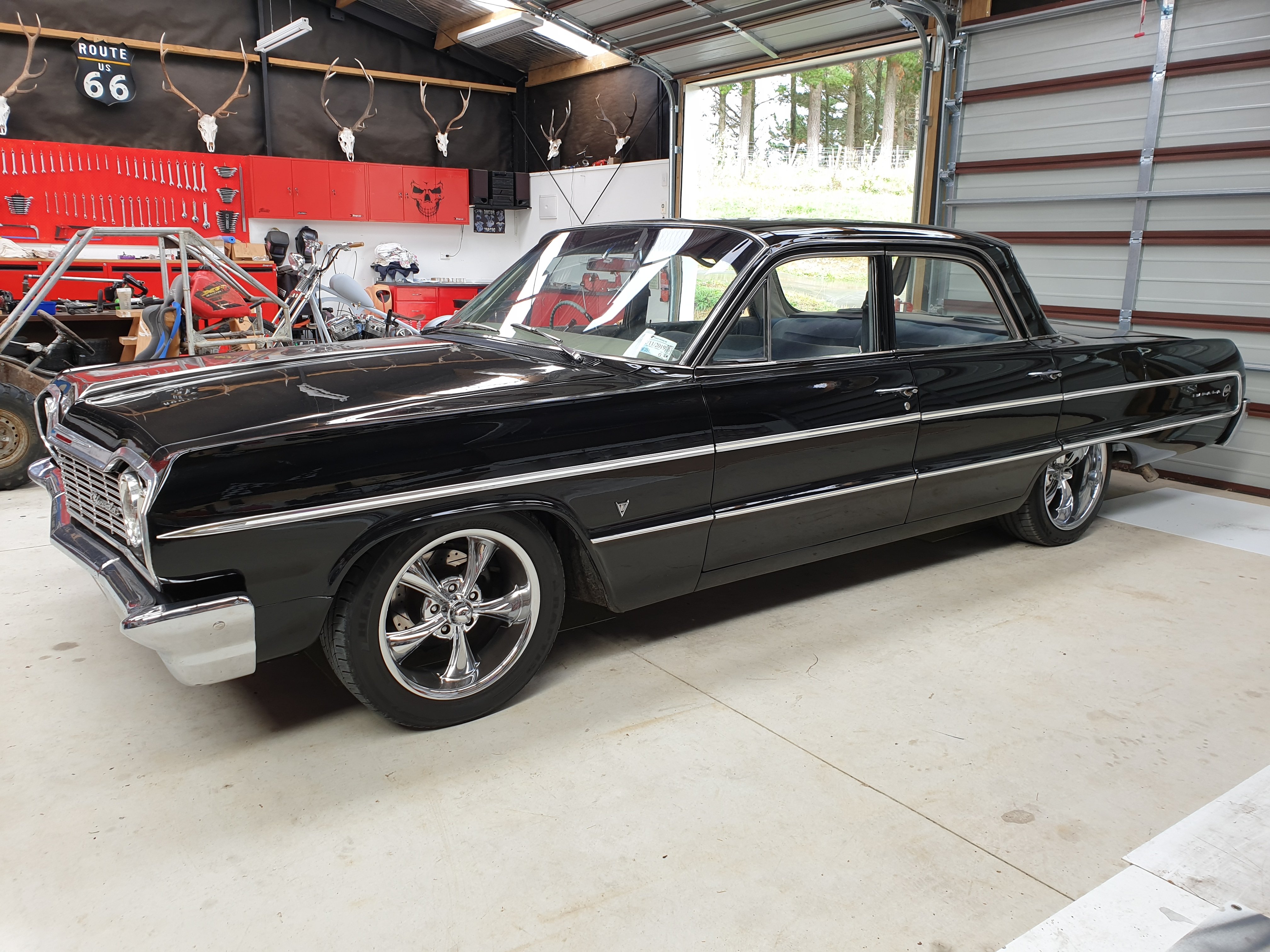
Kimjon's - 4 doors more whores (64 Impala)
Kimjon replied to Kimjon's topic in Projects and Build Ups
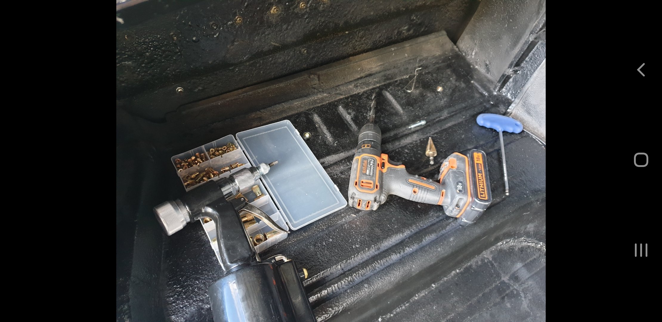
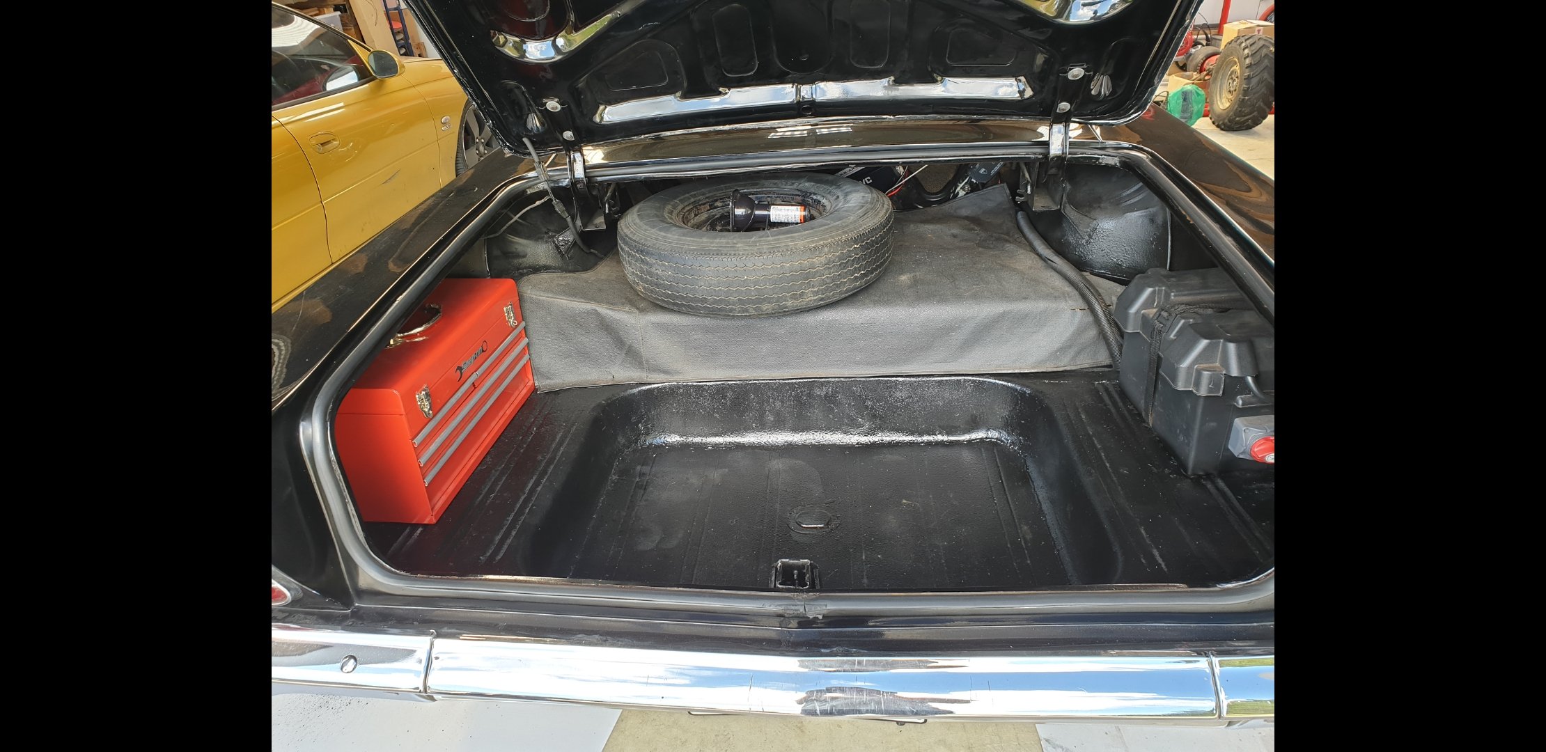
Nutserts added to floor, then I bolted a tool box into boot tucked out of the way. It also helps protect the vulnerable rear quarter panels from getting dinged by lose stuff in the boot hitting them. Believe me...I've seen a beautiful HQ monaro destroyed by a trolley jack in the boot rolling around lose, after a spirited drive from Hamilton to the Mount!
- 35 replies
-
- 11
-

-

-
Kimjon's - 4 doors more whores (64 Impala)
Kimjon replied to Kimjon's topic in Projects and Build Ups
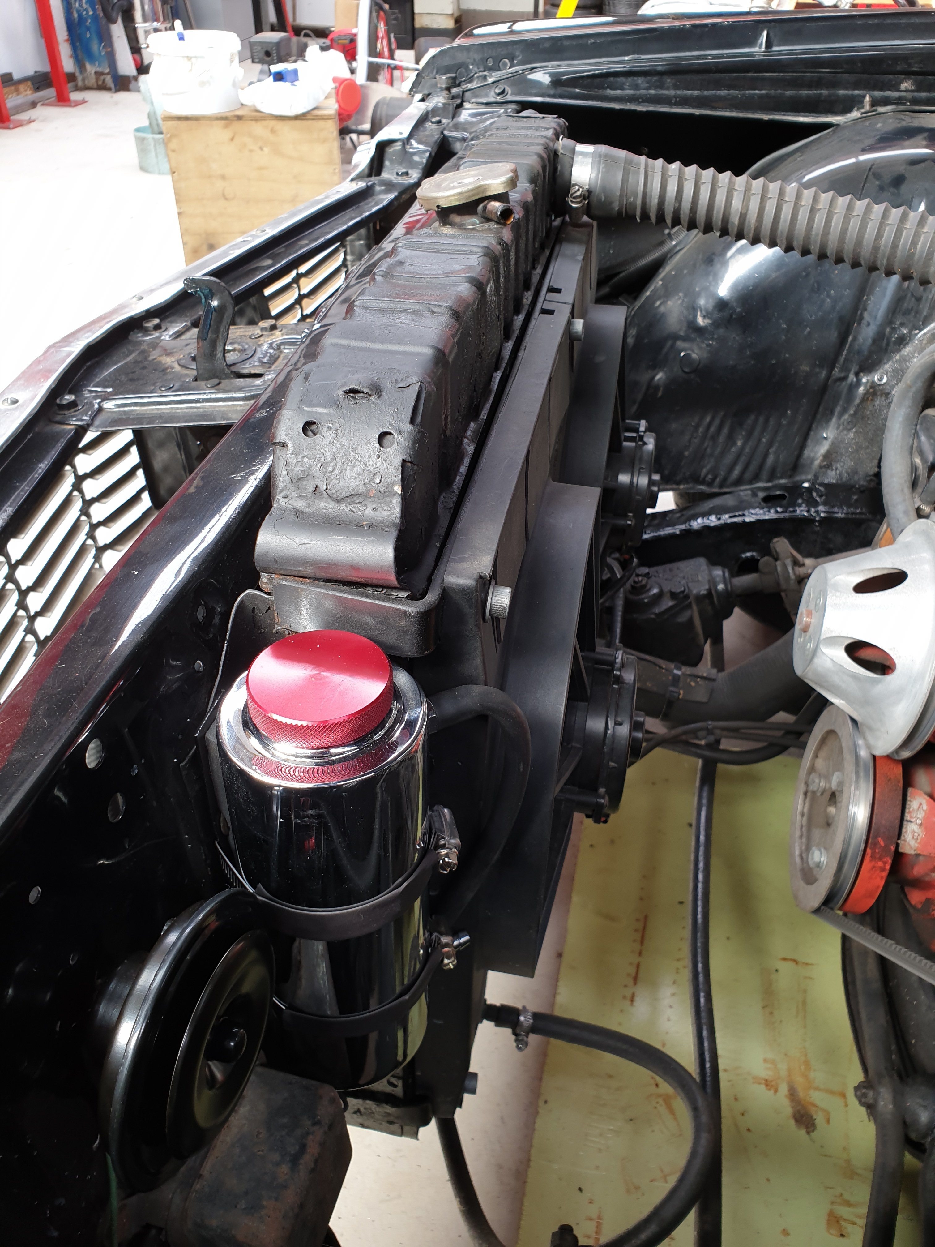
New overflow bottle, horn etc... and general tidy up of engine bay.
-
Kimjon's - 4 doors more whores (64 Impala)
Kimjon replied to Kimjon's topic in Projects and Build Ups
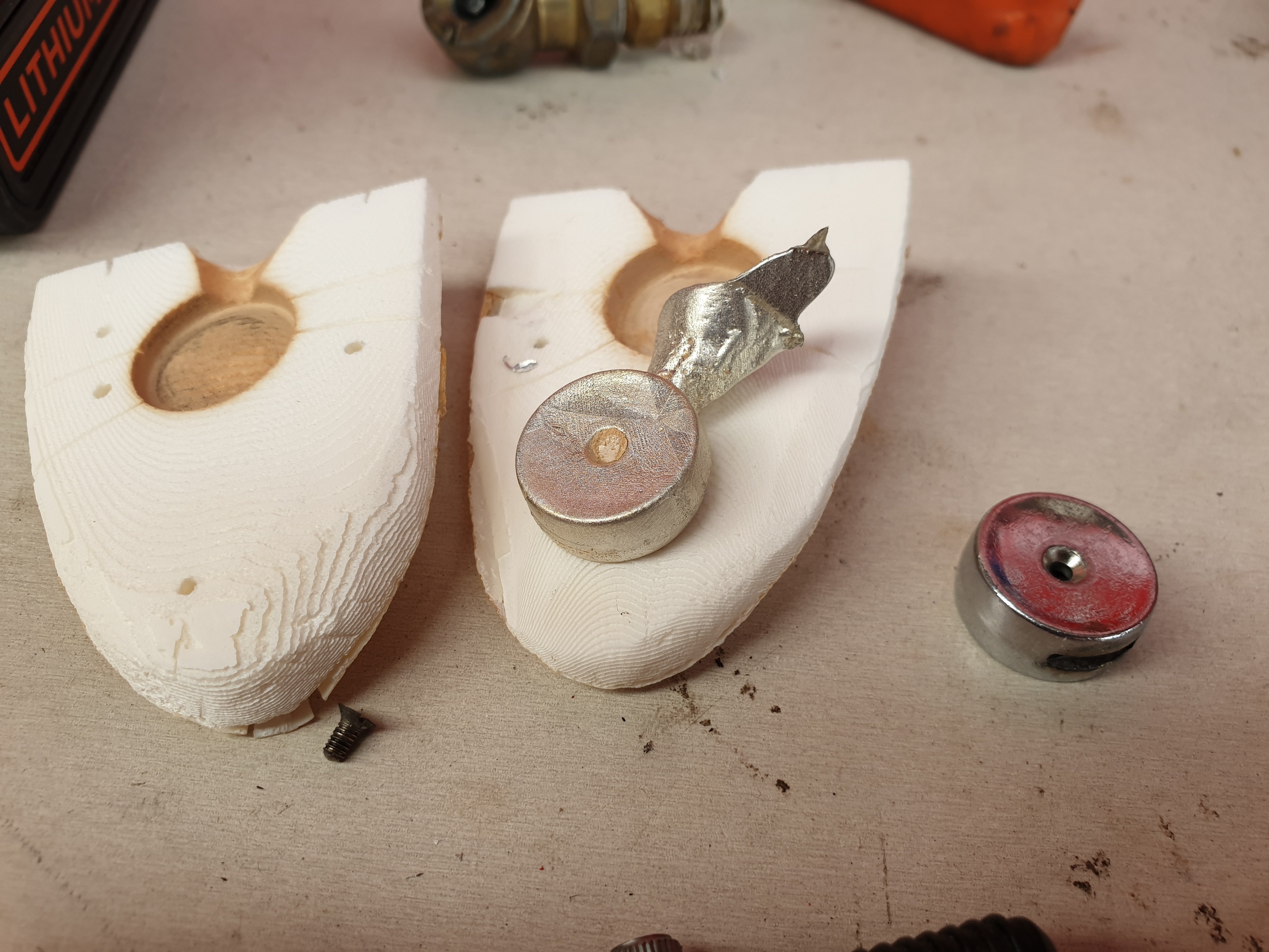
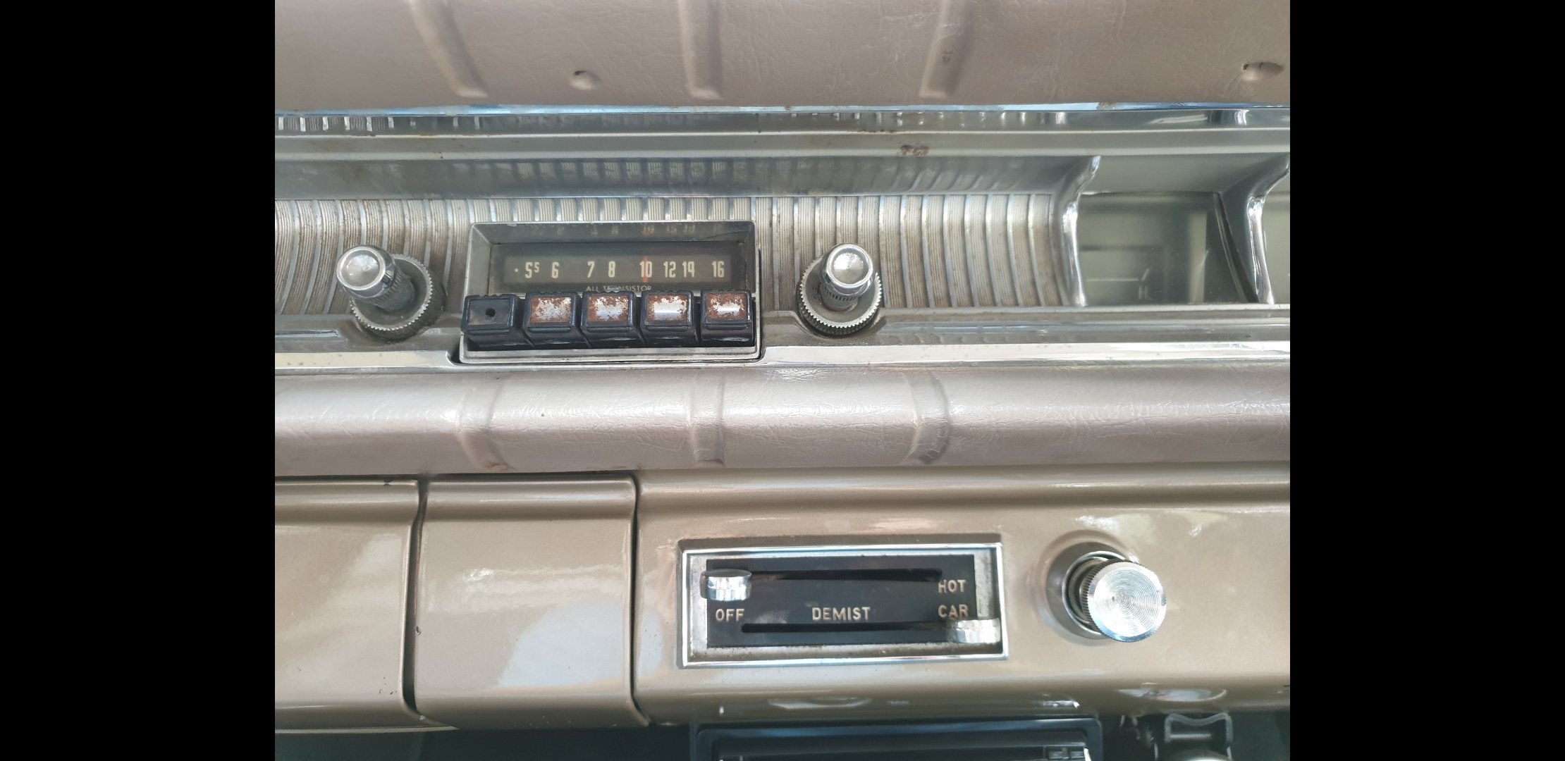
Cast some heater control knobs.
- 35 replies
-
- 10
-
-
Kimjon's - 4 doors more whores (64 Impala)
Kimjon replied to Kimjon's topic in Projects and Build Ups
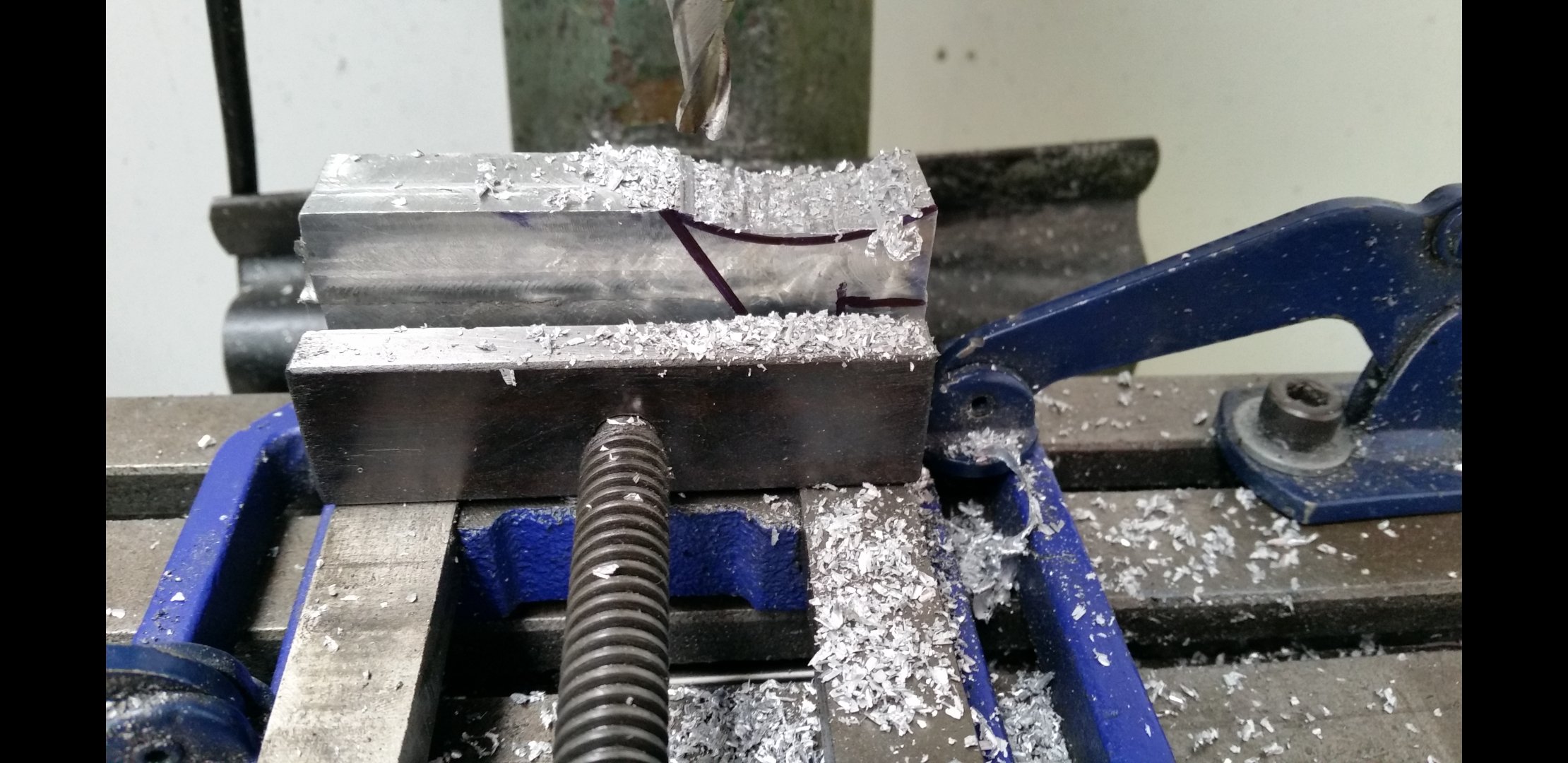
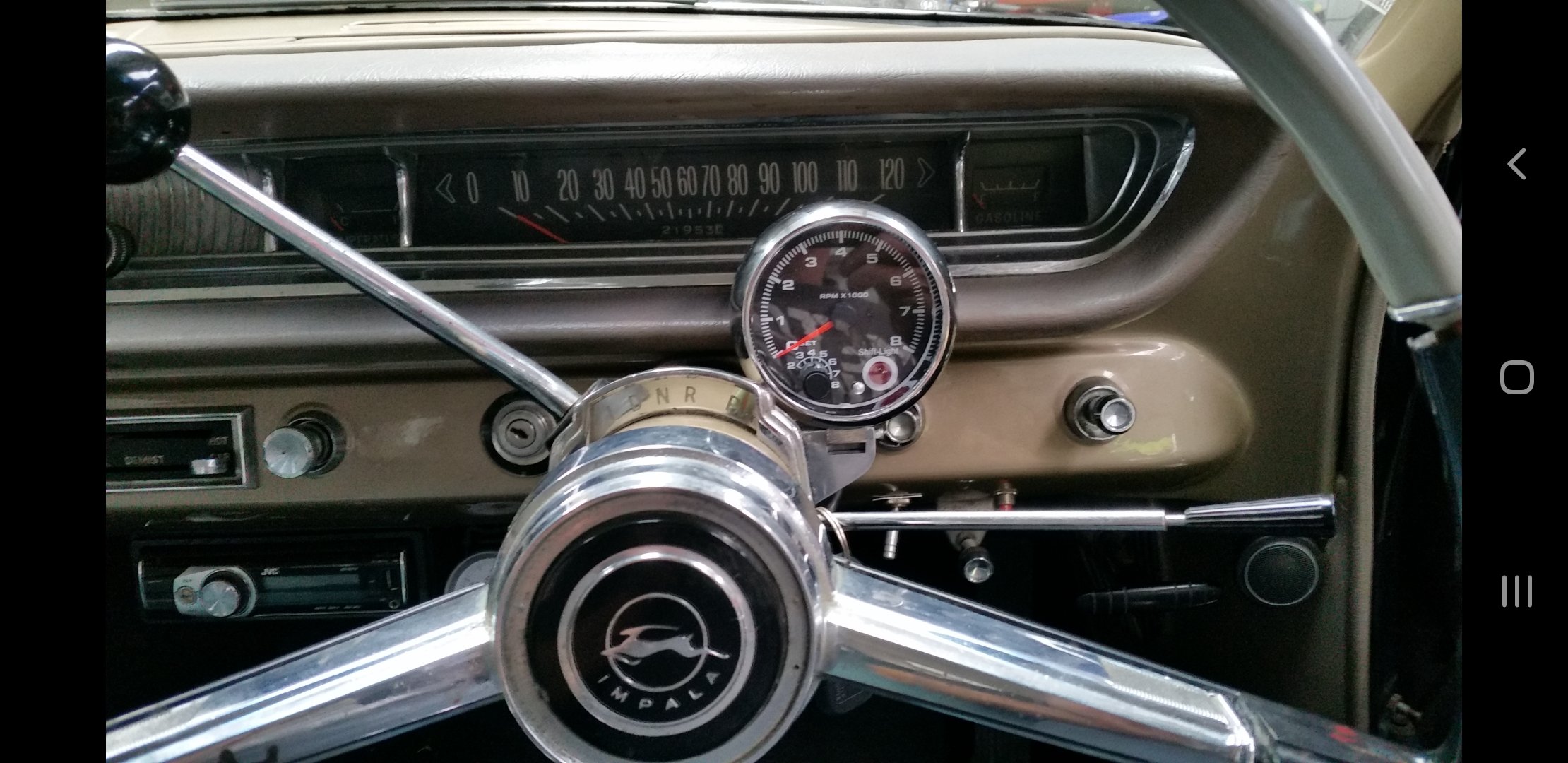
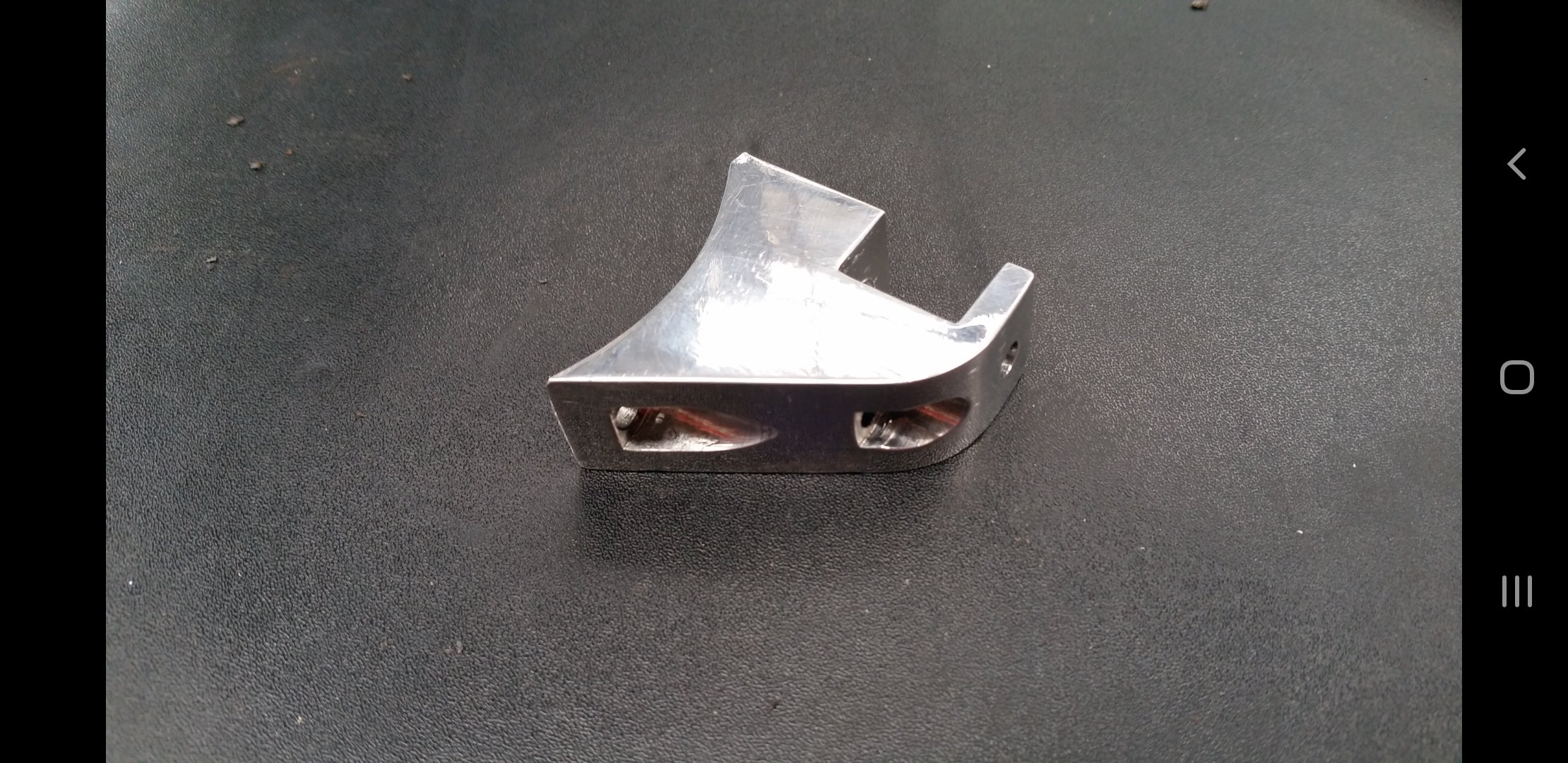
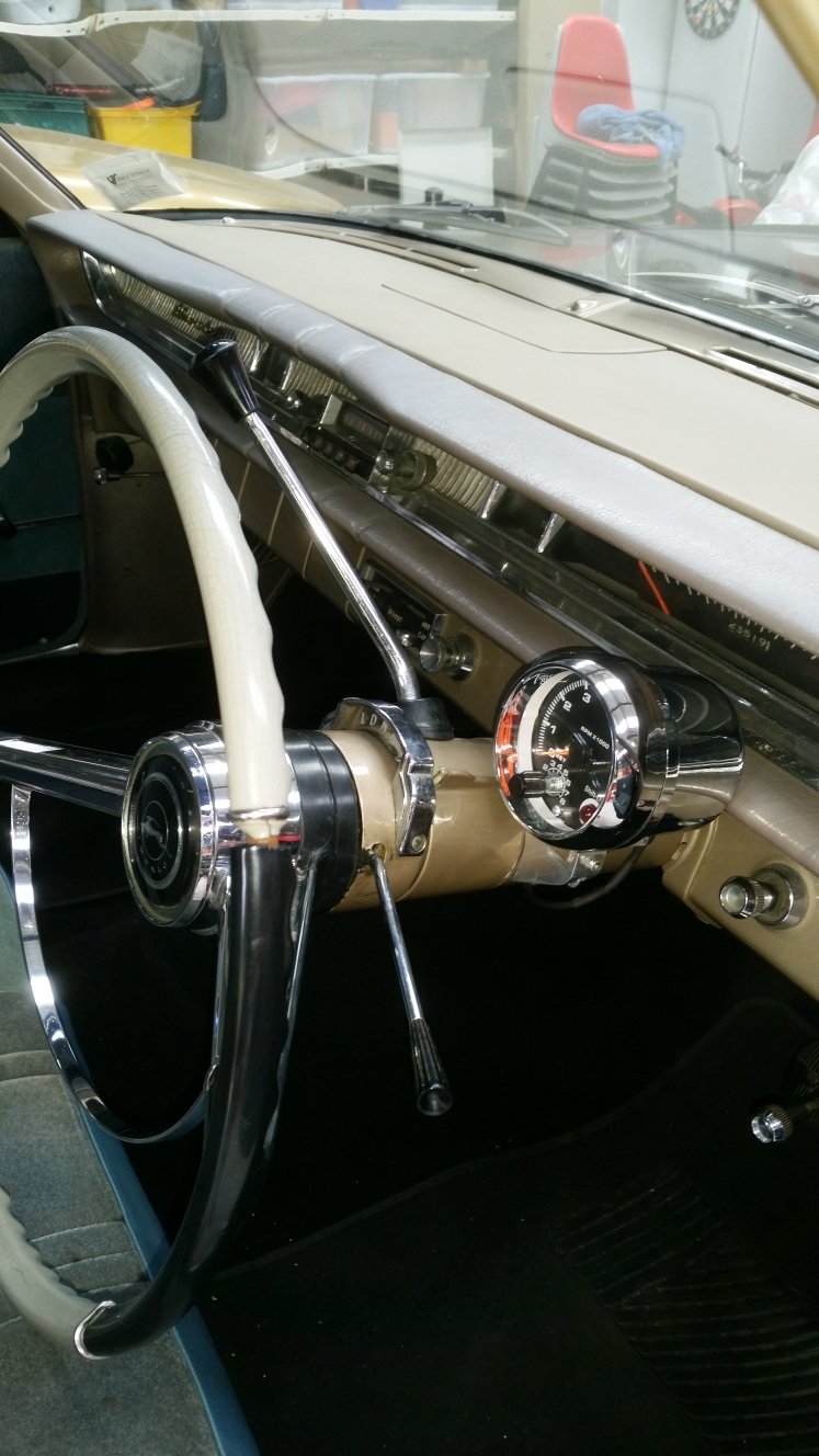
Machined up this bracket to hold a period correct looking rev counter to the steering column.
- 35 replies
-
- 11
-
-
Kimjon's - 4 doors more whores (64 Impala)
Kimjon replied to Kimjon's topic in Projects and Build Ups
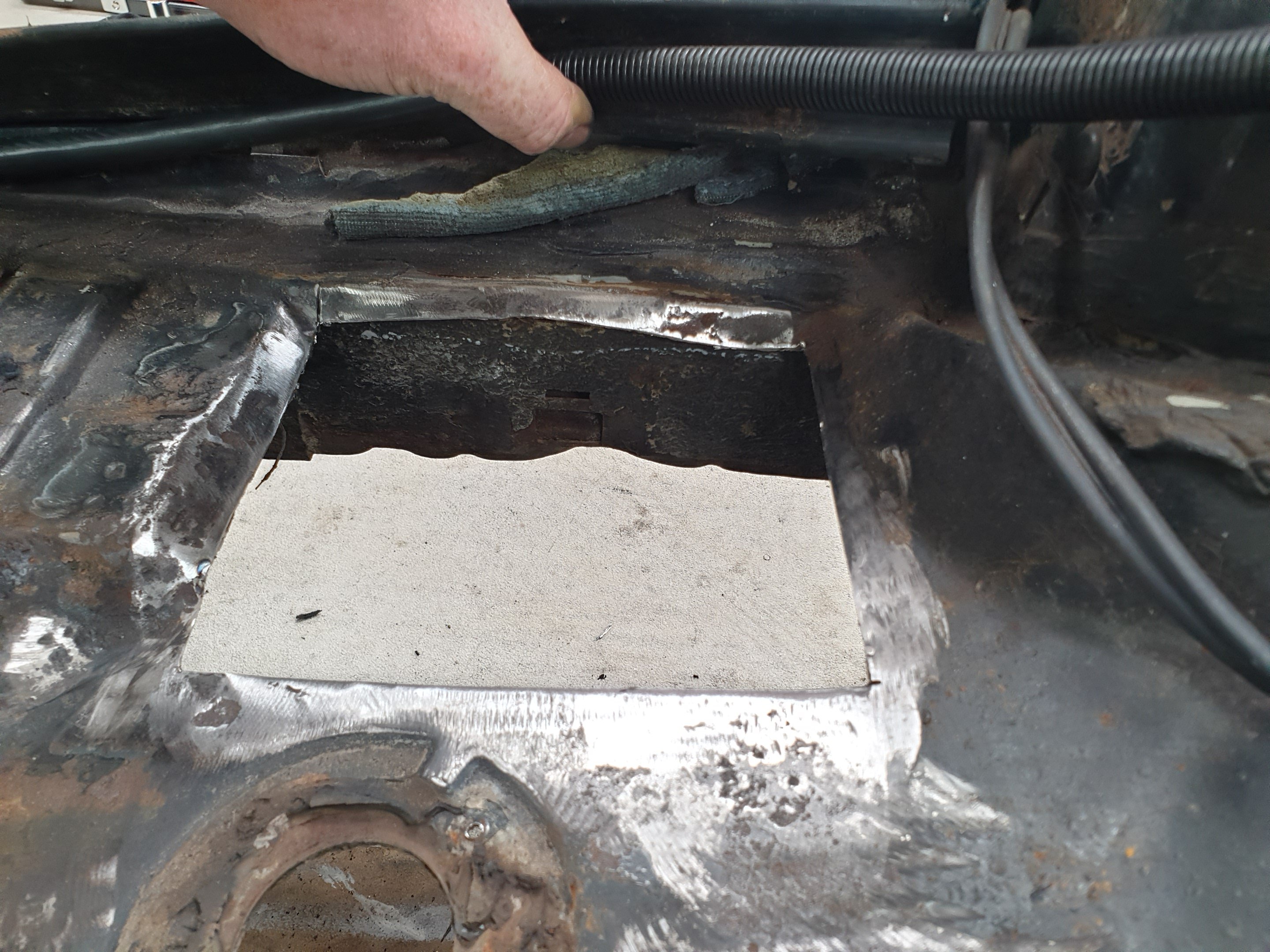
Only serious rust in this car, cut that shit out and patch her up. Luckily it's under the rear seat and won't affect the paint.
-
Kimjon's - 4 doors more whores (64 Impala)
Kimjon replied to Kimjon's topic in Projects and Build Ups
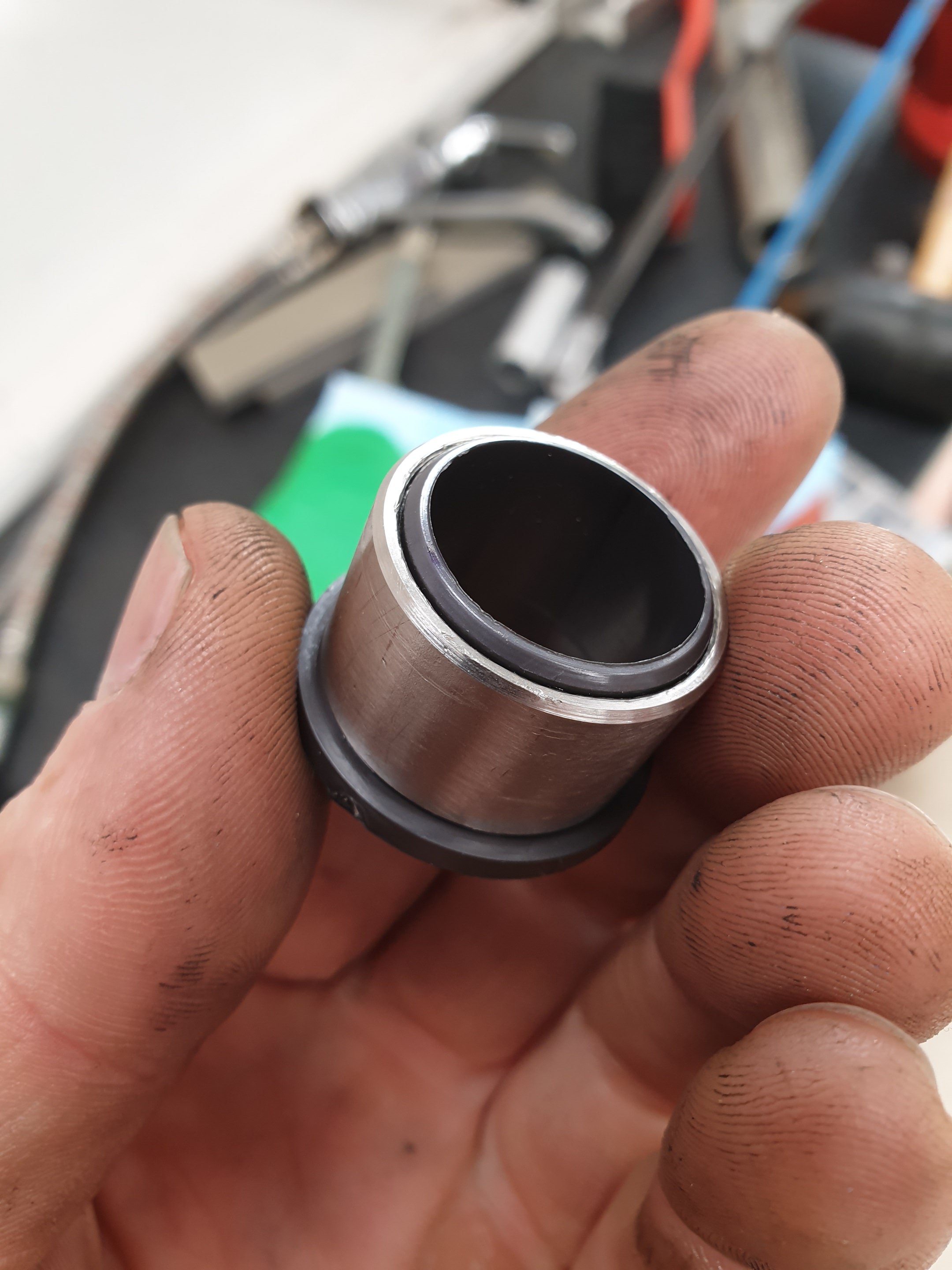
Steering column "wiggle" sorted!
-
Kimjon's - 4 doors more whores (64 Impala)
Kimjon replied to Kimjon's topic in Projects and Build Ups
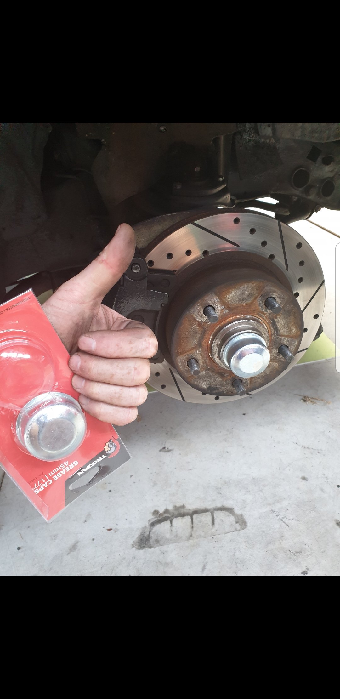
New master cylinder, flexible lines in rear, drums in rear got new slave cylinders and freshened up by machining the drums true, new pads in front, front discs machined etc etc...
-
Kimjon's - 4 doors more whores (64 Impala)
Kimjon replied to Kimjon's topic in Projects and Build Ups
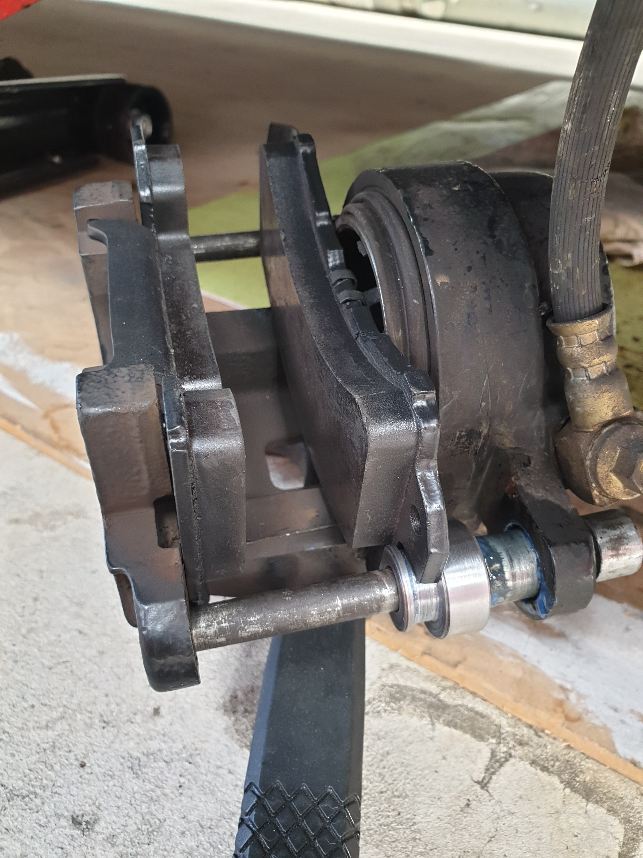
Disc brake conversion tidied up...
-
Kimjon's - 4 doors more whores (64 Impala)
Kimjon replied to Kimjon's topic in Projects and Build Ups
Getting seatbelts sorted. Came up with this solution to keep the system vertically oriented. The certifier was happy with this...so rock on!
-
Kimjon's - 4 doors more whores (64 Impala)
Kimjon replied to Kimjon's topic in Projects and Build Ups
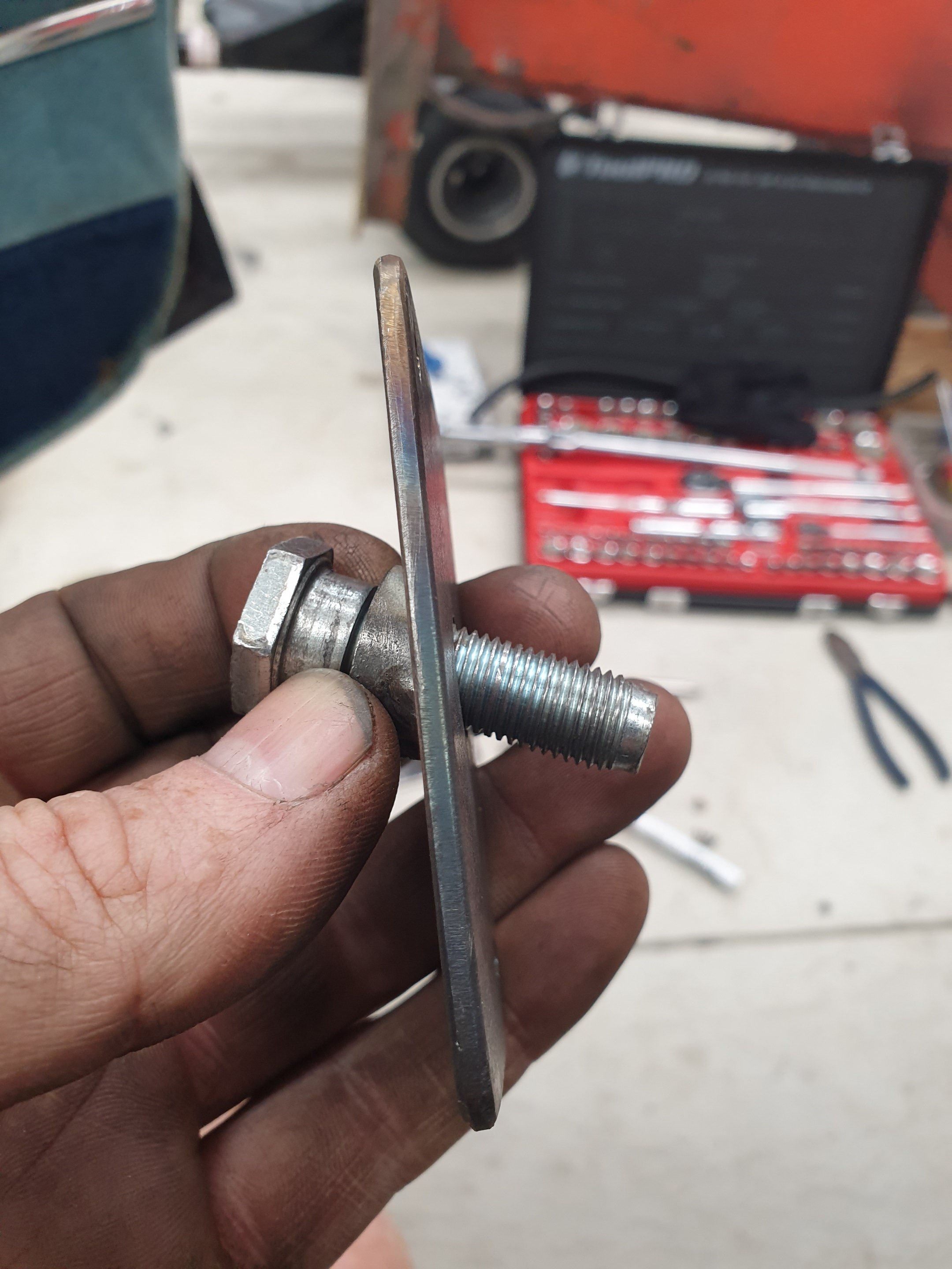
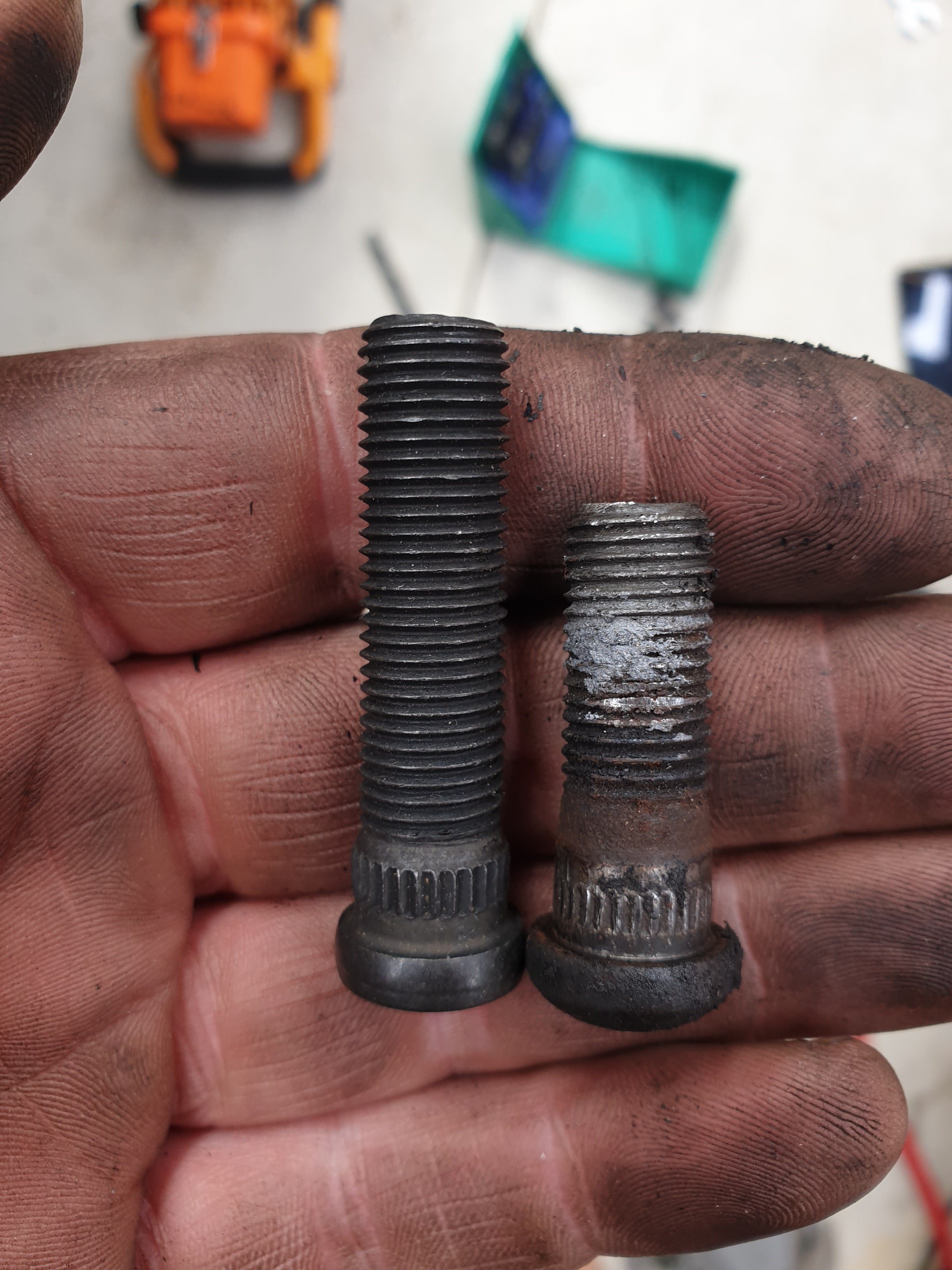
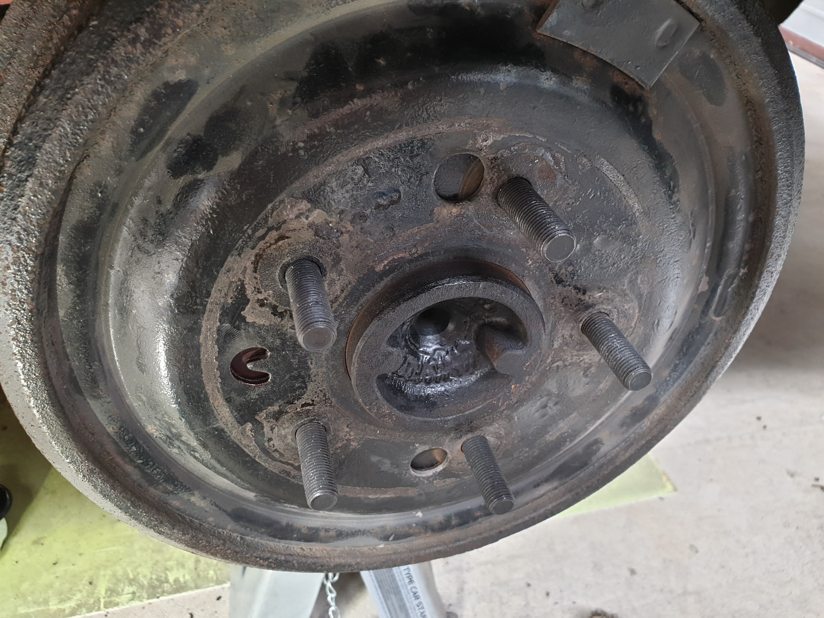
Wheel studs, needed to be longer as not enough thread engagement with mags on. Sorted!
-
Kimjon's - 4 doors more whores (64 Impala)
Kimjon replied to Kimjon's topic in Projects and Build Ups
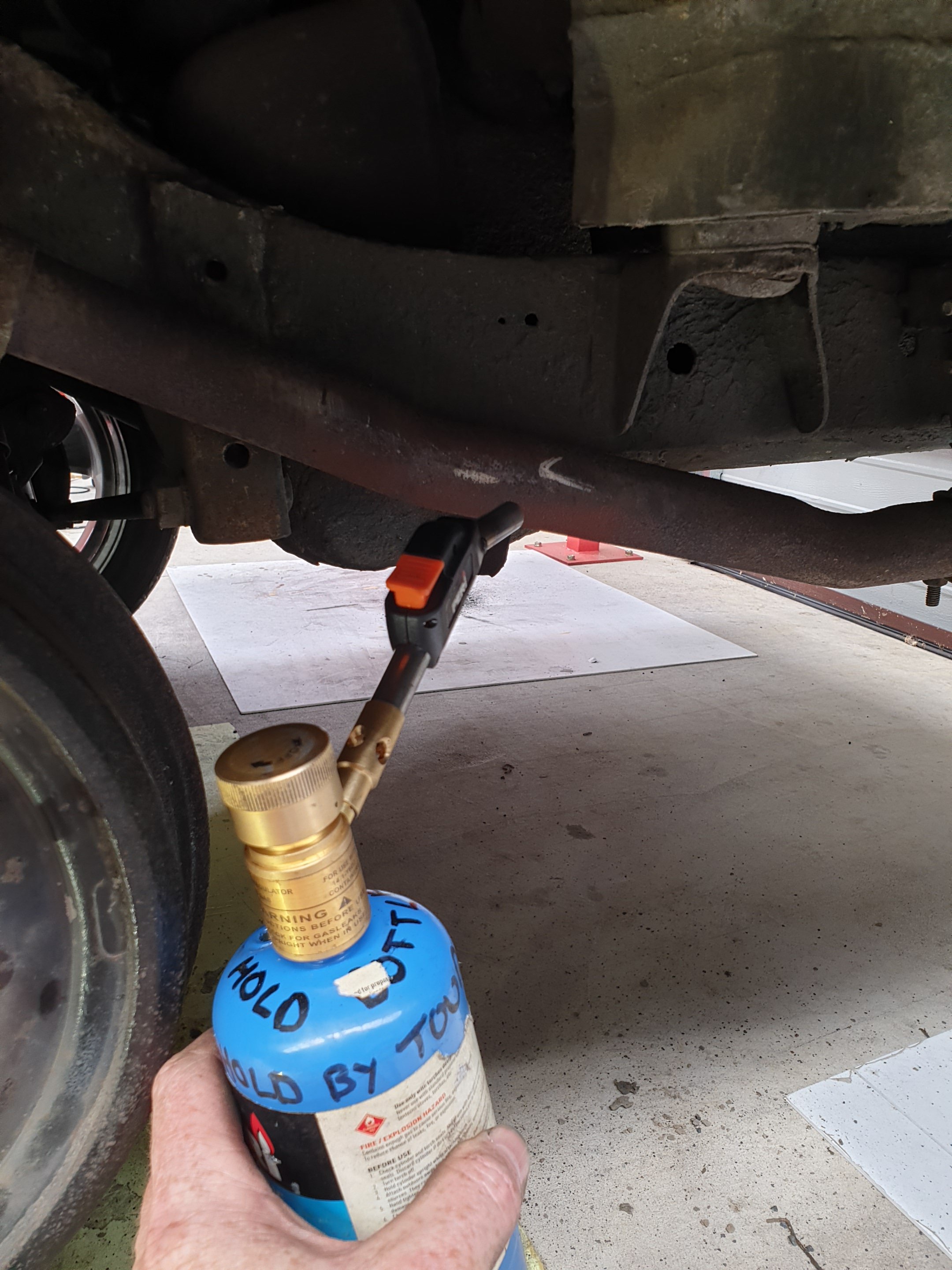
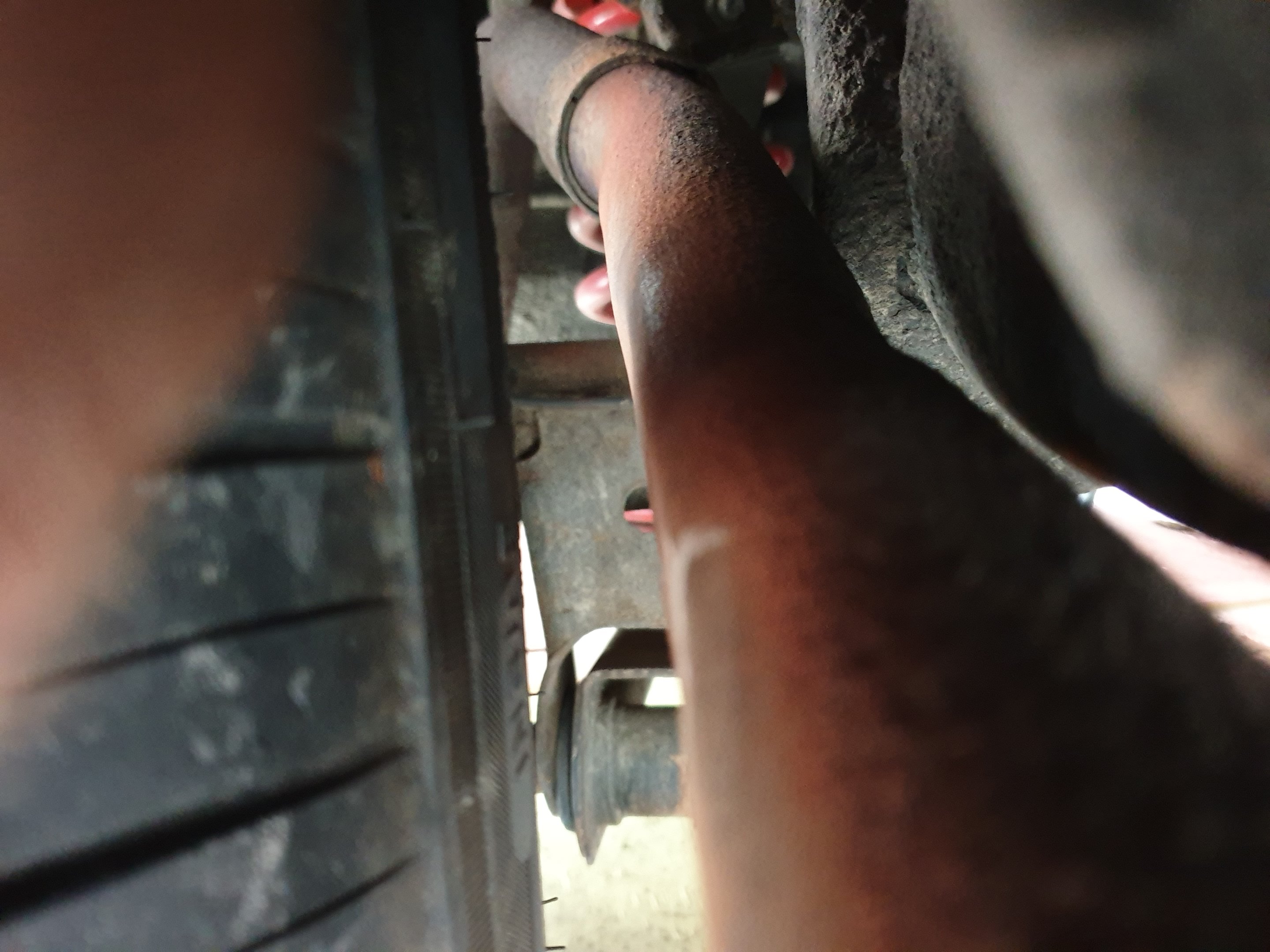
Boring shit Exhaust was rubbing on the bigger tyres. It's got a 255/45/18 in the rear...heat, hammer, and a little finesse...sorted!
-
I've been loathed to do this, but the time has come to start an impala thread. Lots a trivial shit will be posted, as the bulk of the work has already been done on this car.
- 35 replies
-
- 15
-
-
Okay - rears are sorted. Still after the front ones...soooo...anyone got a go to place? I've never thought of it before, but every old car with aluminum mags will likely need this done. Steel rims are only about 5mm thick, whereas aluminum wheels are more likely to be 20mm or thereabouts...so makes sense in hindsight. However I suspect, like me, most are oblivious to this.
-
I've been Google searching for about 2hrs now...well off and on. Finally found a lead on something I could use at a reasonable price. https://www.allports.nz/category/346-wheel-studs-nuts 20x$5 is fuckloads better than 20x $18!!! I'll chase this up tomorrow. As for the spigots- think I'll just make them. My sizes seem huge compared to what available on trademe etc...
-
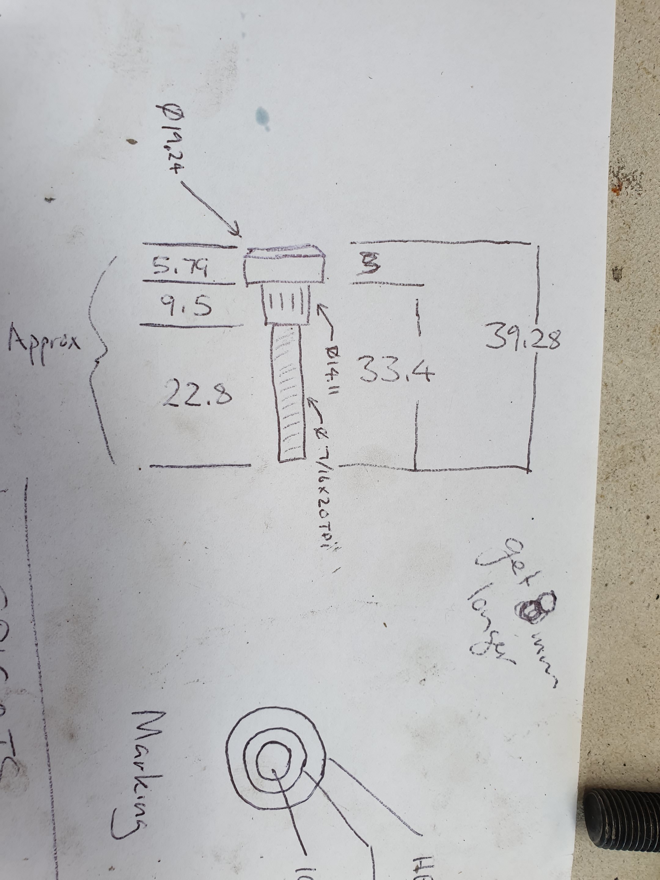
This is what I've got in the front, I'm after 10 of these...but about 5-10mm longer. The rear is similar, but the spline section is much smaller. Haven't got measurements on hand. Thread is 7/16x20 on all of them. Also after 4x concentric hubs to locate my wheels on the hubs. Wheres a good place to find this stuff??? Google searching is drawing blanks in nz.
-
Random slightly cool stuff you built but not worth its own thread, thread
Kimjon replied to h4nd's topic in Other Projects
I think the issue came about because I had a couple bits of rubber hose filling the gap on the pin/pad to centralize the pads. This was to stop them rattling when not braking. I'd had it like this for a longtime with no bad experiences... however this drew attention to this part, and he wanted a better solution. He wasn't happy for me to just take it out and restore the factory rattle, as it's a shit design to begin with. The way I look at it, any problems that can be solved with a bit of time or money is a real problem. So just get on with it... -
Random slightly cool stuff you built but not worth its own thread, thread
Kimjon replied to h4nd's topic in Other Projects
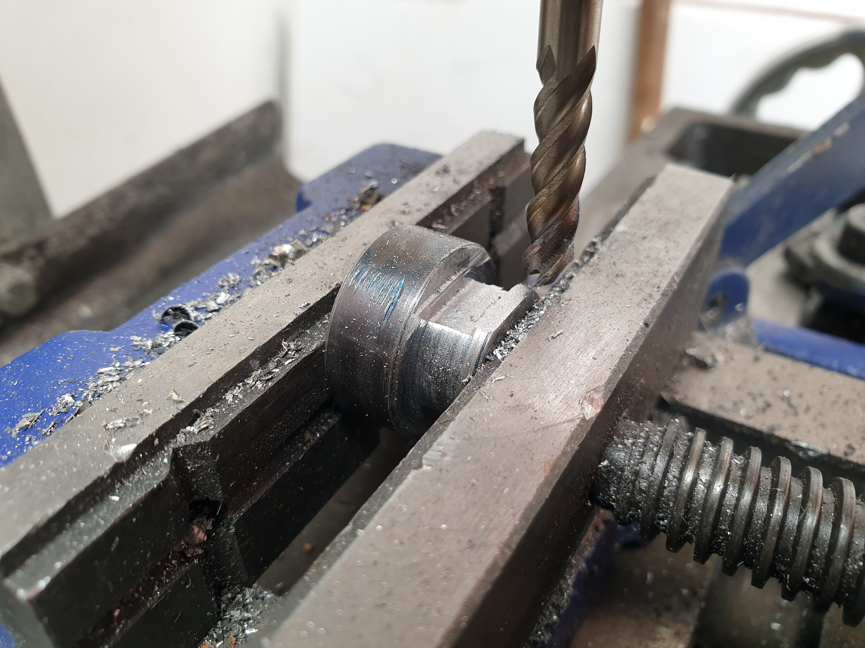
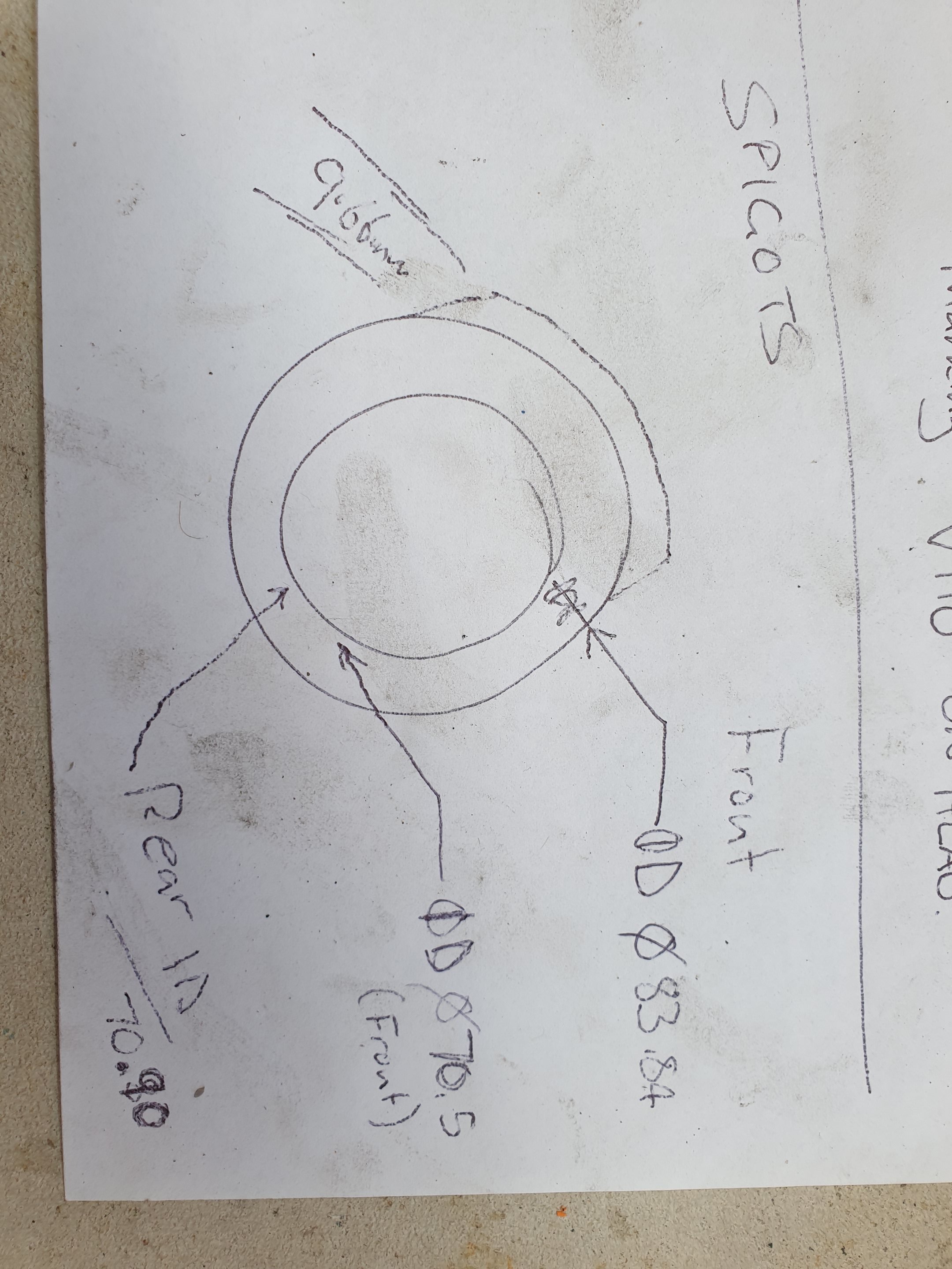
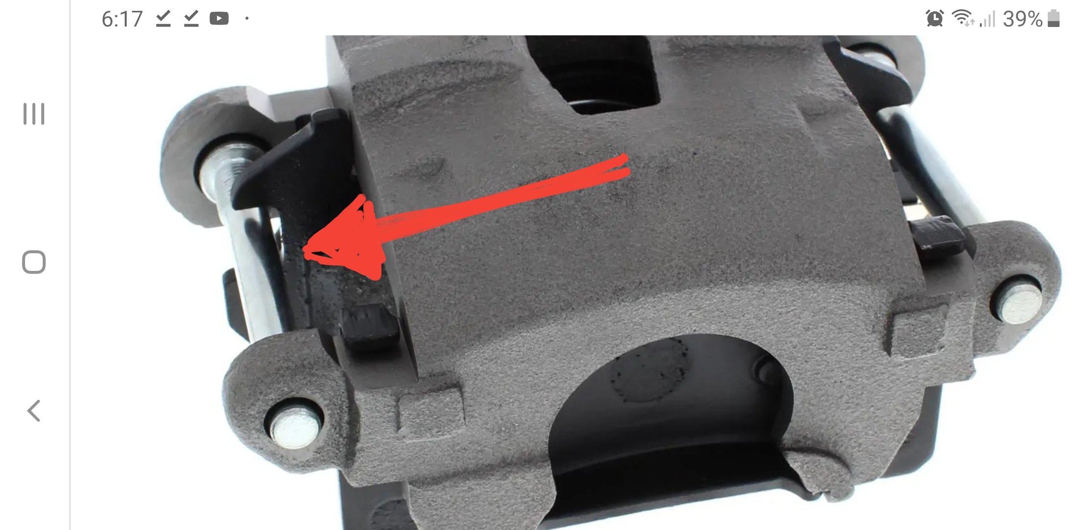
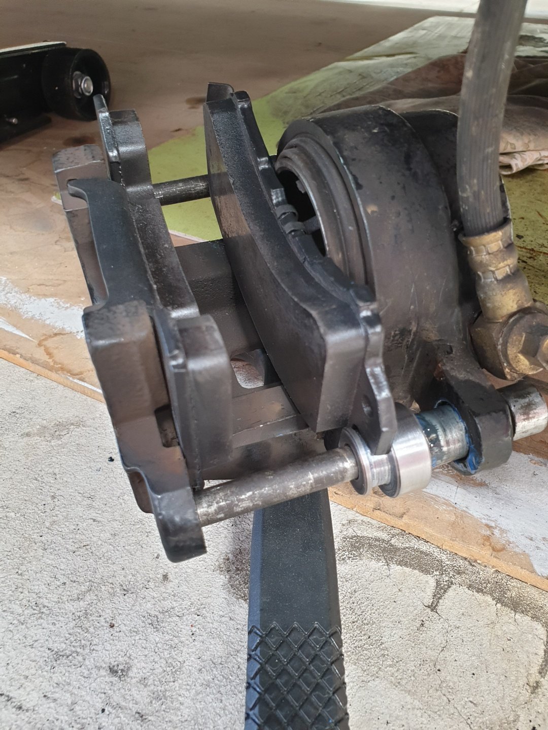
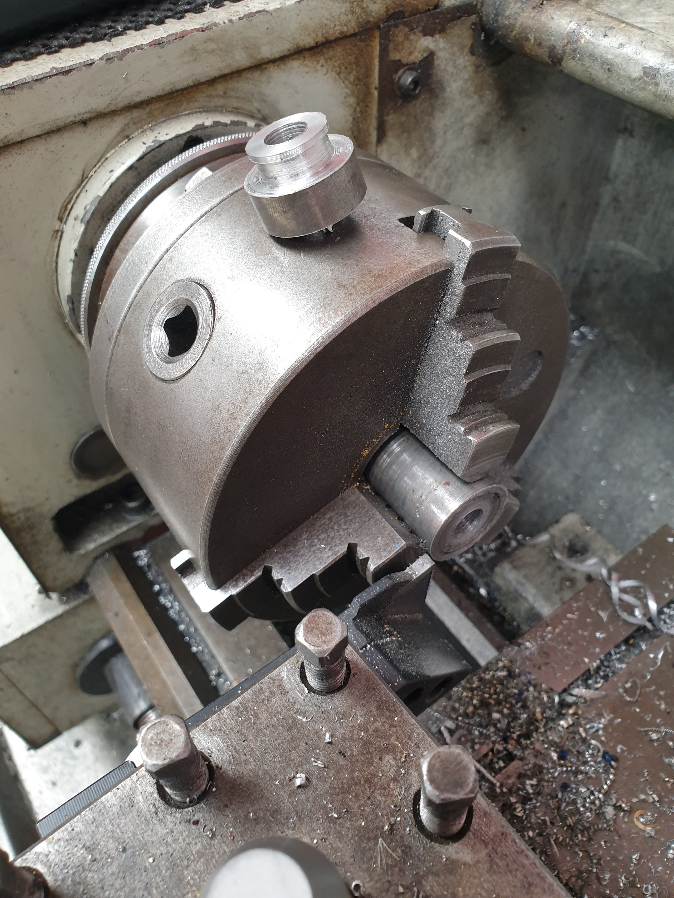
Today's efforts. The certifier wants the brake pads contained tighter within the front calipers. They are GM metric calipers like on most chevys from about the 70's to 90's. From the factory they come like this, with a huge gap of about 17mm in the pads, and a 10mm pin going through it...so about 7mm of slop. The certifier wasn't happy with this, even though it's a factory part. But he suggested I make something up to take out the slop, but not hinder the functionality of the brakes or make contact with the rotor. If I was able to achieve this - then the brakes would pass. So time to make shit happen: 4x turned inserts. Milled slots to fit pad steel. Test fitting, yip...success! Took 4hrs....with lots off going back and forth between my lathe, mill and car. Mainly due to stamped steel the pads are made of was all different sizes, so all 4 spacer are custom fit to each pad location point. Cunt of a job getting it all figured out...but one less thing to do.
- 1289 replies
-
- 12
-
-
Maybe. It's a good idea, thanks.
-
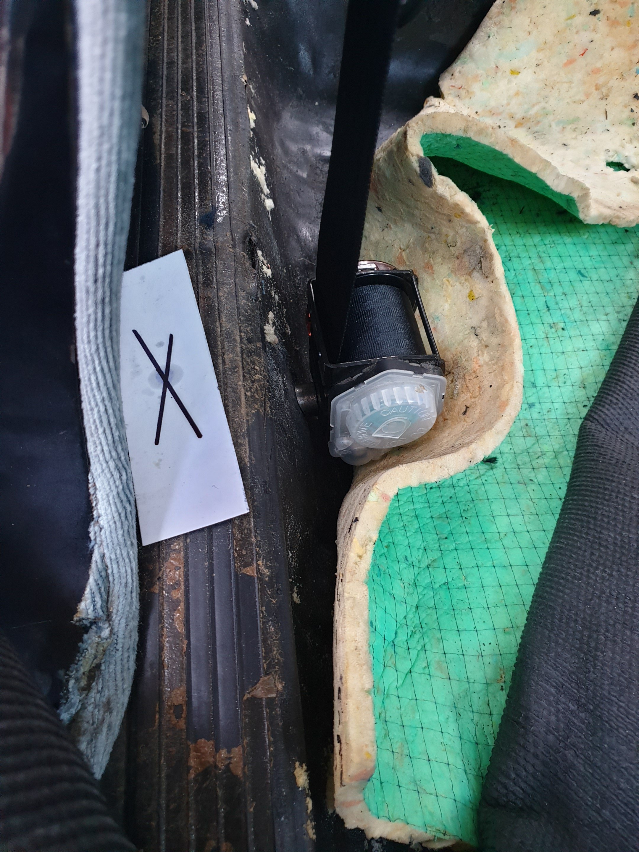
I think the sill would prevent this option from being viable. I'll check it out tomorrow...after 15hrs working non stop on my car I'm a bit over it tonight. Where that paper with the x on it is the sill, so I cant drill in there as I wouldn't be able to access the other side. If I go any further inwards on the floor to find the flat area I'll likely be too far inwards and foul on the seat. But I'll check for sure tomorrow. Thanks for the reply, much appreciated tho.
-
Random slightly cool stuff you built but not worth its own thread, thread
Kimjon replied to h4nd's topic in Other Projects
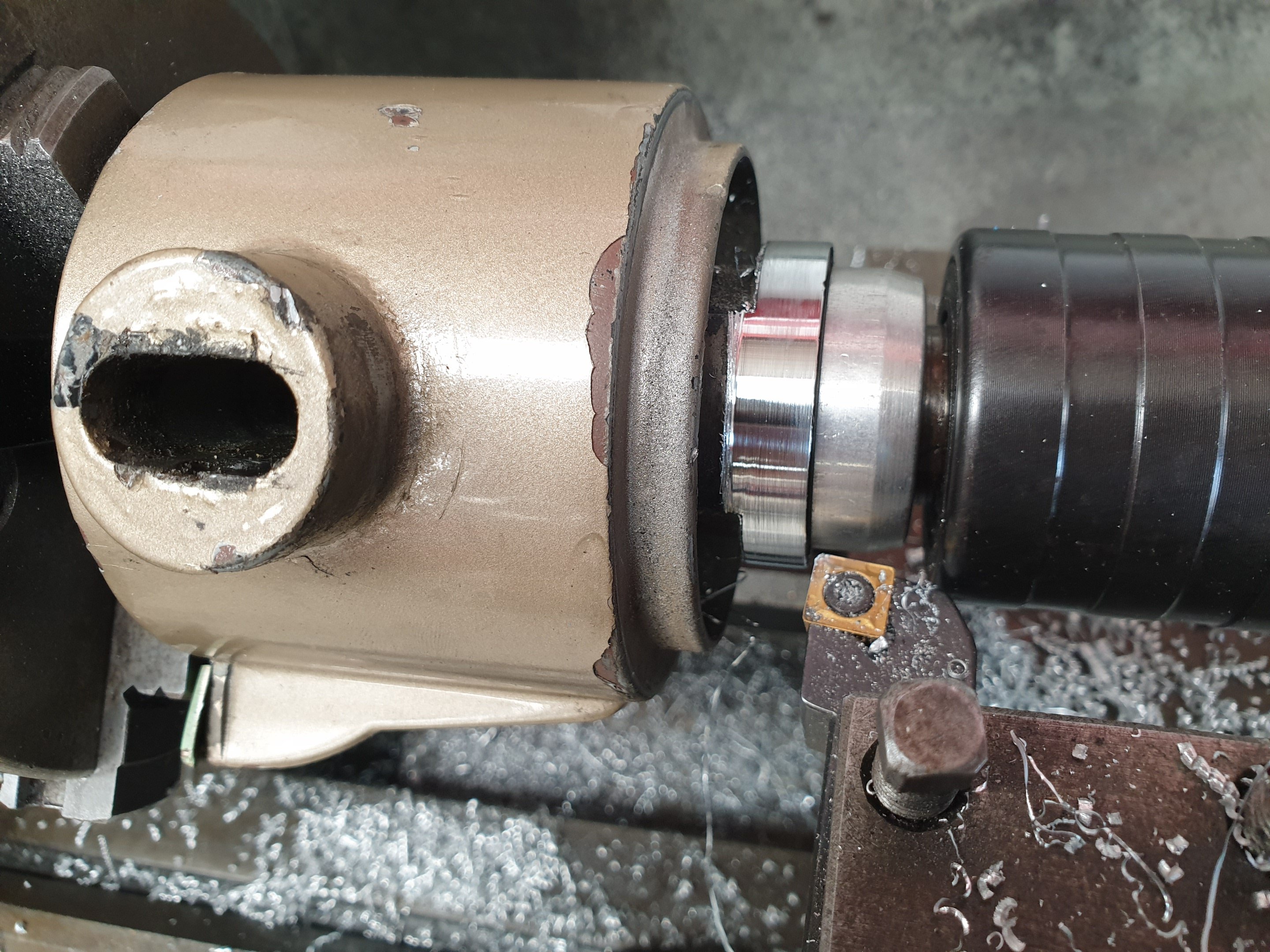
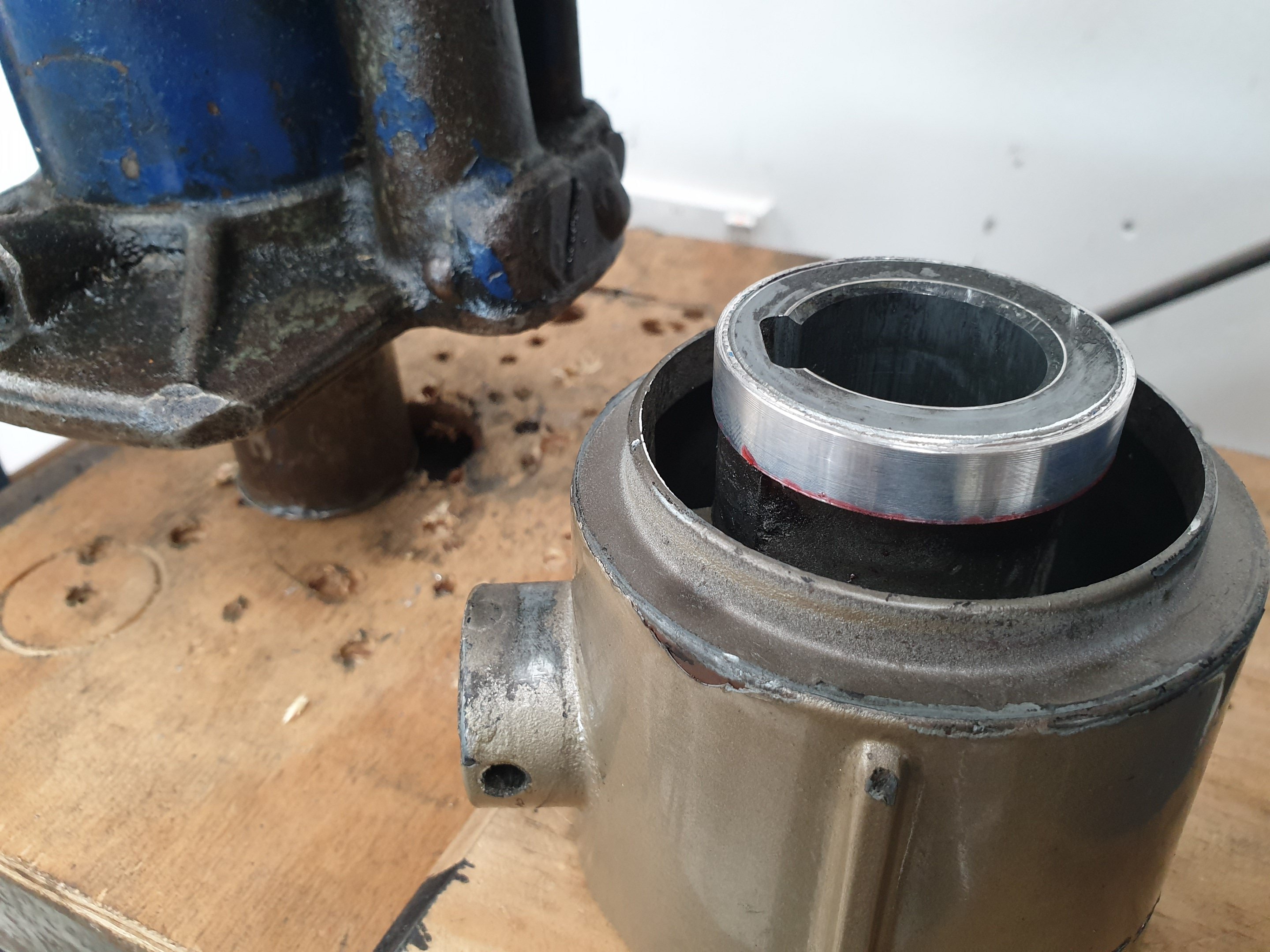
Had excessive play in my steering column. Stripped it down and there really wasn't anything worn or actually wrong as such. Some parts still had paint under the grease...so it wasn't flogged out. I think the factory clearances are just very sloppy and because it's a shaft, within a tube, within another housing - that equals compounding errors x3 that all add up to felt play at the steering wheel. I pondered this for a while, wondering how I was going to keep my certifier happy and tick this box? Then came up with a solution. I turned up this bushing on the lathe from stainless and then press fit (plus epoxied) a nylon insert. The actual steering shaft within the gear selector tube can now run on this to remove any minor bearing movement there was before. The ractory fit bearing is still in there too, should this ever wear out...though my 20 year old ride on mower uses these bushes on the steering shaft and no supporting bearings at all and it hasn't worn out yet. Then I made a jig up to hold the gear selector boss in the lathe. I took a few cuts off the tip only (the keyed shaft inside runs full length) and then turned up a shim to add more material back on than what I started with. I press fitted these parts together using loctite just to make sure it stays together. This shim ring perfectly centres the gear selector inside the main steering column housing. A liberal coating of grease and I put it all back together. This part only moves about 60° from Park to 1st on the colum change, so it's not going to wear out this century. Its rock solid now, zero unwated movement, better than the factory ever made it...
- 1289 replies
-
- 19
-
-
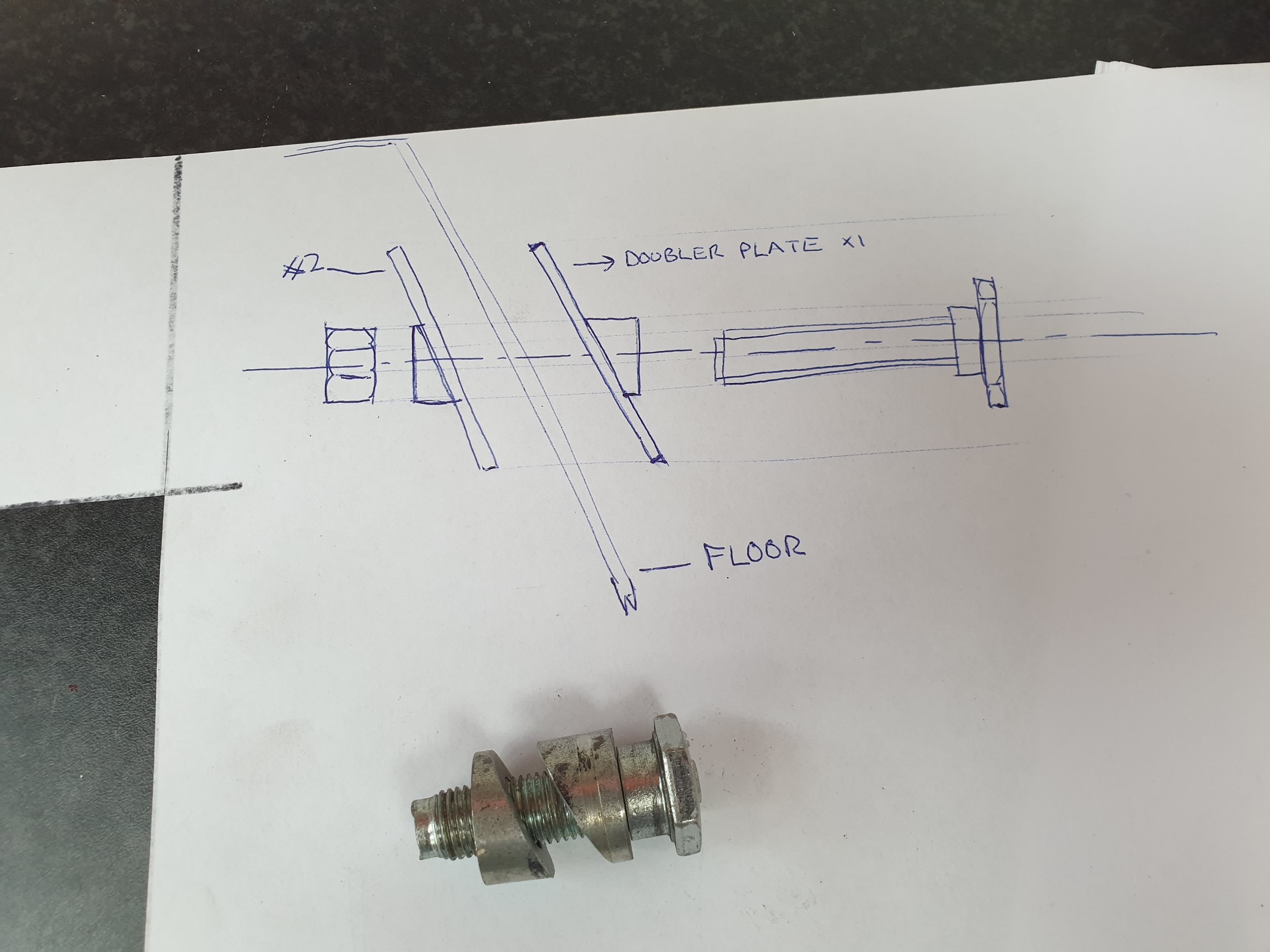
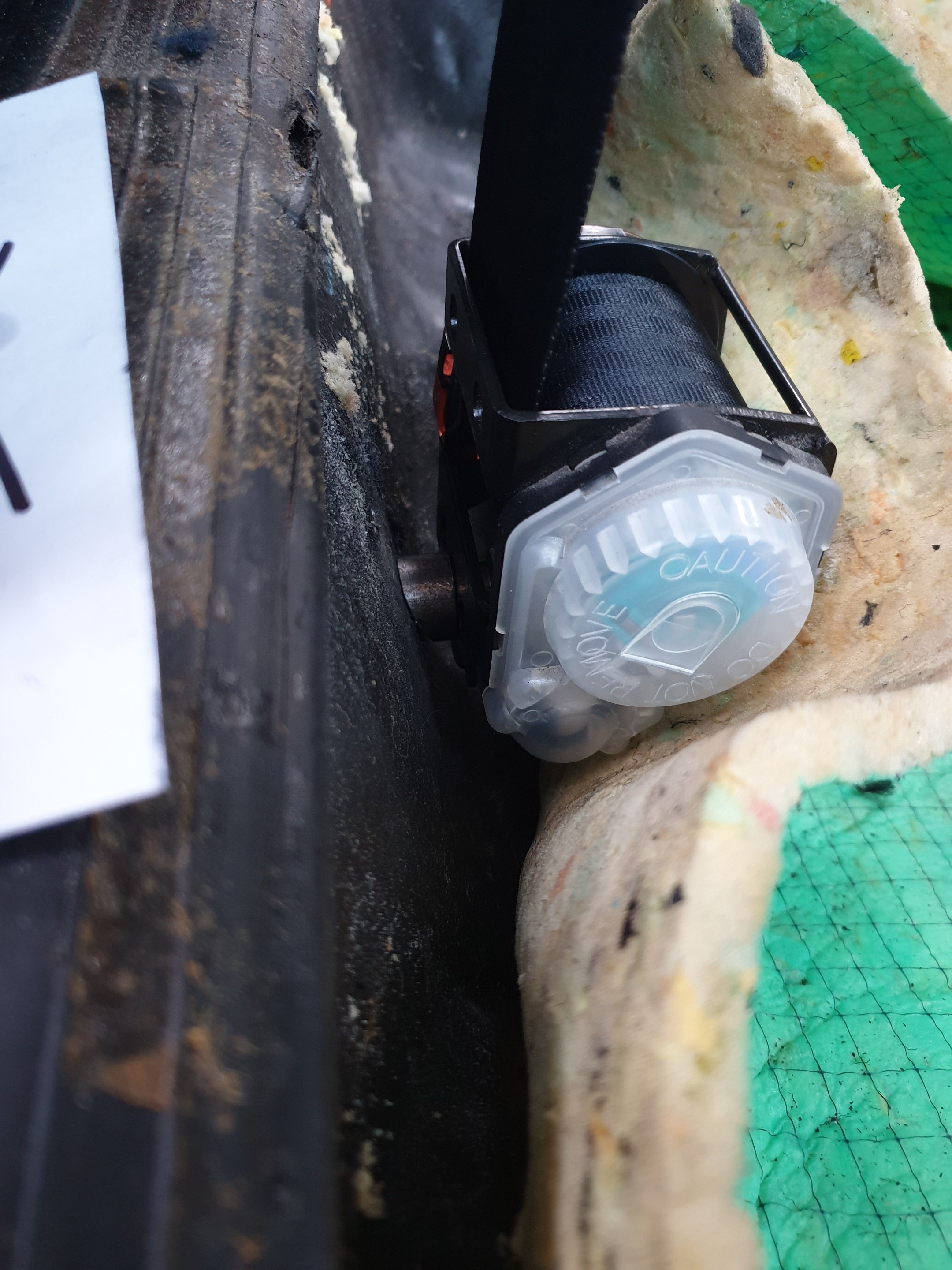
Balls! I tried mounting the retractors on the factory holes...looks good, clearances are good, it's in the magic H zone...but they don't work on that angle. Mine are designed to be mounted straight up/down. So I think I'll need to do the double plate method after all. Edit: Is this a viable alternative? And imagine there's a double plate, mounted it would look like this - held vertical against a non vertical surface
-
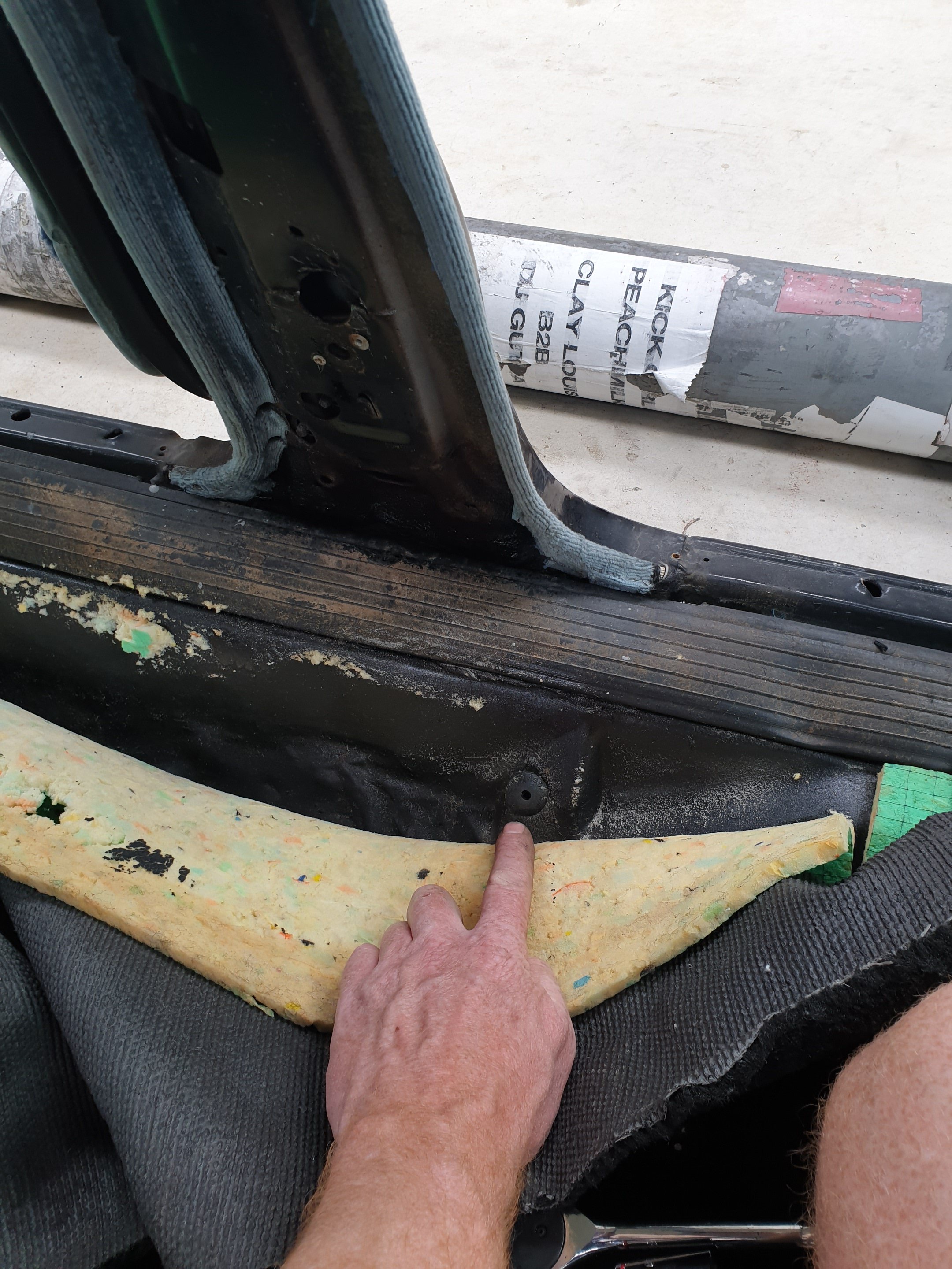
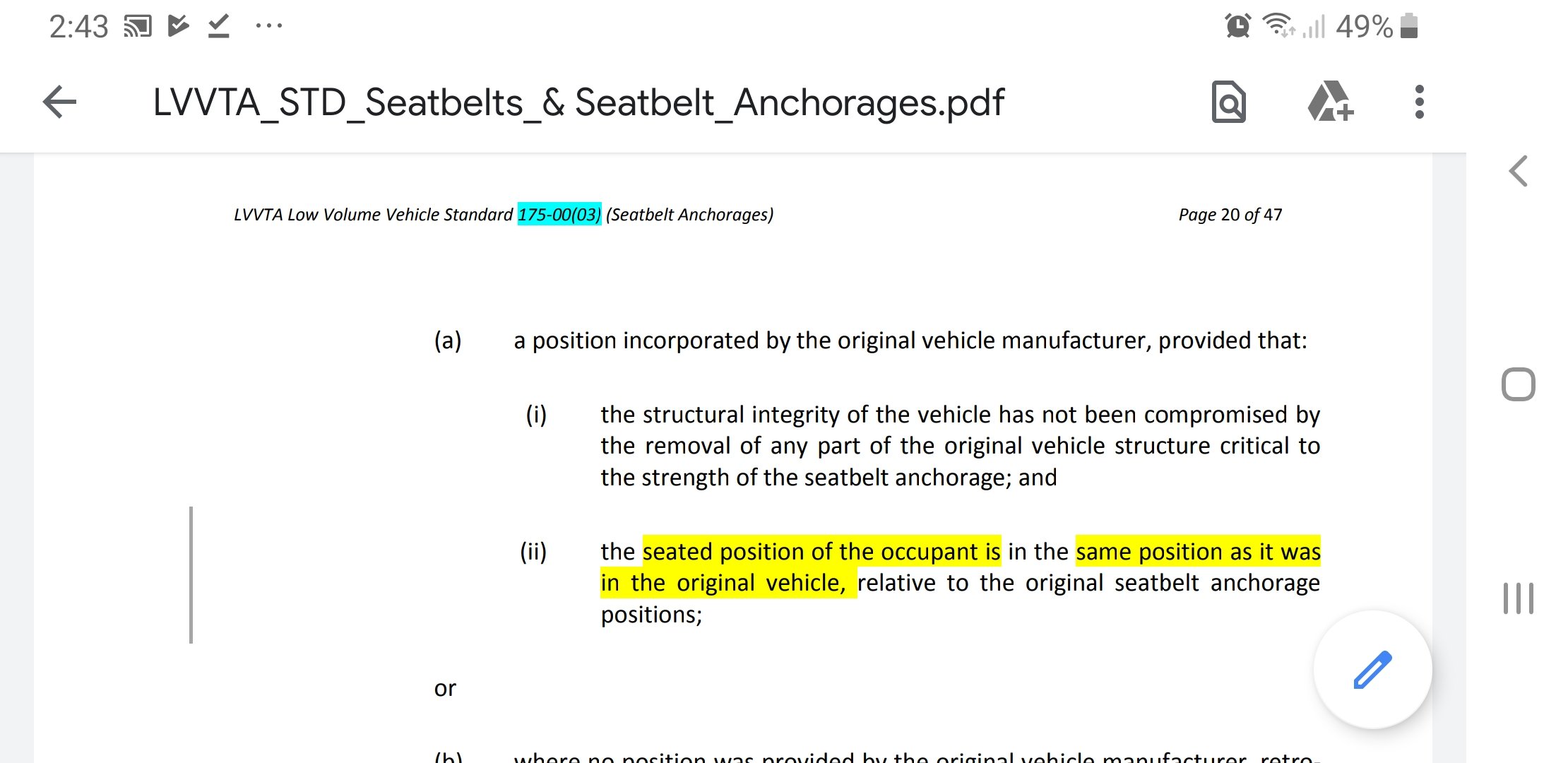
With the seat belt anchors, I removed the seats carpet etc...and under all that are factory original mounting points on the floor. These go through an overlapping seam on a crossmember flange. Can I just use these? Or do I still need to put in double plates? This rubber bung was in the threaded hole. Its behind the seat mounts, but at the very front of the B pillar. This section says it's okay...but man is this shit confusing for me. 50 pages on how to mount seatbelts! Surely 2 pages with drawings would explain it far better than 50 pages of words ever would?
-
Less work and not ruining my paint sounds good. He was happy with the upper mount point, but not the lower anchors. I'm capable of doing the work, just wanted to make sure I was doing it correctly first. Cheers
-
Front seat belt lower anchor points on or near a B piller. Can someone post a photo of what an acceptable one would look like installed on an old car...bonus points if it's an impala? Or perhaps a link to where I'd find the required standards? I need to sort this issue out for a cert, and I still haven't got my head around it yet.