Flash
-
Posts
1,718 -
Joined
-
Last visited
-
Days Won
2
Everything posted by Flash
-
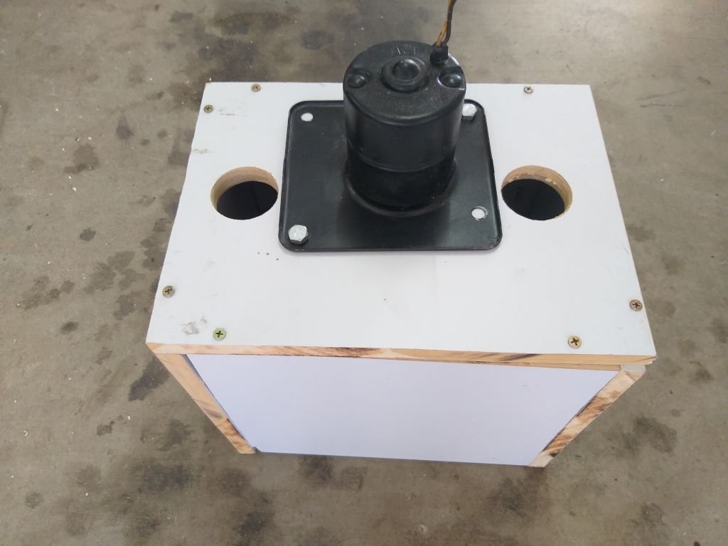
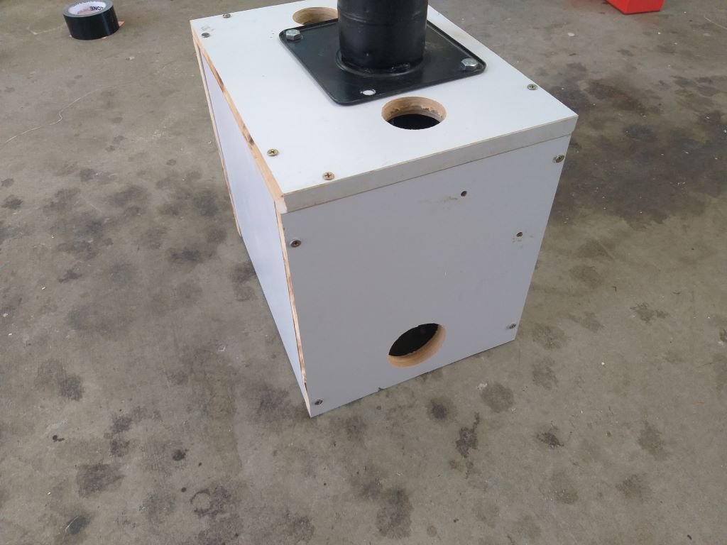
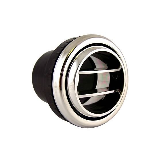
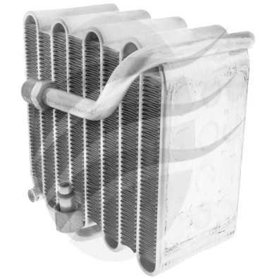
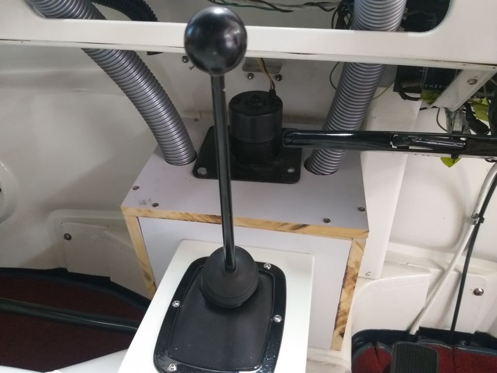
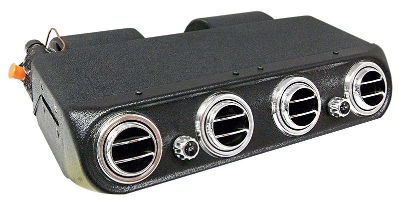
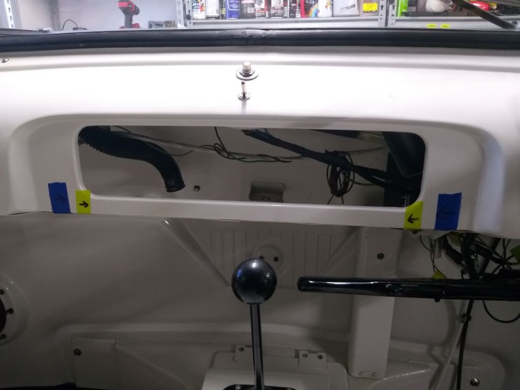
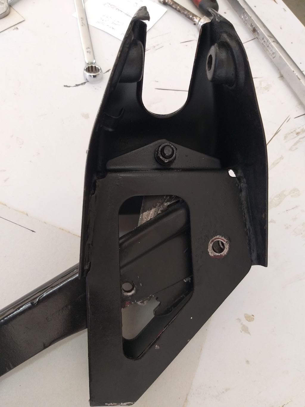
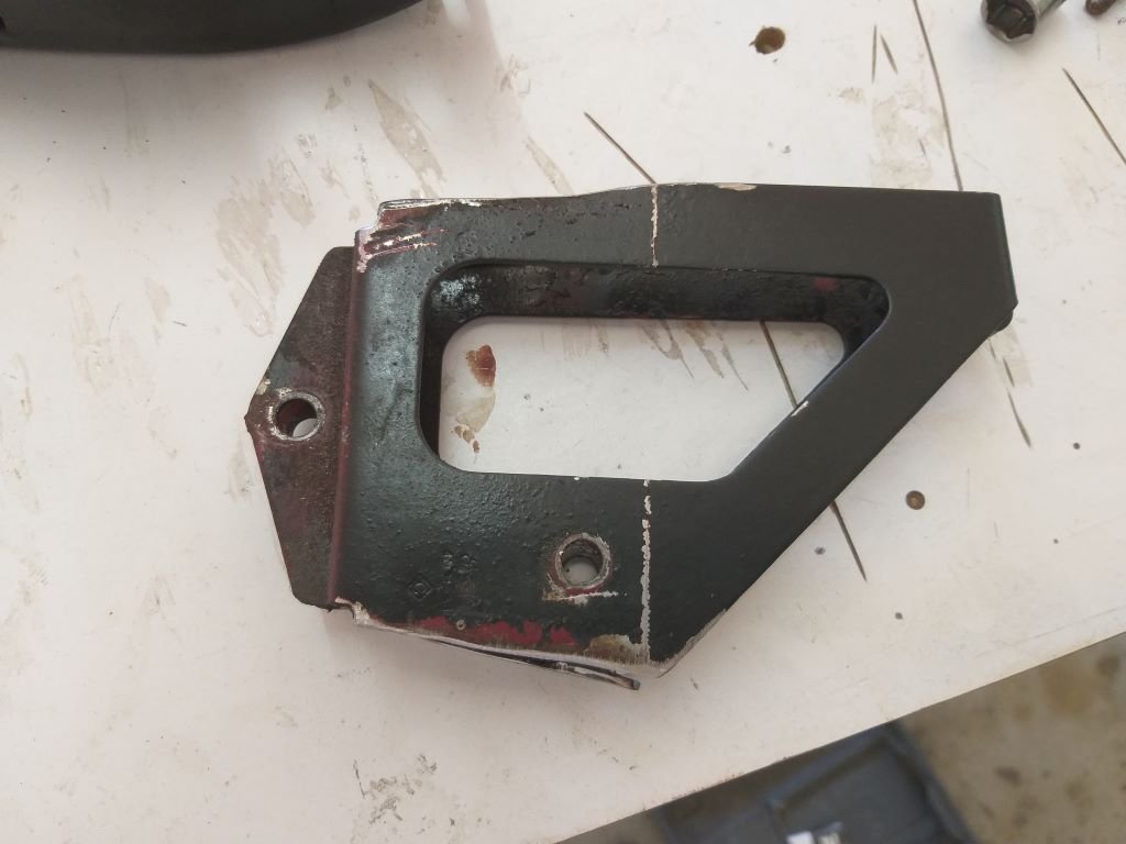
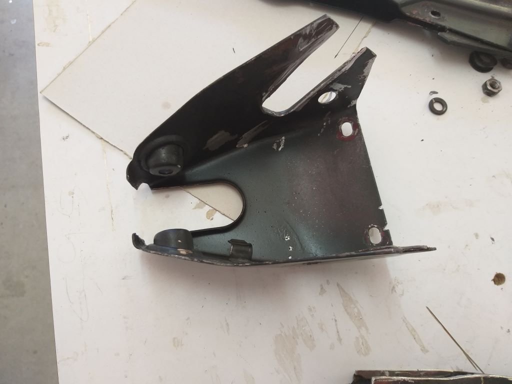
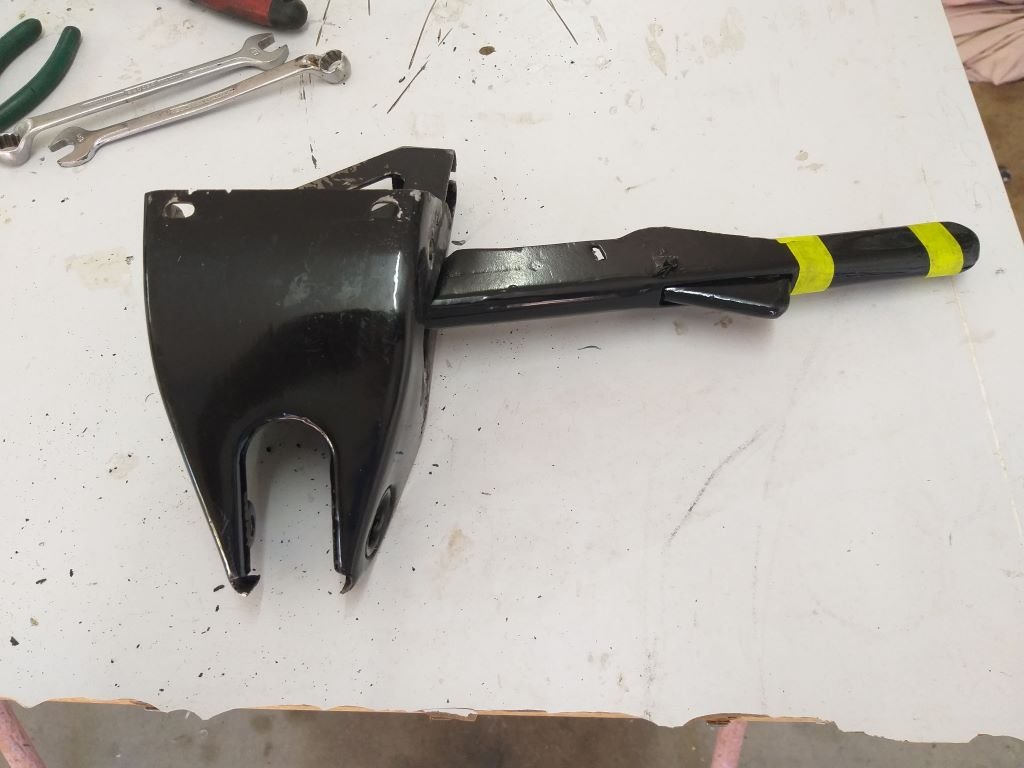
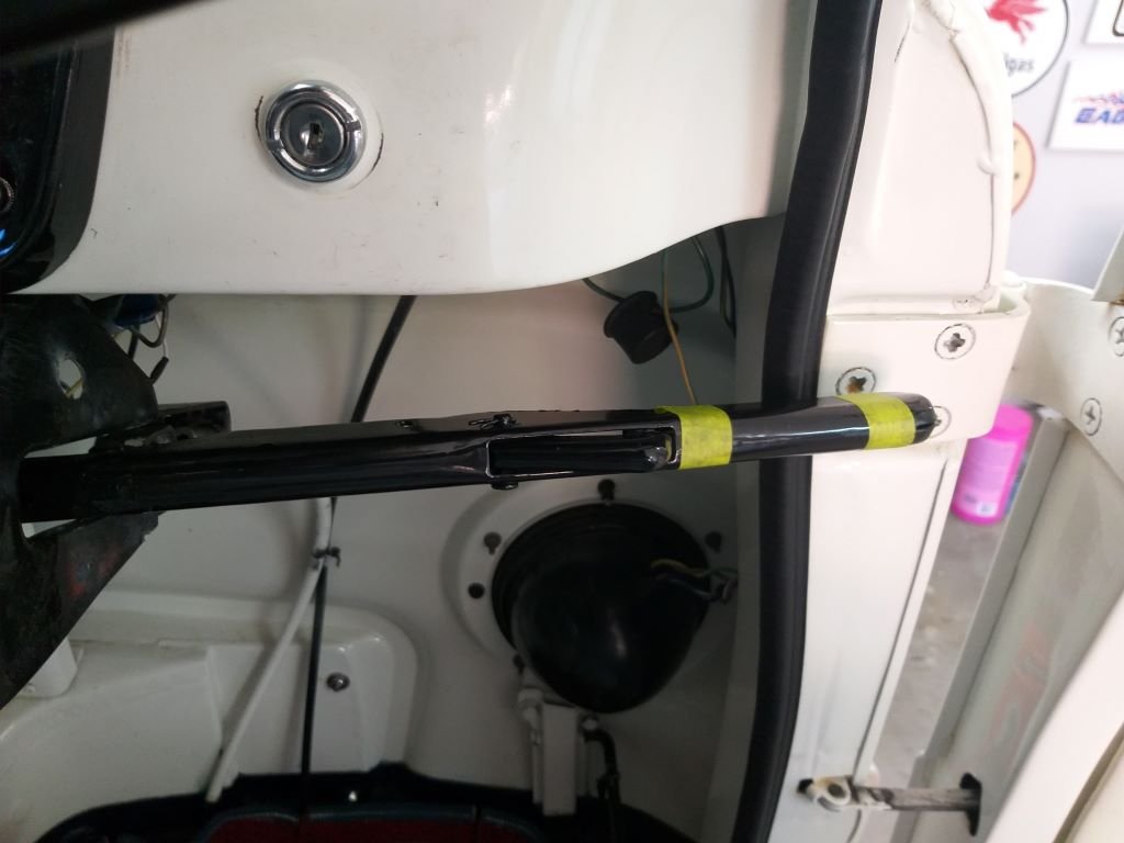
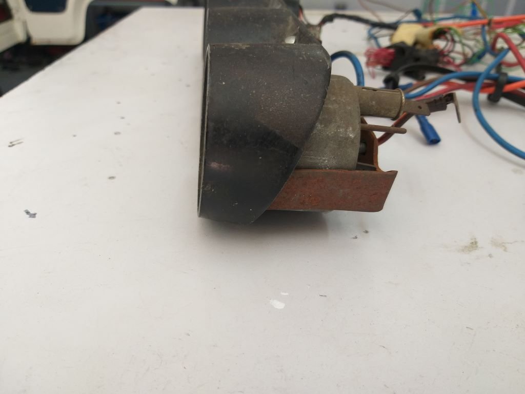
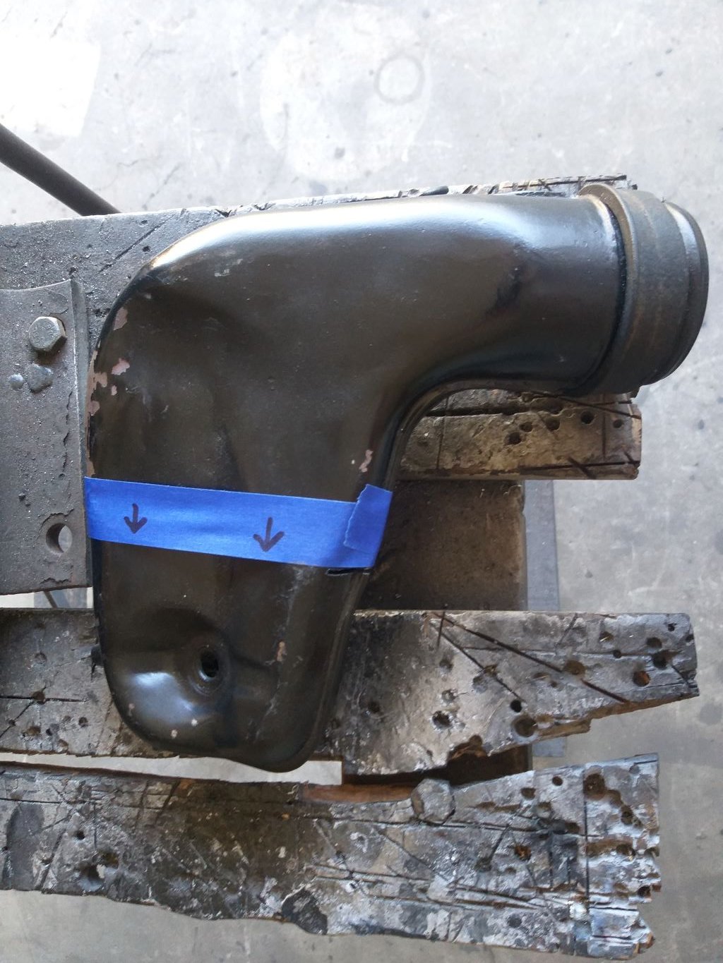
I've asked my mate Cameron to dig around his aluminium offcuts for a long enough piece to make my gauge plate, so I've put that job to one side for now. Turned my focus to the next big-ticket item being the installation of an a/c system. First thing to work out is what I'm going to do for the dash unit. I briefly toyed with the idea of fabricating my own loosely based on the factory option heater unit that was a popular option in colder countries. It's quite agricultural looking and reports are that their operation was piss poor. Looks like so: My plan was to substitute the heater core with an a/c evaporator. I even went as far as to build a grotty looking working mock-up in typical Rough & Ready Restos fashion. I used an old "hamster wheel" type blower motor that came out of the Mustang. It was noisy as hell, but still worked okay. Warm air gets sucked in through some openings down low on each side. The air then passes through the evaporator and cold air exits through the top holes. Here is an image of the evaporator that I was planning to mount horizontally across the box: The cold air would then exit the holes in the top of the box where it would be routed via some slinky pipe to ball type outlets that I was going to fit to the metal dashboard. Even went as far as to place it in position inside the cab. Actual testing of the mock up confirmed that air flow was pretty poor and that was even before fitting a restrictive evaporator coil. I could probably have tried a more powerful / efficient fan to up the flow, but at that point I took my medication and decided to go down a more conventional path. So, allow me to introduce the next option, being an off the shelf under dash unit. Something along the lines of this: The good thing about these units is that they are relatively cheap and work really well. The one fitted to our 66 Mustang is colder than the a/c in our modern Bongo van. However, fitting one of these units is not without its challenges. As per the photo below the unit would be mounted to the underside of the dashboard just below my planned gauge panel and between the taped marks in this photo : The eagle eyed amongst you will immediately notice that the bloody handbrake lever is in the way of the proposed unit. I could offset the unit towards the passenger side thus clearing the handbrake but leaving poor Mrs Flash to freeze her tits off while I swelter on the other side of the cab. Not an option Mrs Flash told me in no uncertain terms. Also, my OCD couldn't cope with that look, so I needed to come up with plan B. Toyed briefly with the idea of fitting an umbrella style handbrake lever out of my mid 80s HiAce donor. Would have been a pain in the butt to adapt and wouldn't have looked half as good as the original Thames unit. So, I discarded that idea too. Then thought about a foot activated mechanism or maybe something hydraulic, but again I stuffed these ideas into the "too hard" basket pretty promptly. Then in the wee hours of the morning I came up with a cunning idea, as you do. So with an extra spring in my step, I skipped off to the shed bright and early this morning. Quickly whipped out the steering column bracket that incorporates the current handbrake lever for a closer look see. Yike, I thought ... I wonder if I can unpick the internal bracket that holds the handbrake lever and flip it 180 degrees. Worth a go I reckoned, so put on my big boy pants and took to it with my grinder of angles and end up with these:: Fizzed them back together and ended up with this: And my handbrake lever now sits on the right hand side of the column. Connected it all up and the handbrake works perfectly. Only issue is that the handle is too long so I can't close the door which is about as useful as a chocolate teapot. Seriously though, I'd taken some measurements beforehand, so I knew this starting out, but I wanted to prove the concept before going as far as hacking up the handle. So, the next step is to do a bit of a "cut and shut" so I end up with a shorter handle that still has the factory rounded end. Stay tuned for the next exciting episode. Thanks for reading.

- 740 replies
-
- 17
-

-
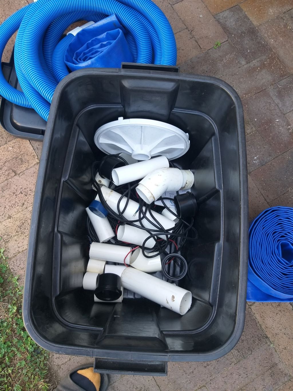
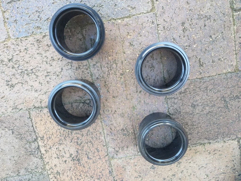
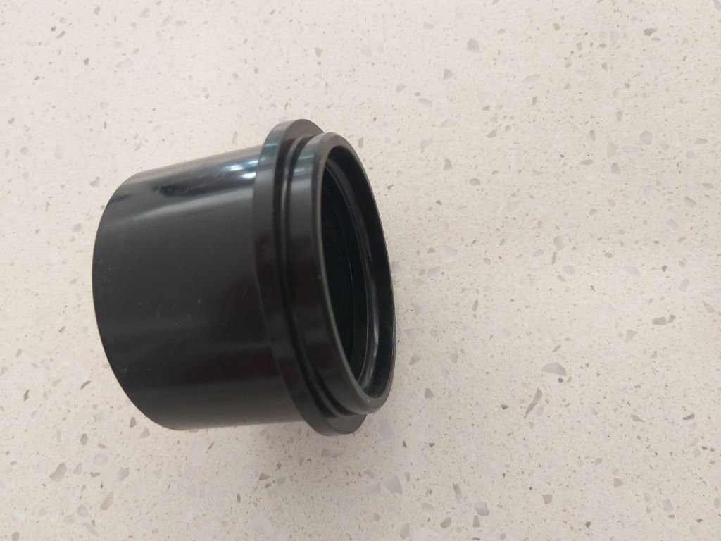
Because I lead such a sad life, the smallest of things cause much excitement and I've just got to share this one with my oldschooler mates. So, a few posts back I was talking about my gauge panel and the fact that I wanted to try and find some slip rings to finish off the 2-inch gauges and my plan was to check out the Bunnings plumbing aisle on our next town trip. Anyway, I'm a self-confessed hoarder of note and earlier this morning I thought I'd rummage through my own stash of plumbing related bits and pieces. Started off by unpacking my two plumbing boxes but didn't find anything suitable. Then I spotted another box that contains left over bits from when we had our pool installed. At the time I remember the pool installers rolling their eyes as I scurried about gathering up all of their discarded bits and pieces, but to me this stuff is gold. So anyway, I dragged the pool storage container out into the sunlight. Popped the lid. Wow, not much of a choice I'm afraid. But, then old eagle eye spotted a few bits of interest. Dug them out for a closer look and couldn't believe my luck. Exactly 4 of these puppies: Rushed back to the garage and grabbed my mock up gauge. Bloody perfect ! And each of them has a magic little side profile that will give me exactly the look that I am aiming for. See, I told you that my life was sad.
- 740 replies
-
- 20
-
-

-

-
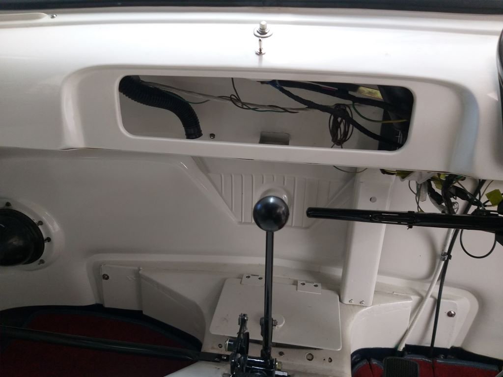
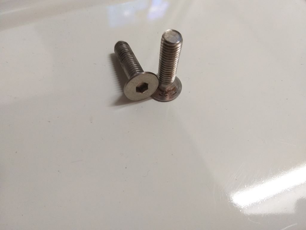
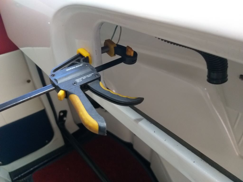
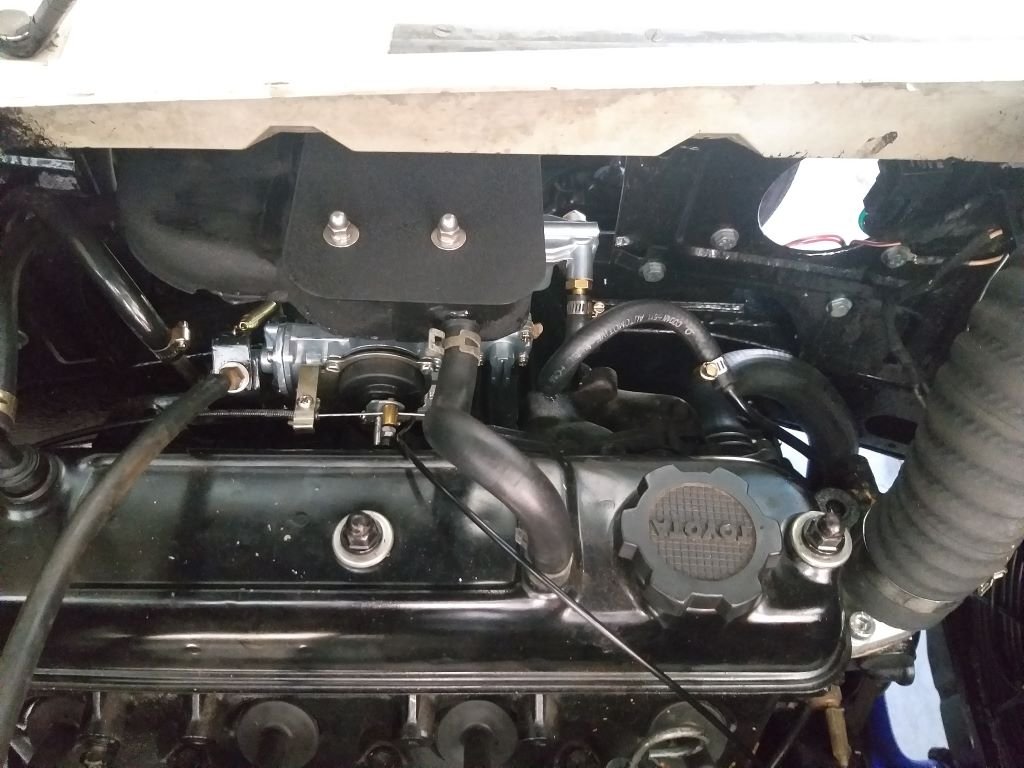
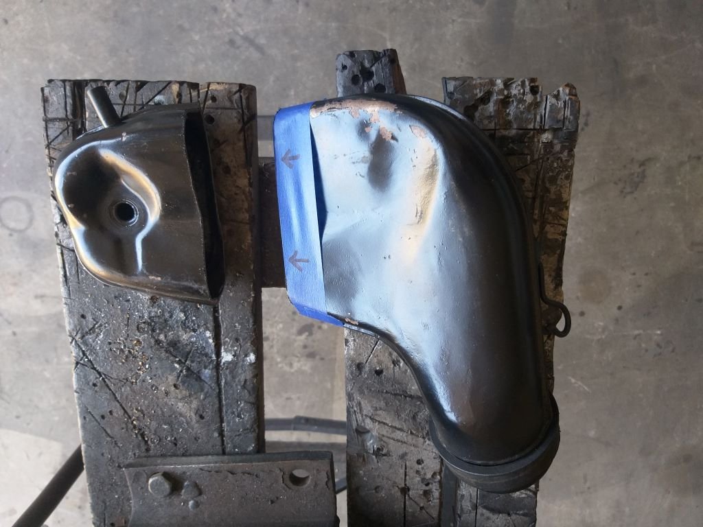
I'm hopping about between jobs at the moment. The paint was dry on my new air duct so I quickly fitted that with some fresh stainless nuts and bolts. Next small job was to figure out a way of mounting my "yet to be fabricated" gauge panel in place. Here is a close up of the opening that the panel will sit in. The easiest thing in the world would be to drill a few holes in the dash and chuck some self-tappers in, but my OCD couldn't cope with that, so I've come up with an alternate plan that involves these two countersunk headed bolts: I mixed up a bit of JB Weld and smeared it all over the head of each bolt, then used a small clamp to fix them to the back of the metal dash until the glue goes off. I'll then make the inner panel longer than the opening with holes drilled to pick up the bolt positions. Hopefully they will be strong enough to hold the panel in place. I'll then cut a second panel in the shape of the actual opening which I will bond to the inner panel thus bringing the actual face panel in line with the rest of the dashboard. It looks okay in my head at the moment, so hopefully it will turn out just as good when I've actually made it.
-
Thanks for posting the photo Bryan. If you didn't know any different you would think that was a factory "GT" option. Doesn't look out of place at all.
-
That looks bloody good.
-
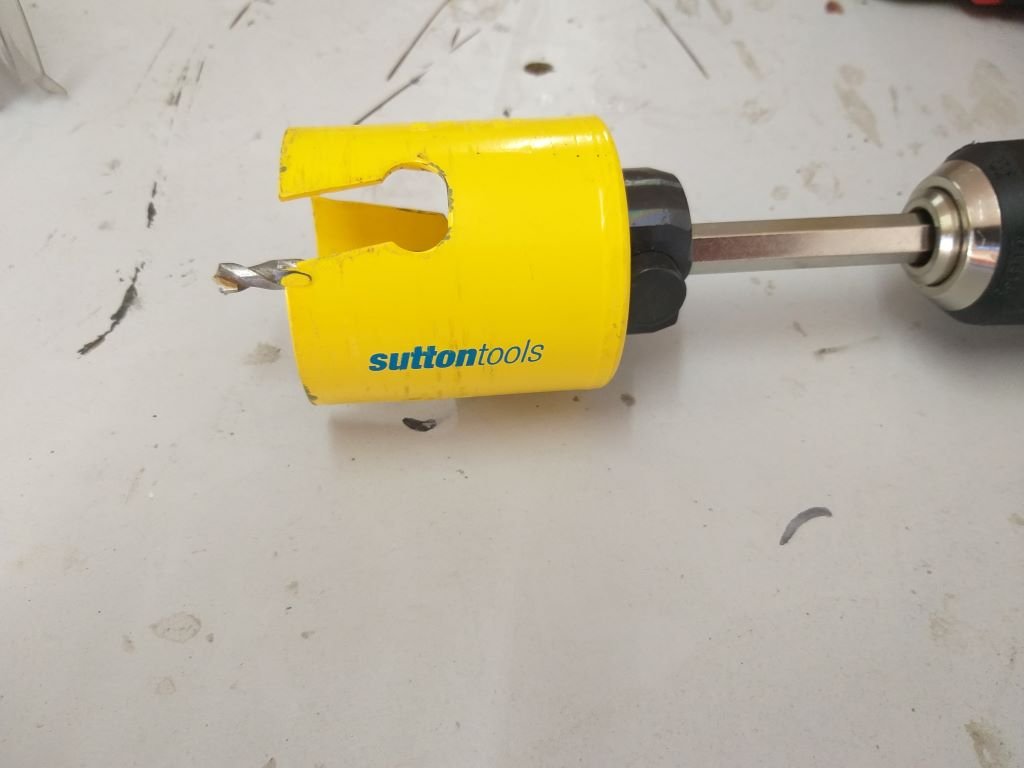
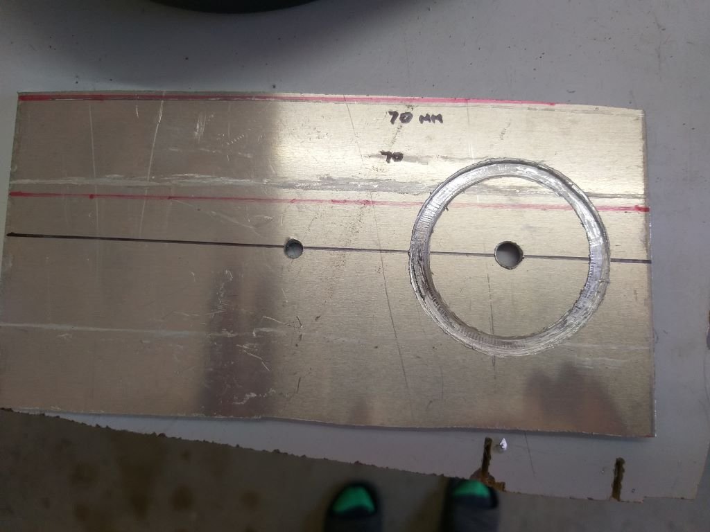
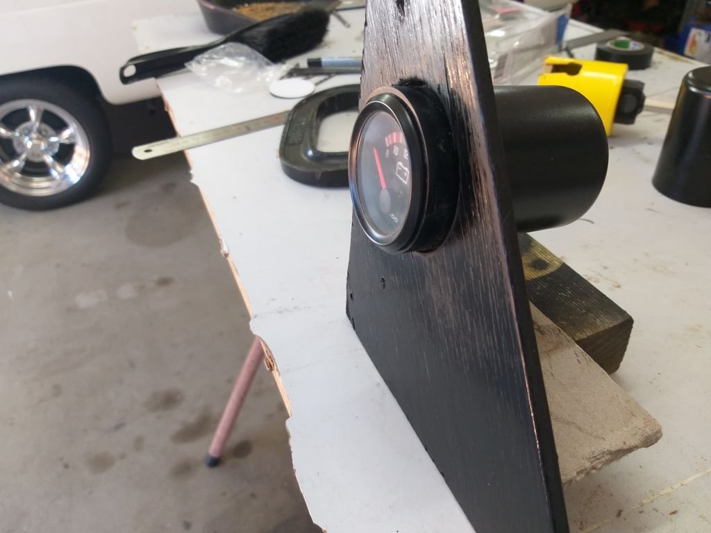
Continued working on my gauge cluster setup. The outer diameter of the plastic gauge pod is 60mm and it just so happens that I have a 60mm hole saw left over from our house reno. Played around with a few offcuts. First up was a bit of 3mm aluminium plate, but the poor old hole saw took a bit of strain, so I'm thinking of using something softer. Next up was an old scrap of plywood. Much easier to cut, but I'm not so keen on the woodgrain. Cut one anyway and set it up with the pod to get the feel. So, ignoring the woodgrain issue for the moment, I focused on the rest of the look. The hole saw leaves a slight gap which will need filling. Not that easy to achieve when the distance between gauge pods will be around 10mm. But I'm thinking that if I was to find a bit of PVC pipe that the gauge pod could slip into, then I'd be able to create some slip rings that I could push over the pods from the front. This would fill up the gap and also if I made the slip rings long enough, they would give the gauge the "countersunk" look that I am aiming for ala the Cortina GT gauge panel. I'll scratch around the Bunnings plumbing aisle to see what I can find next time we are in town. In terms of dealing with the woodgrain I'm thinking that a piece of veneered ply might do the trick. I'll rummage through my wood pile tomorrow to see what I can find.
-
Thanks for posting those photos Bryan. Definitely the first time I've seen that setup. My mate Grant has a few MK2 GTs in his collection, but the gauge cluster looks quite different to the GTE. I always fancied this look. My first car was an Anglia 105e and back in the day you could buy a fibreglass dash for the 105E that mimicked this setup, but I was just a peniless school boy so I ended up making a gauge pod out of plywood that I covered in vinyl and then slapped it onto the Anglia dash with a few self-tappers. I thought it was the dog's bollocks.
-
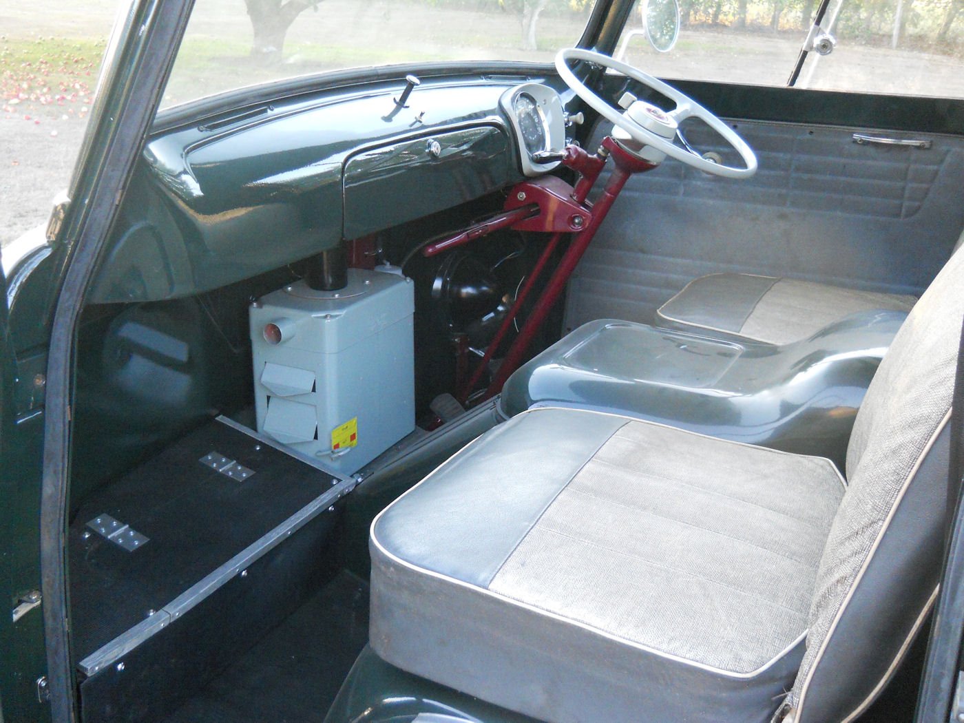
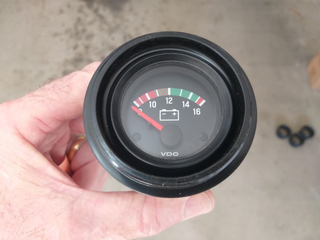
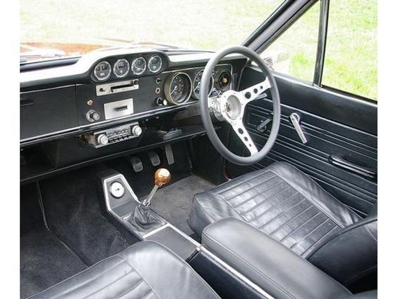
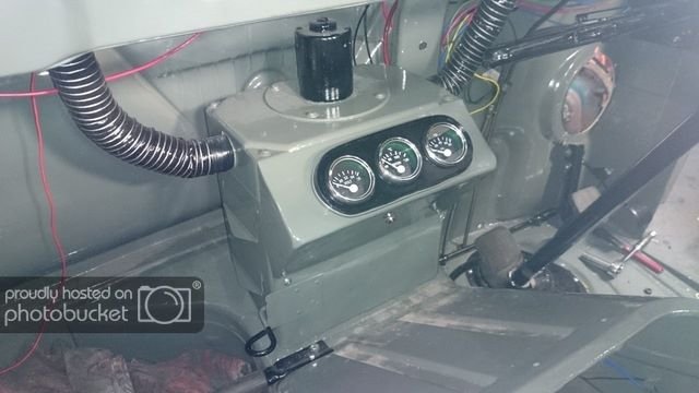
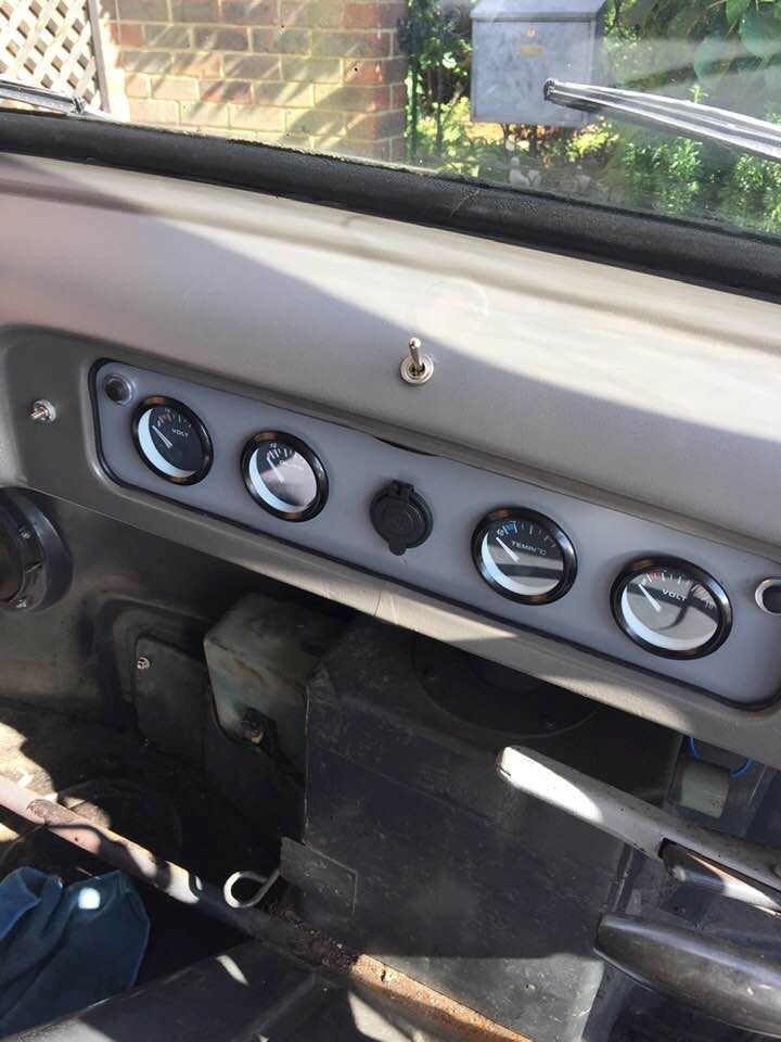
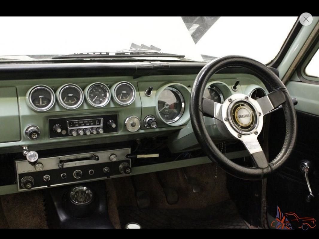
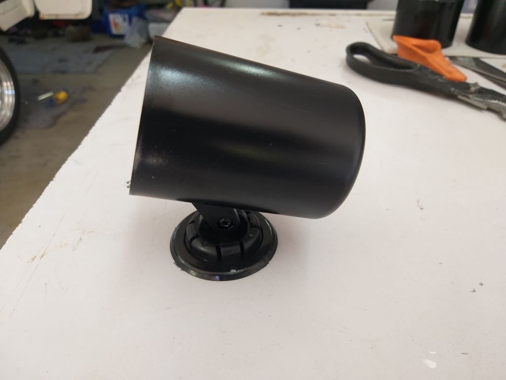
I'm back in a holding pattern while I wait for the hydraulic man to slot me in for my new power steering hose, so I thought I'd make a start on the next item on the list namely the fitting of extra gauges. My current thinking is to fit four extra 2 inch gauges if I can. These being a water temp gauge, a voltmeter, an oil pressure gauge and lastly a rev counter. Looking at what other Thames owners have done, there are a few options. This image shows an instrument cluster that has been attached to the factory option heater box: Whilst I currently don't have a heater box one of my future plans is to fabricate a similar looking box to house my a/c evaporator, so fitting a gauge pod like this could be an option, but in my case I now have the floor mounted gearshift which would clash with this. So, for this reason I've excluded this as an option. The next option is quite a popular one and involves replacing the open glove box with a flat panel that allows for the fitting of extra gauges, switches and the like. Just like so: I'm currently leaning towards this setup. The only thing that I don't like about it is that it looks homemade. I'd prefer something that looks like it could have been a factory option. I then remembered that the old Cortina MK1 GTs had a nice setup, that looked like so: It just so happens that my mate Grant has a couple of Cortinas and he had a spare GT cluster that he lent me. However, on closer inspection the GT gauge pod has an angle built into it which wouldn't suit a flat panel. There is no way that I was going to hack up a rare GT cluster just to make it fit, so I came up with a plan B which involves using 4 cheap plastic gauge pods that I will poke through a flat mounting panel to create a similar look to the GT cluster. eBay delivered up 4 of these beauties earlier in the week, so it's time for me to make a start.
-
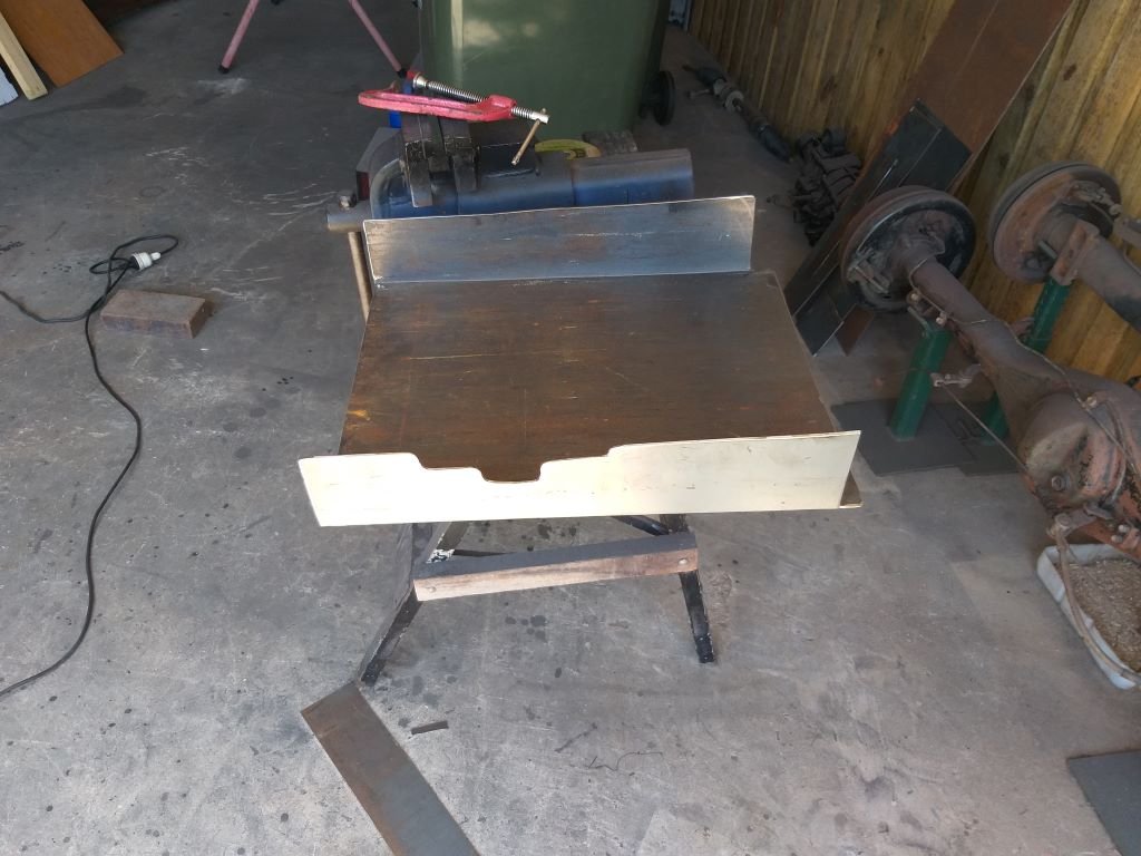
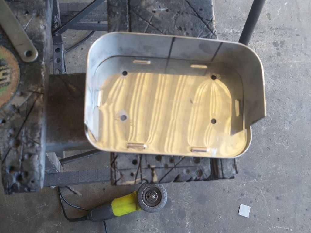
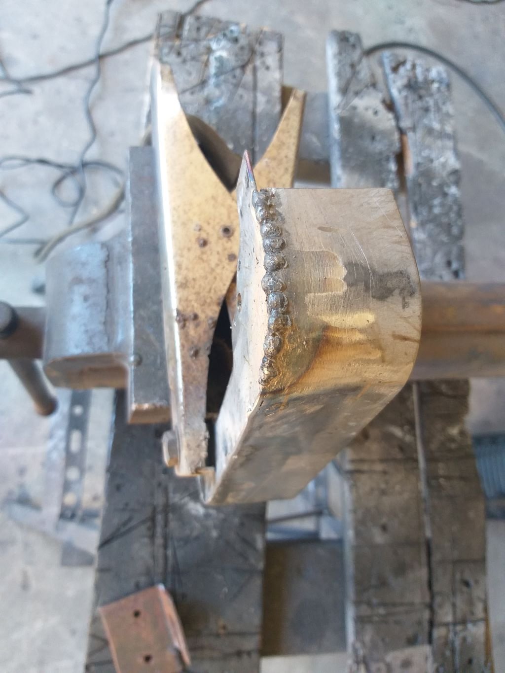
Started off the day by chucking a bit of weld to strengthen up the folds. Hit it with a flapper disk to mask my ugliness. Then a quick spritz of satin black. Looks half decent.
-
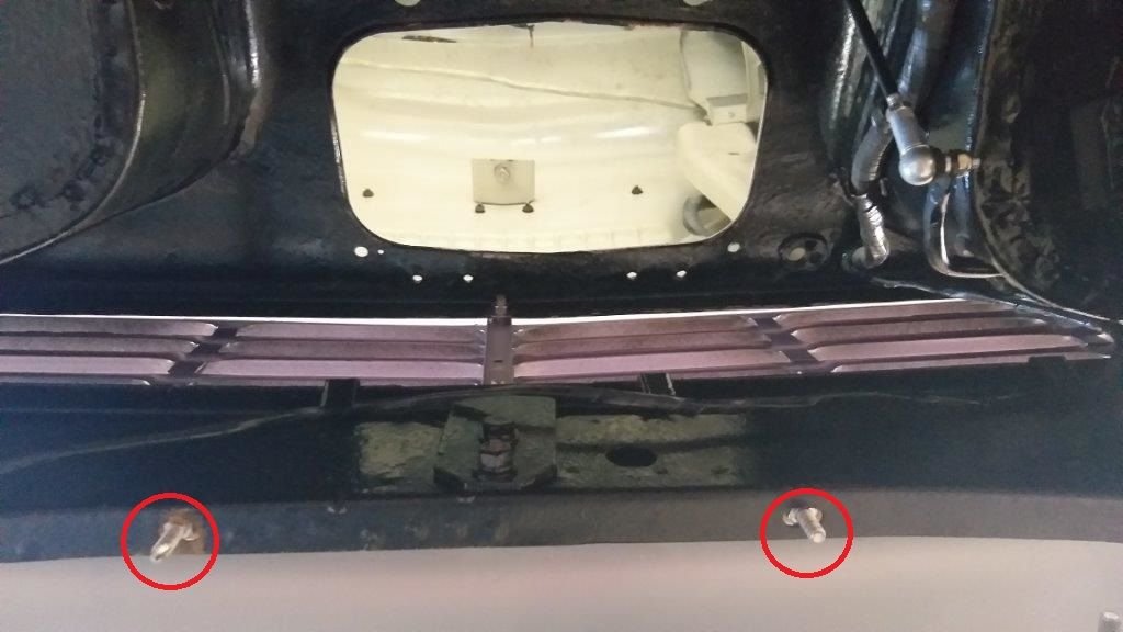
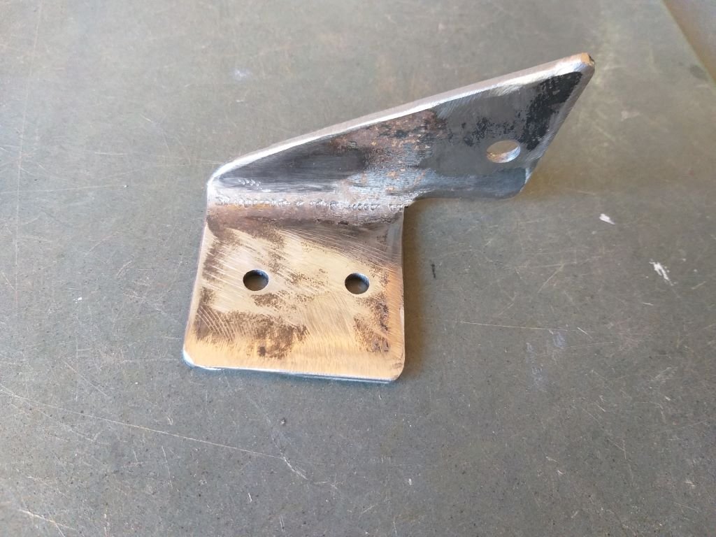
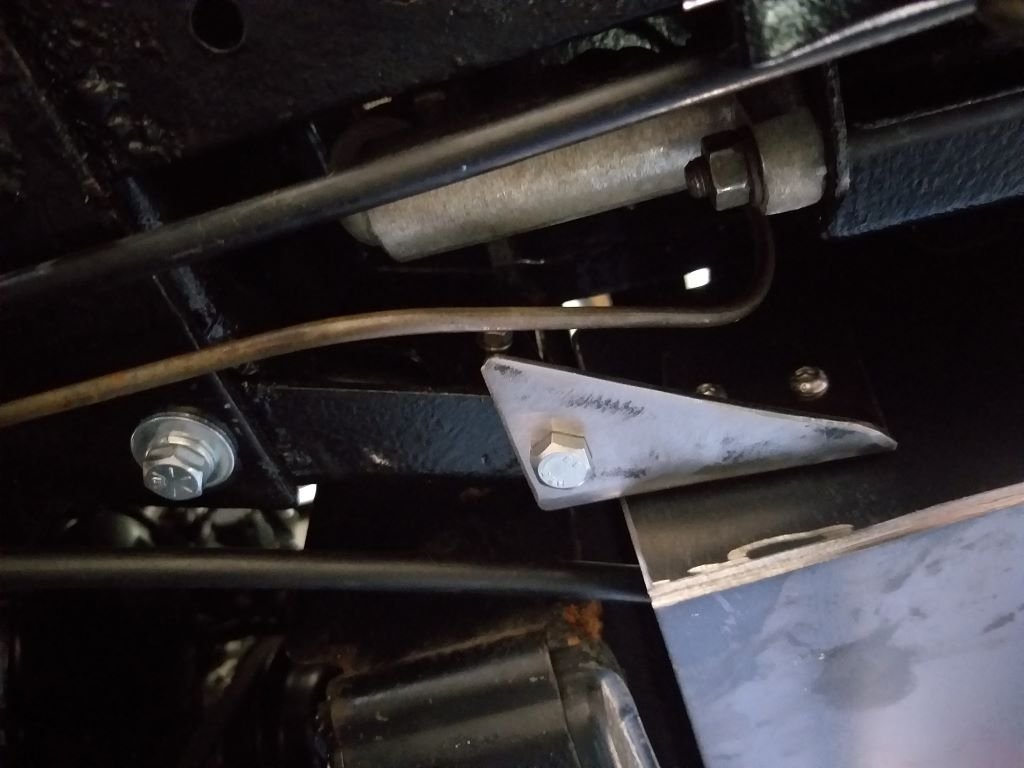
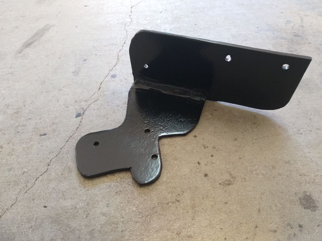
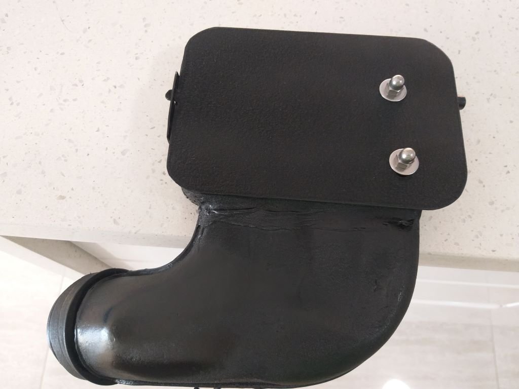
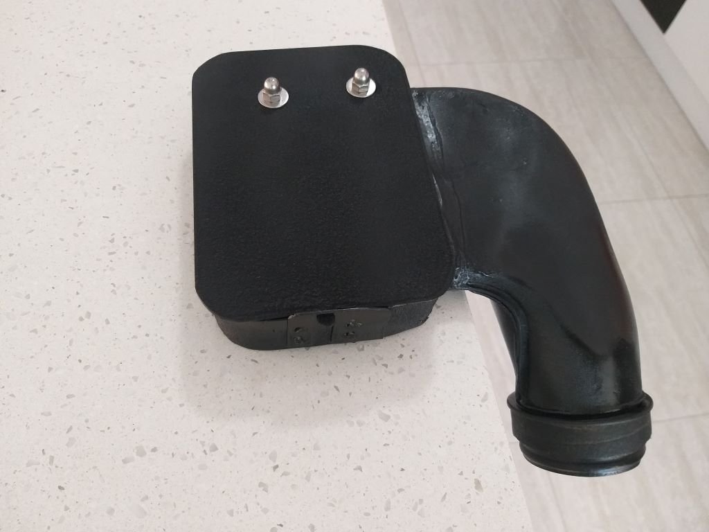
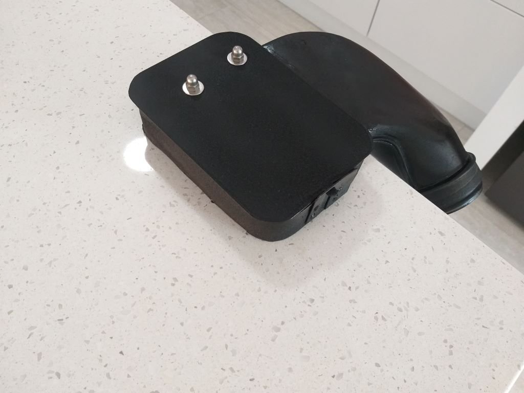
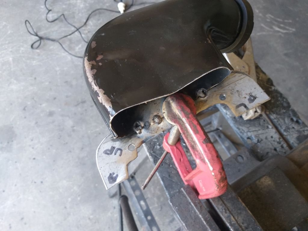
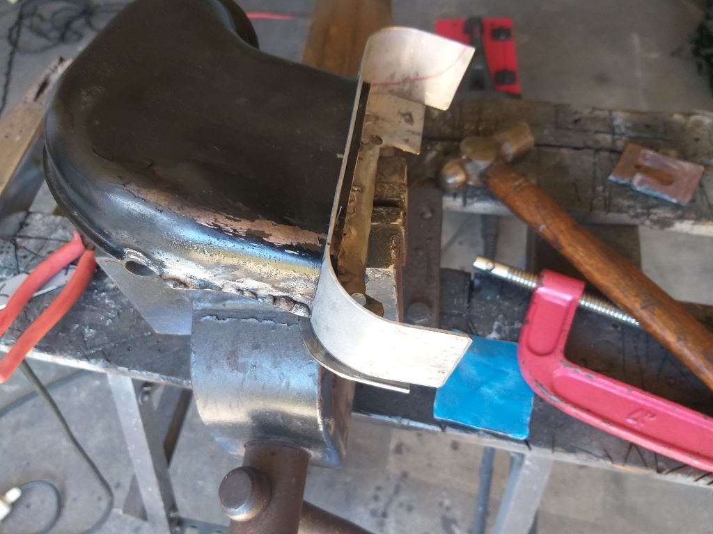
Today's focus was on the fixings for my newly fabricated air deflector. Bolting up the front of the deflector was easy as my plan was to use the factory mounting points on the valance where the original deflector was fixed. The rear fixings for the factory deflector were on the original Thames cross member, which is no longer, so I had to get creative. Luckily two of the chassis based mounting holes for the original cross member looked to be positioned perfectly for the task. All I had to do was fabricate two little mounting tabs. Started off with some CAD work: Which I replicated in steel. And the test fit went off without a hitch. Tomorrow I'll run a bead of weld along each fold just to beef things up where I scribed the plate. Then a quick clean up followed by a spritz of paint and that will be another item ticked off the list. Thanks for looking.
- 740 replies
-
- 14
-
-
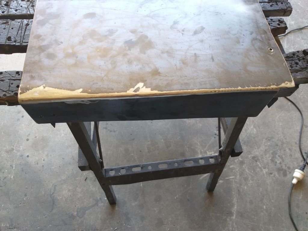
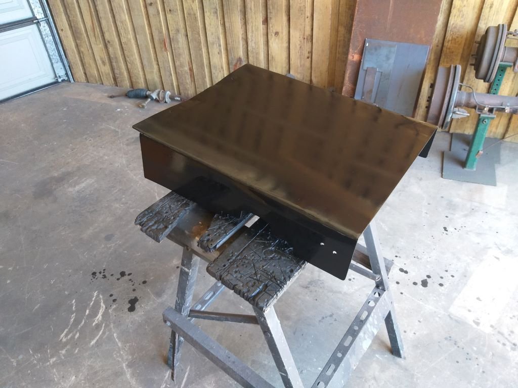
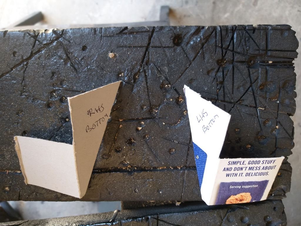
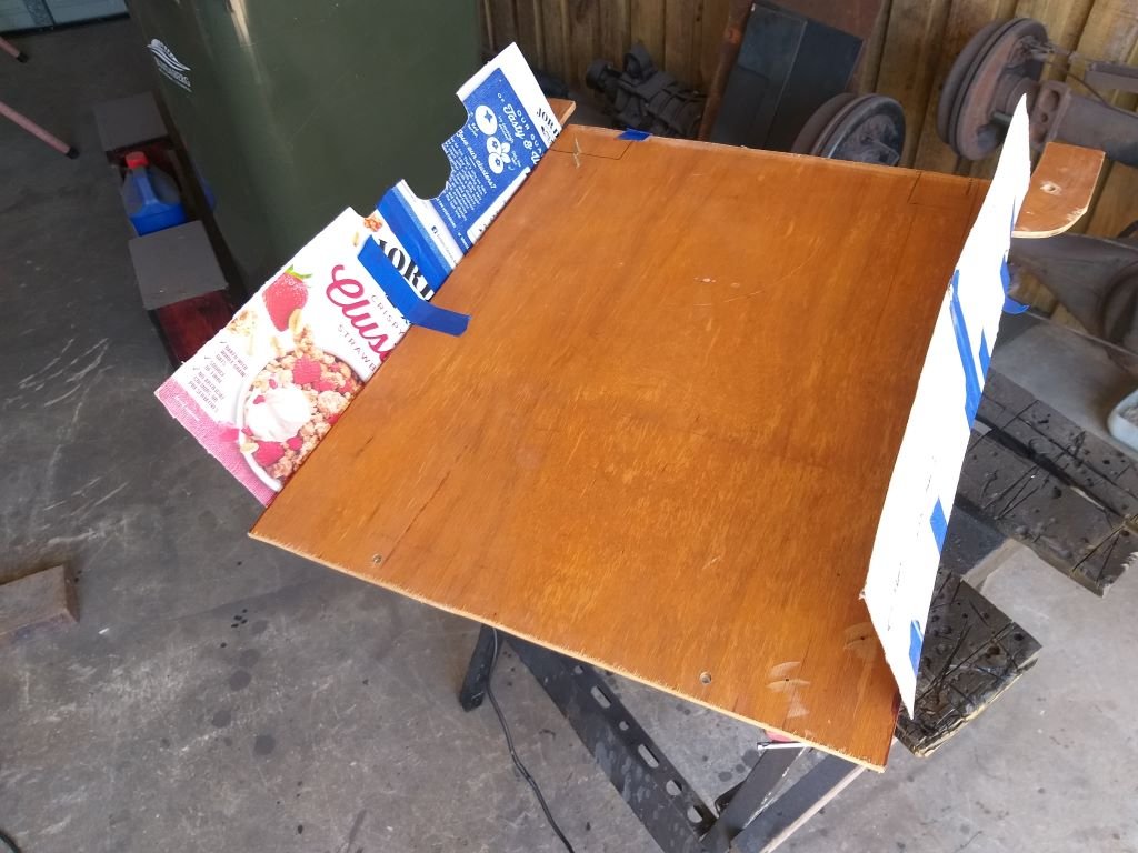
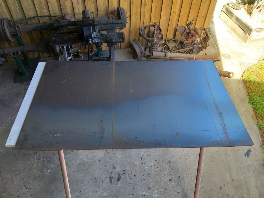
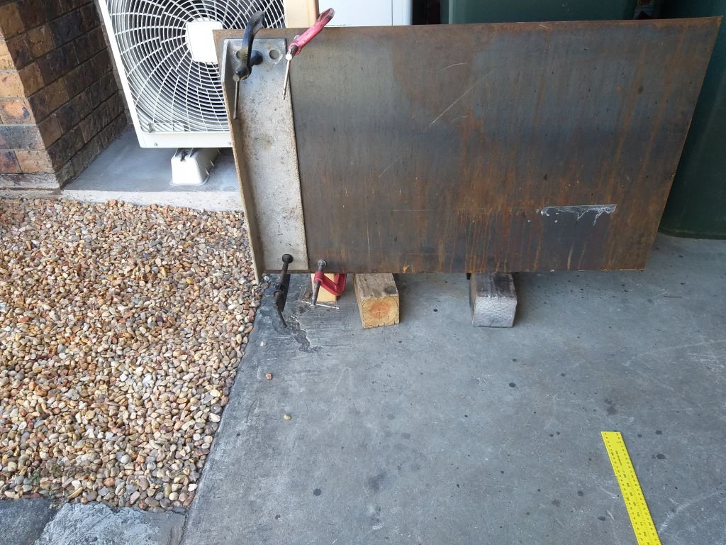
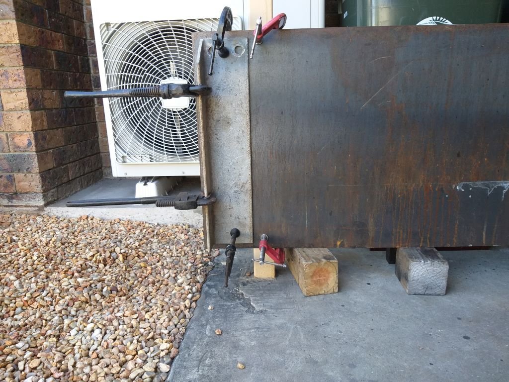
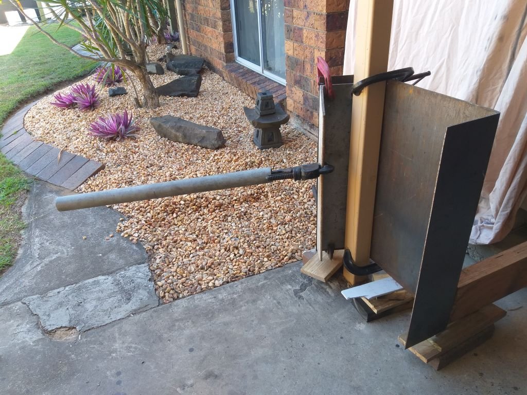
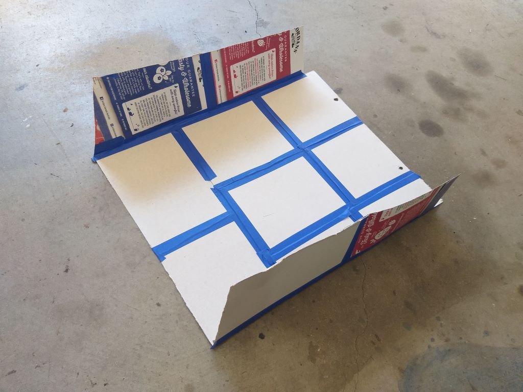
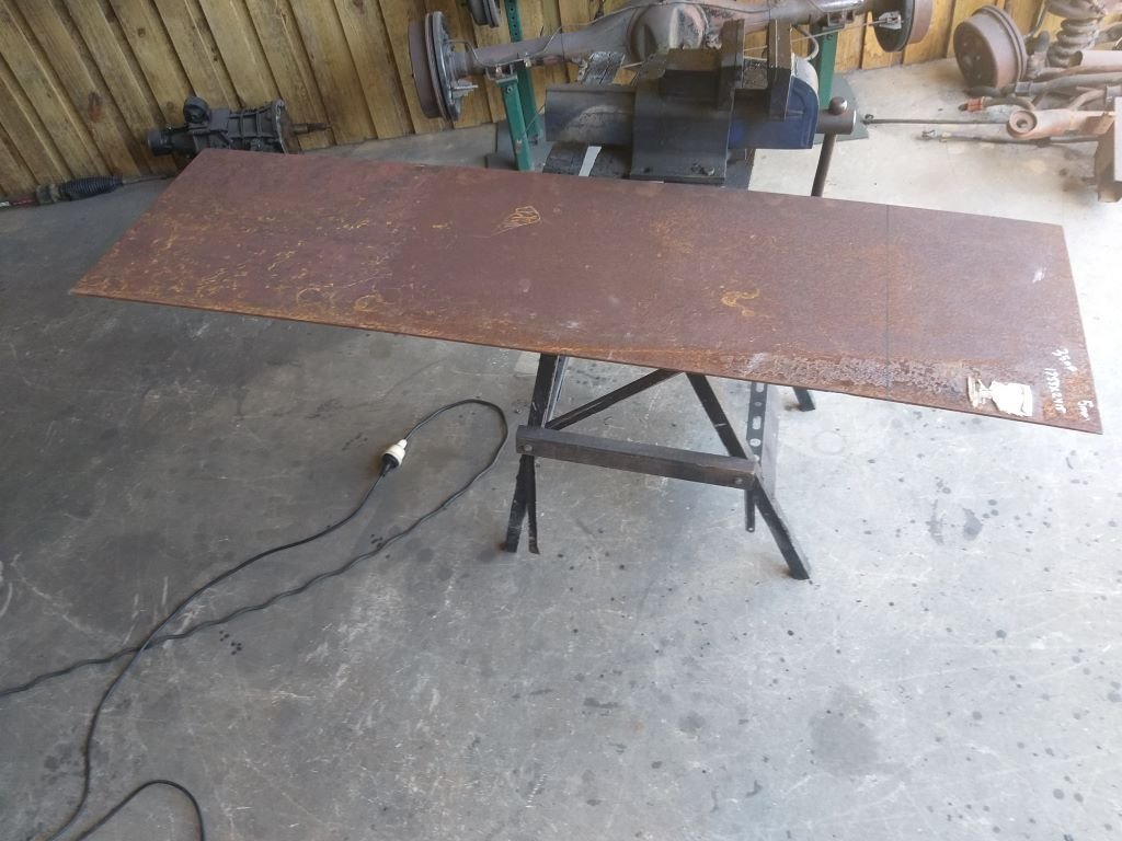
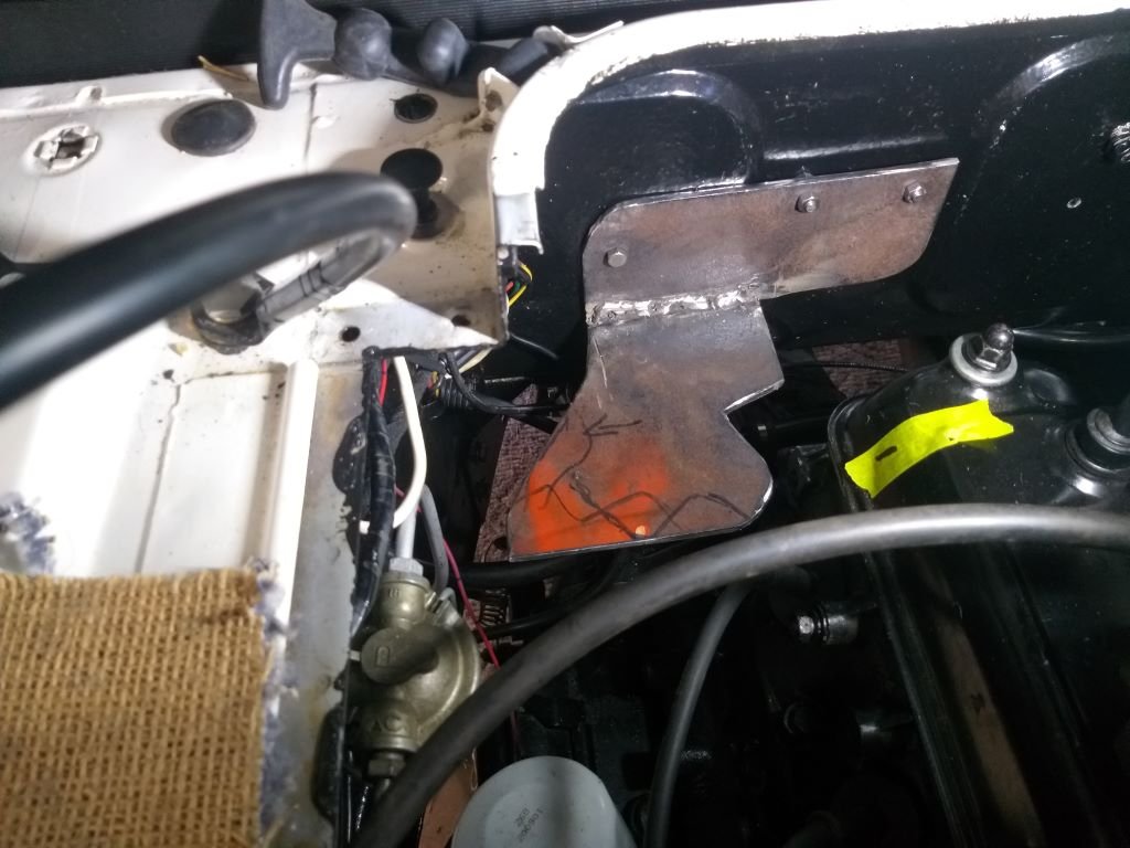
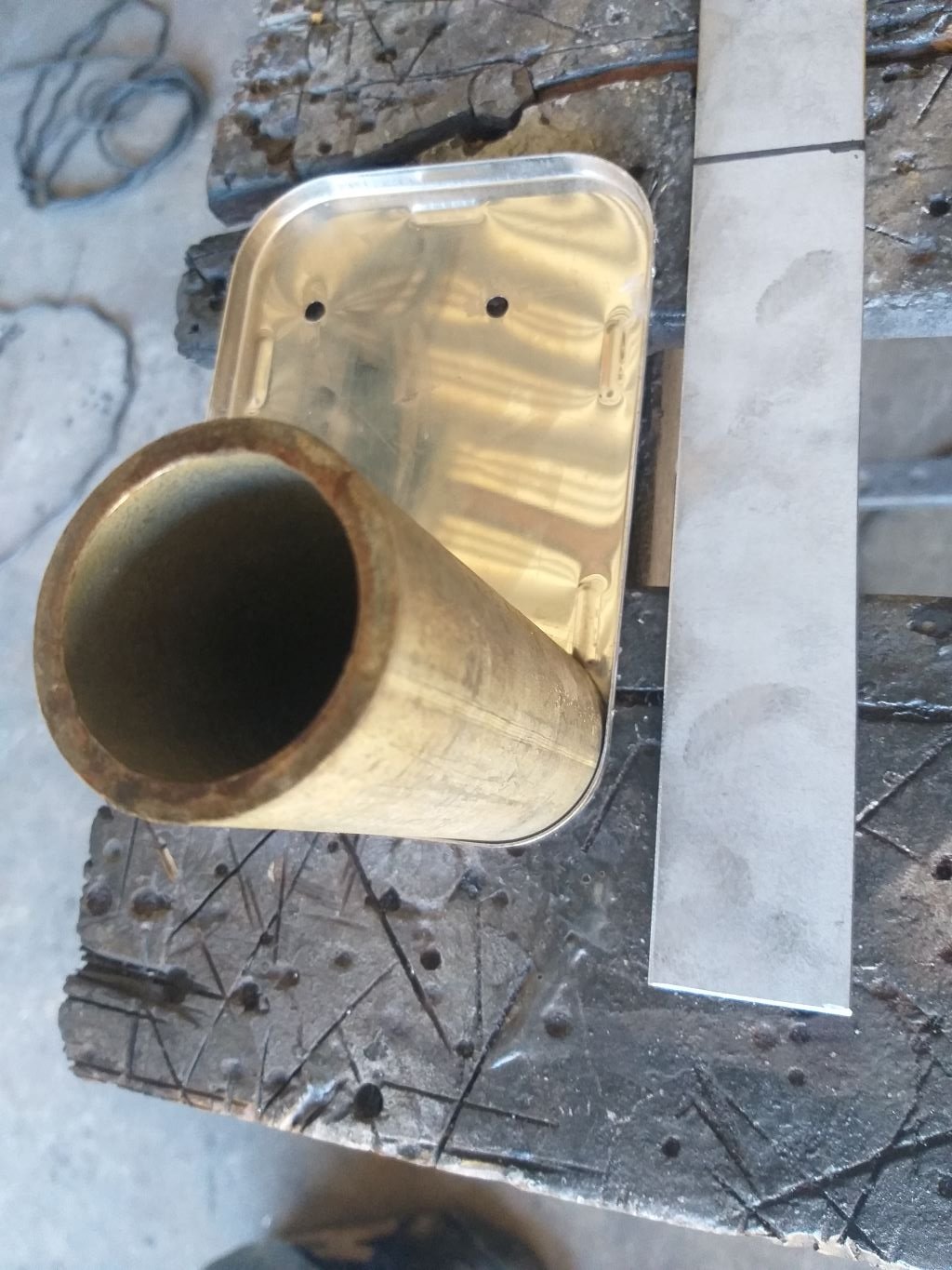
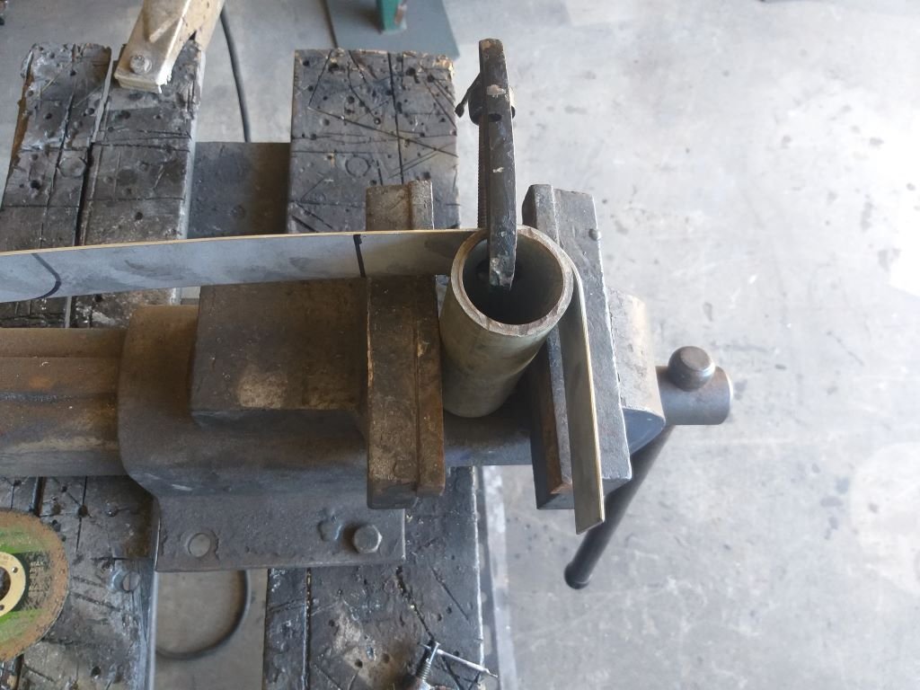
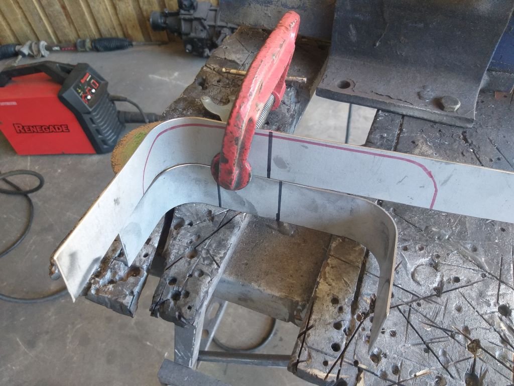
Created a second air deflector mock-up using an old piece of plywood which made it rigid enough to create accurate side profiles in cardboard. The funky shaped cutout on the driver's side upright is needed to clear the floor mounted high beam switch. A test fit proved successful, so I rummaged around in my sheet metal bin, but sadly I didn't have a piece of flat plate big enough, so yesterday we did a trip into town and I picked up this 1.5mm thick beauty: Had to figure out a cunning way to fold up the main shape. After a bit of head scratching, I decided to use one of the steel posts that hold up the roof for our back carport. Gave the plate a bit of a score and then clamped it to the post with an old bit of angle iron attached for leverage. My two big pipe wrenches and a handy piece of thick-walled steel pipe for extra leverage and my bender was ready to go. And then there was this: Gave the sides a bit of a trim and then carved the little notch to clear the high beam switch and she is almost ready for a test fit. Tomorrow I'll poke a few holes for mounting up front and then I need to create some mounting brackets to attach the rear of the duct to the chassis. Thanks for looking.
- 740 replies
-
- 13
-
-
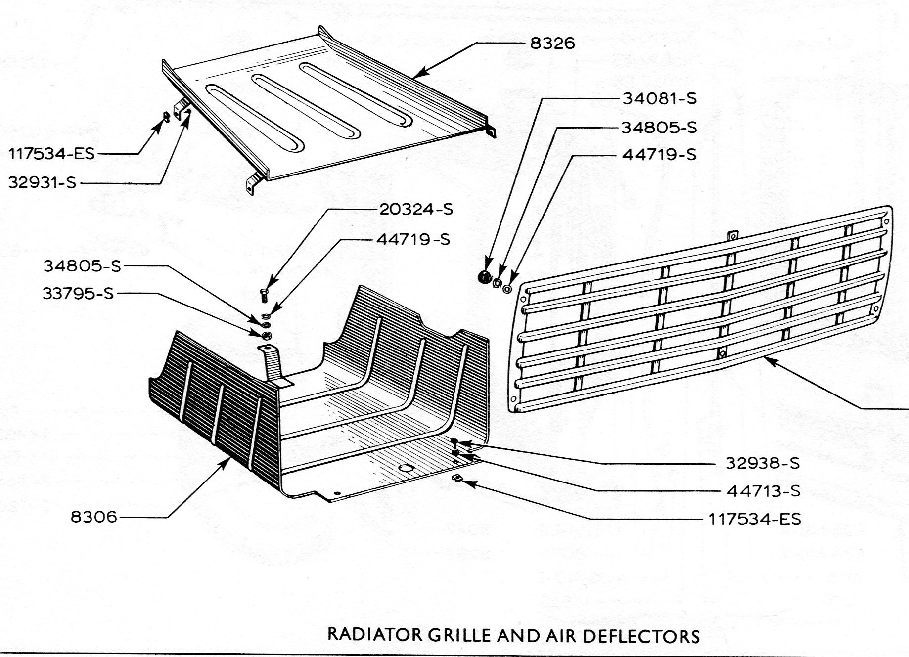
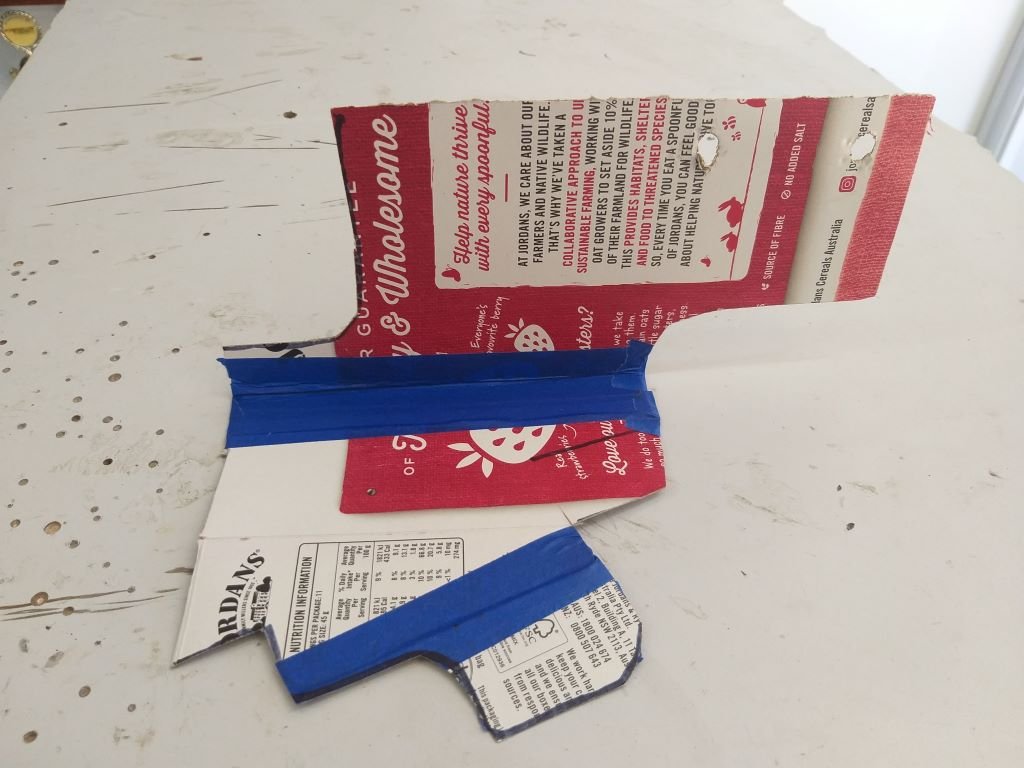
A few weeks back I was swapping a few yarns with Sandy who until recently headed up the UK based Thames 400E Owner's Club. Somehow, we got onto the subject of engine cooling and in passing Sandy mentioned a U shaped lower air deflector plate that was fitted from factory to all of the 400Es with the flat upper deflector plate only being fitted to vans exported to hotter climates. He immediately had my attention as my van has only ever sported the upper deflector plate. Sandy shared this image with me: Back in the day the UK boys used to run a standard Thames radiator to cool their mid mounted V8 conversions with many of them running no helper fan at all and never experienced cooling issues. Granted the UK is a lot cooler than Straya, but I've noticed that my van runs a little warmer than I was expecting and I'm thinking that its likely due to the missing air deflector. So while I'm in a bit of a holding pattern while the paint on my Astra pump brackets dries, I figured I'd make a start on my air deflector. Started off with some rough looking CAD work: CAD is a bit floppy, so the plan for tomorrow is to create a copy in plywood as a rigid mock-up. Thanks for looking.
-
Gave my rough looking Astra pump base bracket a bit of shaping followed by a light spanking with a flapper disc and lastly a little spritz of satin black. Will let it dry overnight and I can then slap it all back together tomorrow.
-
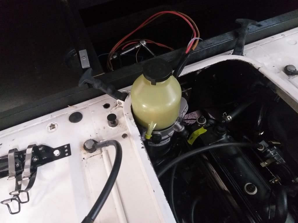
Poked some more holes that allowed me to bolt the original Astra mounting bracket to my newly fabricated bracket. Took a few goes before I managed to get everything in place with just a smidge of clearance all around. Closed the engine lid and the top of the reservoir just clears. Sheesh, she's a tight one as the bishop said to the actress. Tomorrow I'll pull the brackets out for a bit of beautification.
-
Took a trip into town yesterday to pick up a fresh roll of welding wire and grabbed a bit of 5mm plate from my local scrappy. It's a bit crusty but nothing I can't sort out. Did a bit of cutting, did a bit of welding, poked a few holes and we have the rough makings of a mounting base for the Astra power steering pump. More tomorrow.
- 740 replies
-
- 11
-
-
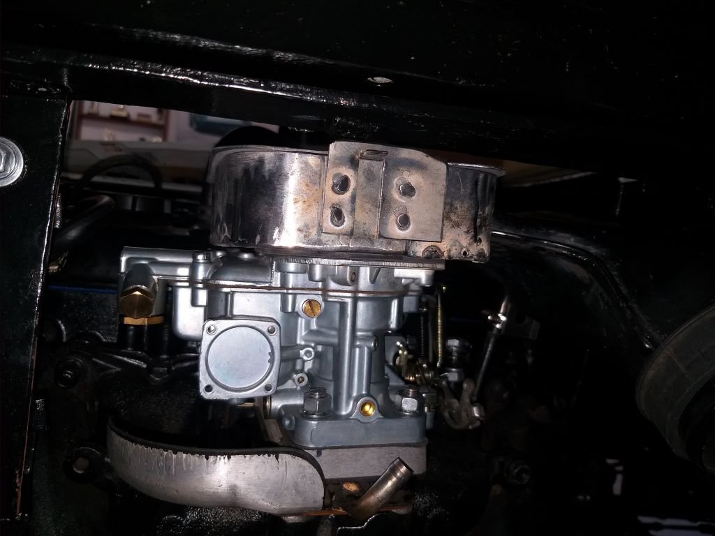
Finally fitted the new carby hat and bolted the removable engine box side back into position. Looks almost like a bought one.
- 740 replies
-
- 10
-
-

VK304's 1988 Nissan Vanette w/ added SR20DET
Flash replied to Willdat?'s topic in Project Discussion
Front looks bloody awesome. I vote white. Reckon it will look killer next to the black bumper. -
Well, that's the carby hat ready to rock and roll. It took a bit of time to grind down all of my crappy welds. I cheated a bit and used some JB Weld to smooth out some of the really grotty looking bits. Also used a ripple coat which has masked some of the ugliness. Final step was to add two stainless steel washers and matching nipple caps for that extra bit of bling.
- 740 replies
-
- 14
-
-
-
Only had a few hours in the shed today so spritzed the final coats on the carby hat. I should be able to present it to you in glorious technicolour tomorrow. In other news I've been fine tuning the Astra pump bracket. It had a little angled section that was quite close to the engine and didn't seem to be serving any purpose. So, I pulled a bit of a van Gogh move and the little ear is no more. Have replaced it with a straight piece since taking this photo: I then tackled a bit of CAD and I now have this pattern for the bracket that will bolt up to the rear wall of the engine box: I've run out of welding wire and I don't have a big enough piece of steel plate to create my bracket, so it's off to town I go tomorrow for some extra supplies.
-
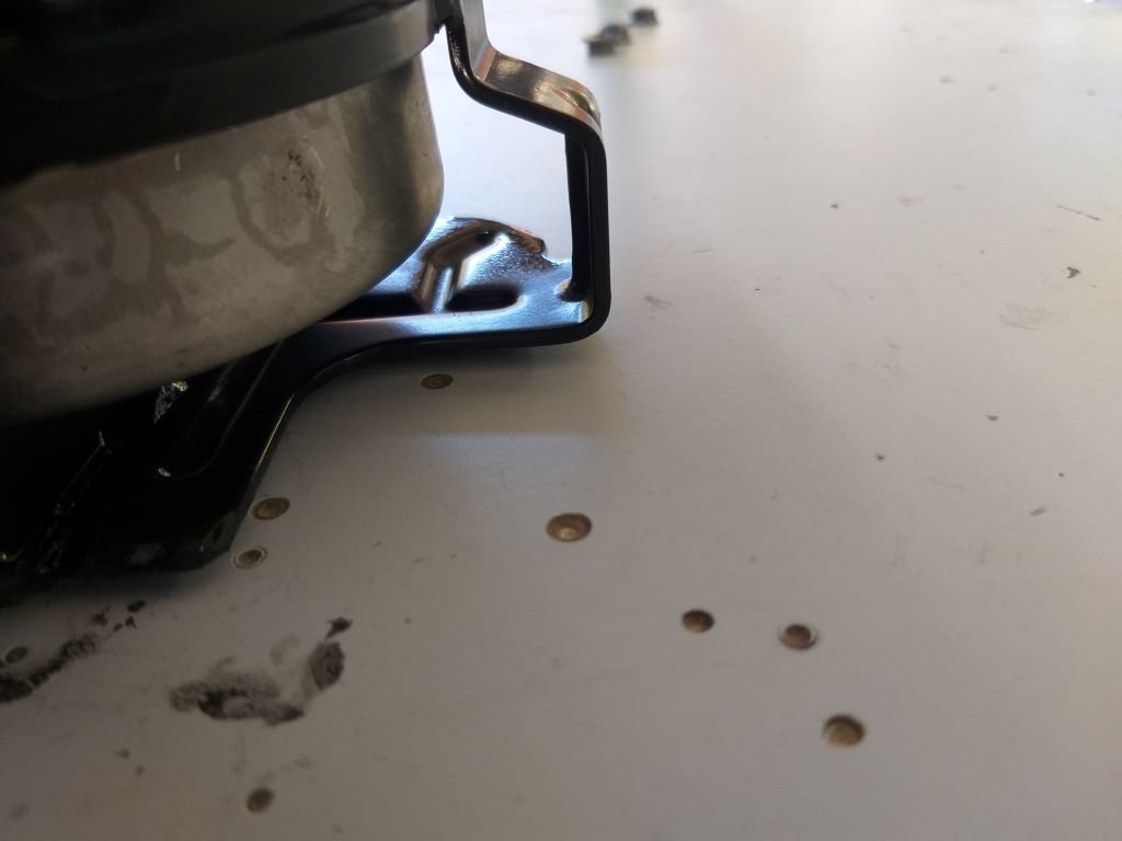
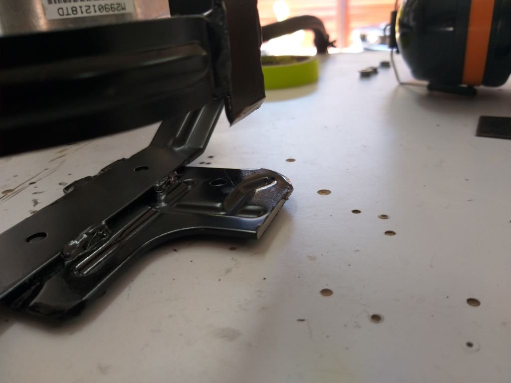
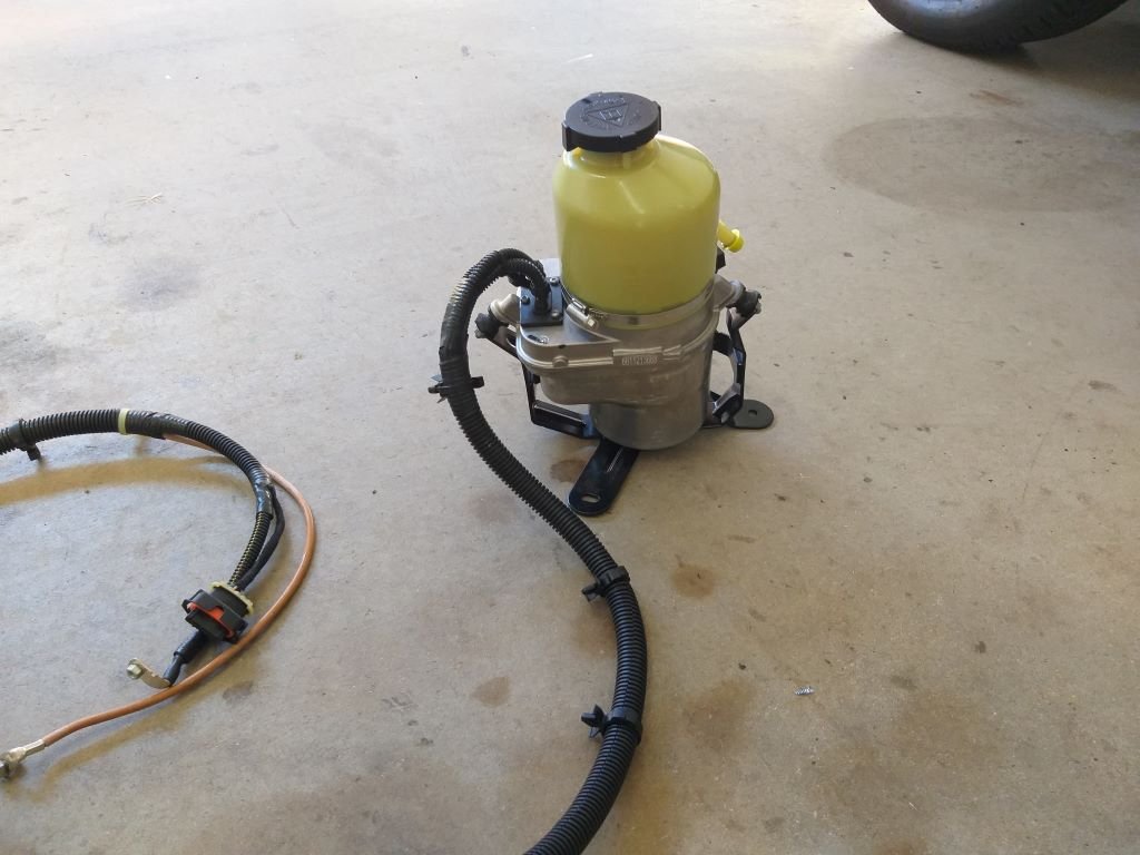
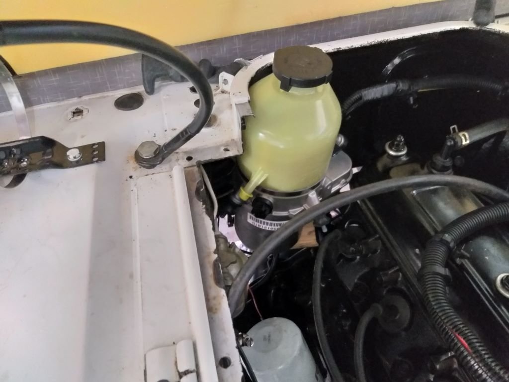
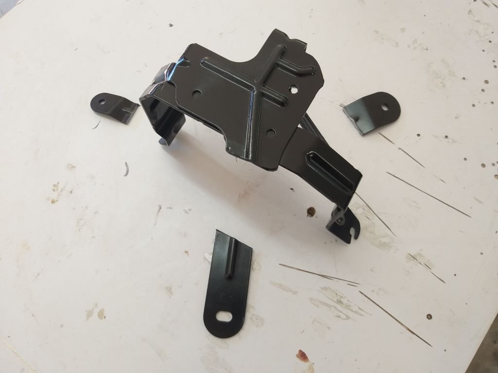
While the carby hat beautification project is steadily taking place in the background I thought I'd share the next item on the "to do" list with you. So, as I've mentioned before due to limited real estate in my engine box I'm only able to bless the mighty 3Y engine with one belt driven ancillary and at the moment that is the Mitsi Express belt driven power steering pump. However, the intention is to flick on our modern Bongo van and substitute the Thames as our everyday driver, and before this can happen, I need to fit a/c to the Thames. Now as I've mentioned before my initial plan was to run a 12-volt a/c compressor, but in talking to my local a/c guru I soon realised that whilst these little 21cc compressors work fine in compact hot rods they ain't going to cut the mustard in a relatively spacious Thames van. This leaves me with only one option being a beefy belt driven compressor, so the belt driven power steering pump needs to go. My first thought was to convert back to manual steering which I posted about a few weeks back and to be honest it absolutely sucked. I then turned to the OS tech forum for some guidance and those in the know suggested I look for a Holden Astra electric power steering pump as these would be relatively plentiful here in Straya. So, armed with a downloaded photo of an Astra TS which is the model required I headed over to my local wreckers. Turns out they had only one TS in stock and so I moseyed on over for a quick gander. The car looked absolutely mint. No accident damage and all that was missing was the front grill and exhaust manifold. Winner, I thought and proceeded to remove the pump which is a bitch of a job as those who have done this before will confirm. Anyway, the last step in the process was to cut the hydraulic lines and this is where things got interesting. Cutting into the pressure line resulted in not a drop of fluid leaking out. Hullo, I thought. Got it out into the sunlight and the reservoir was dry as a bone. Checked under the car and sure enough the steering rack and associated kit was still all intact. So how come this thing has no fluid I wondered. Anyway at $150 asking price and no guarantee as its classed as an electrical component I decided to walk away. Back at base camp I searched the web for another but prices for second hand units in the bigger towns over here run in the $200 plus figures. Eventually I decided to take the plunge on a new aftermarket unit which costs about double the going rate for a second hand one but comes with a 3-year replacement warranty. And then a few days later a friendly courier dropped this off: First thing I noticed was this funky looking electrical plug which I couldn't identify. I toyed with the idea of cutting off the plug, but the seller confirmed that this was likely to void the warranty. So I reached out to OS with a photo of the plug and luckily @tortron came to the rescue with a link to one which is now making its way from the other side of the world. While I'm waiting for the plug, I started poking around the van to figure out a suitable location for the pump. I was going to tuck it under the driver's side front fender, but the issue is access to the incorporated fluid reservoir for top ups, so I then focused on the back corner of the engine box where my existing Mitsi Express fluid reservoir is mounted. Pulled it out to clear some space and yep, this looks like it will work perfectly: Next step was to trim the redundant mounting tabs off the Astra mounting bracket: I'm just waiting for the touch up paint to dry and I can then puzzle out some kind of angled bracket to attach the Astra bracket to the rear wall of my engine box. Thanks for looking.
- 740 replies
-
- 13
-
-
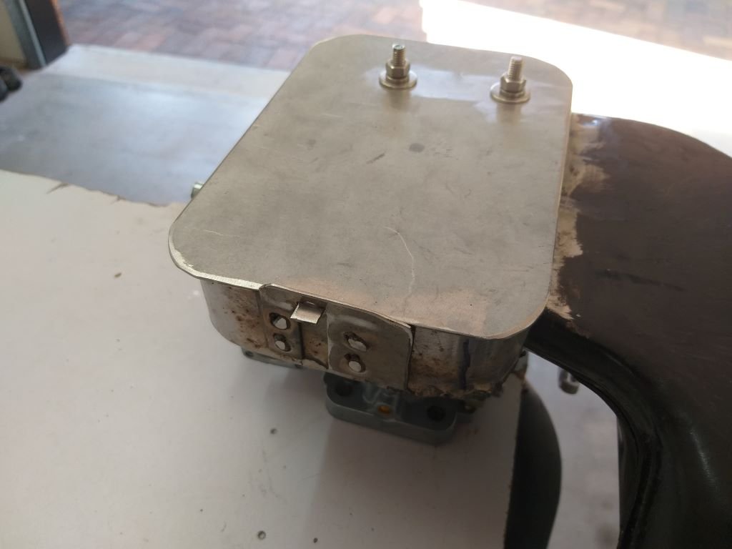
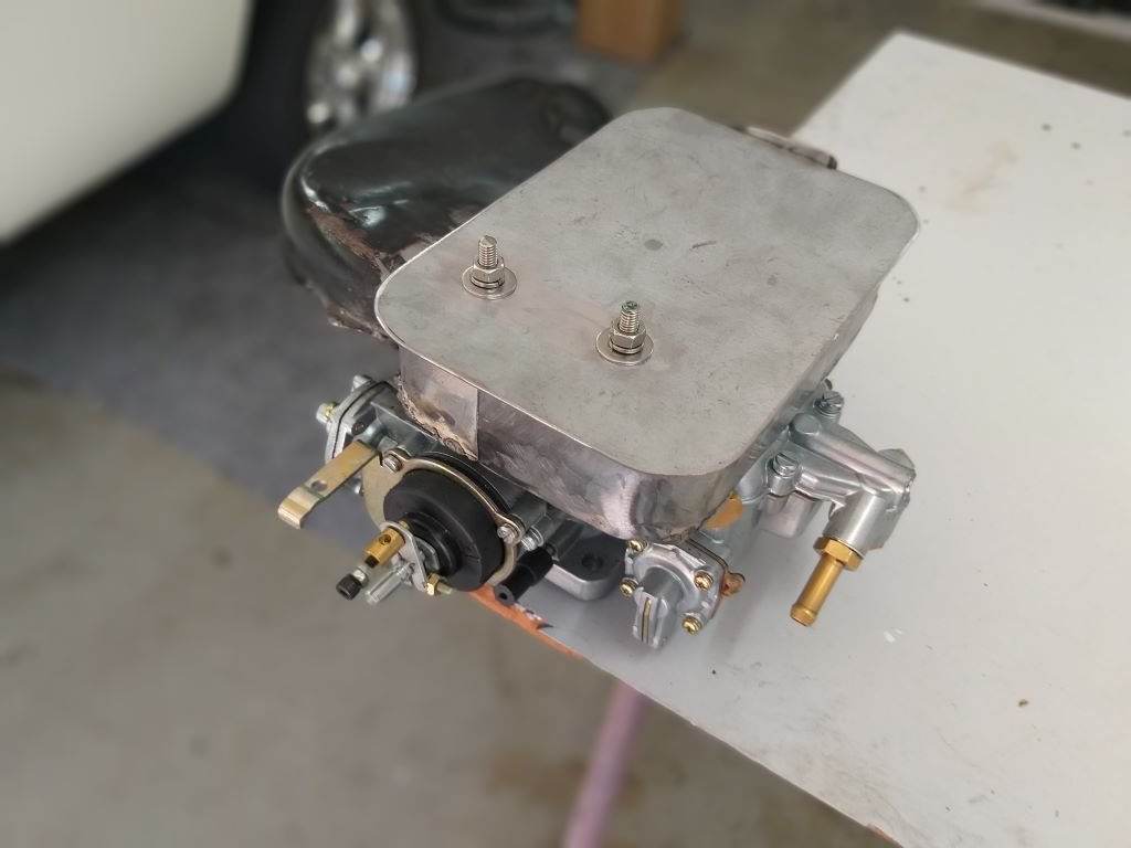
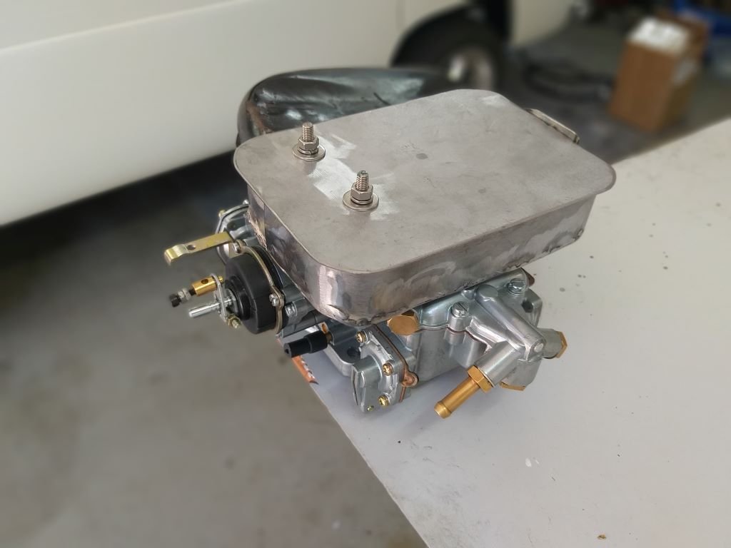
So, the plan with the new carby hat was to use the original chrome cover that came in the kit I bought. I was going to use 4 small sections of threaded rod screwed in to the carby flange that normally takes 4 short bolts to hold the filter base down. First step was to poke 4 holes in the lid and it all worked out okay on the test bench, but when I tried to fit it to the Thames ... instant fail. There just wasn't enough headroom to get the lip on the lid past the sides on my newly fabricated housing. Just shows you how space poor I am. I then thought about slicing off the lip on the short side in order to squeeze the top through the gap, but then realised that even if I did that there is no way that I was going to be able to get a hold down nut on the two threaded rods sitting under the floor. Bugger. After a bit of head scratching I came up with an alternate plan for the lid. First step was to carve a flat lid with a little tab out of some flat plate and I then carved up an offcut to make a little hold down bracket that I spot welded to the side of the base. Looks like so: The new lid slides between the sides of the base and the cab floor with about 7mm of gap. The two threaded rods closest to the rocker cover are well out of the way of the cab floor so I'm able to firmly bolt that end of the top down onto the rest of the housing. Not the prettiest looking thing but it is functional. Plan for tomorrow is to put a bit of lipstick on this pig, but for now here is a money shot of the thing actually in its final home:
- 740 replies
-
- 12
-
-
I've finally given up on my fibreglass carby hat. With the limited headroom that I have, I just couldn't get a low enough profile on my creation. Sad, I know, but such is life sometimes. Anyway, inspired by some photos that @yoeddynz shared of a carby hat that he fabricated for one of his customers, I thought I'd have a go at creating one out of metal. I followed Alex's recipe by slicing up the original HiAce hat. Since I'm not blessed with the carby headroom that a HiAce has I've had to create my hat in two sections that I'm able to slide in on either side of the choke tubes. Made some hoops out of flat plate which I then welded onto each half of a freshly fabricated base plate. Next step was to weld the remnants of the HiAce snorkle onto my creation. The HiAce steel is bloody thin and even with my cheapy welder on its lowest setting it was still blowing holes, so I had to resort to some dodgy spot welding. Not the prettiest thing you have ever seen, but it is strong and even if my flapper disk doesn't improve things I can live with it. At the end of the day most of it will remain hidden under the chrome top cover that I've pinched from the performance air filter. More planned for tomorrow, but in the meantime, here are a few photos for your viewing pleasure.
- 740 replies
-
- 11
-
-
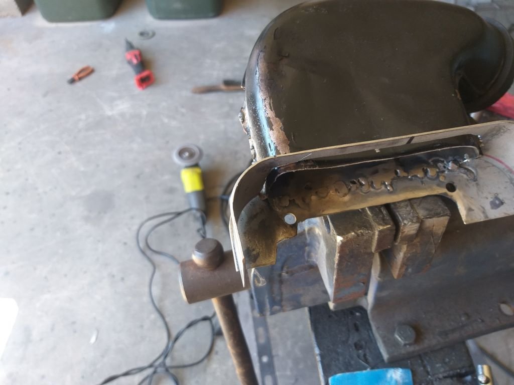
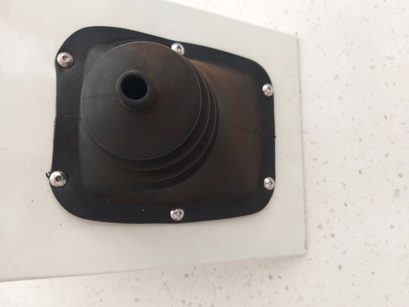
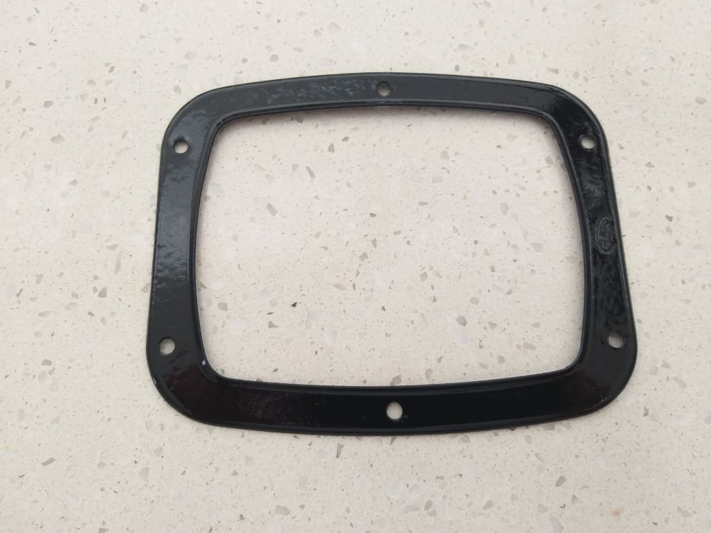
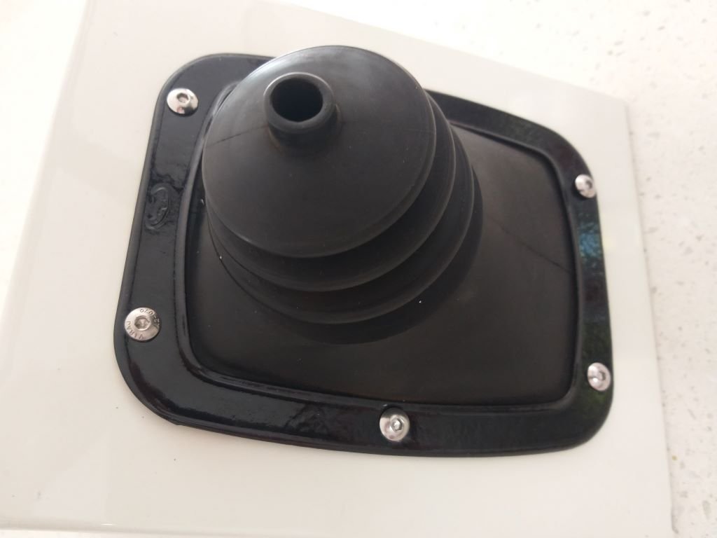
Having a bit of a cruisy day today. Earlier in the week I was giving my mate Grant a hand to fit a solar setup to his camper van and to say thanks he gave me a metal surround for the Cortina MK1 gearshift boot that he gifted me a while back. It was pretty crusty, but after spending three days in a vinegar bath it has come up pretty good. You can even make out the little "Enfo" factory stamp on the face. Gave it a spritz of satin black and then bolted it up. I'm bloody chuffed as it finishes the surround off nicely. I'm lucky to have such a generous mate.
- 740 replies
-
- 12
-
-
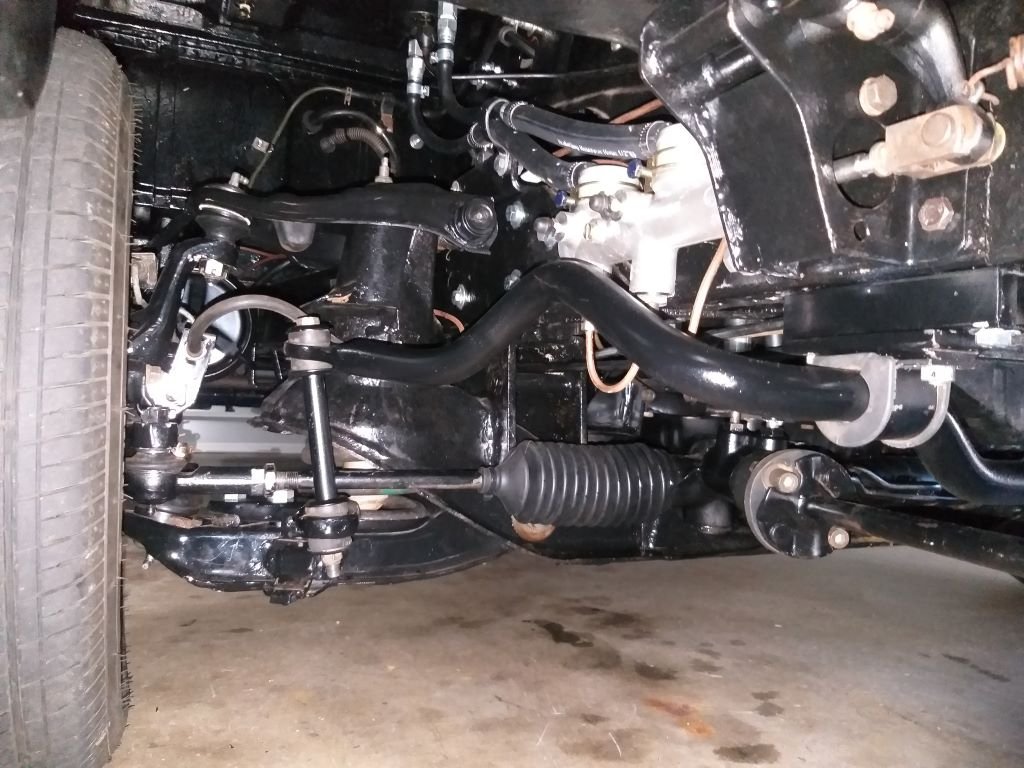
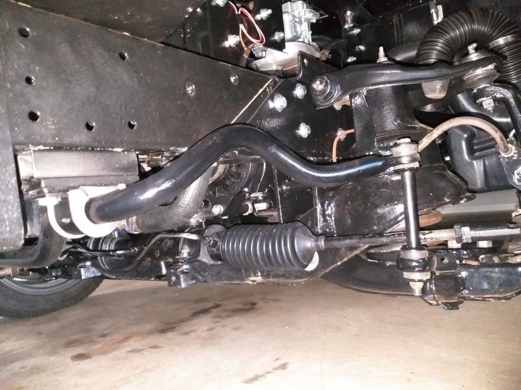
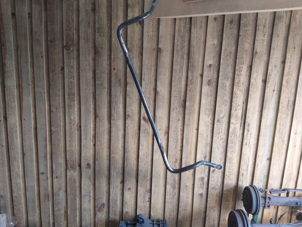
And this is hopefully the last time that I will mention the front stabiliser bar as by now I'm sure that you are as sick of the subject as I am ..... LOL. I'm looking forward to working on something else for a change.
- 740 replies
-
- 12
-
-
Front stabiliser bar - Chapter 11 Loaded Mrs Flash and our wee dog into the Thames for a blatt around our neighbourhood and I'm happy to declare that the excess body roll is now a thing of the past. Flushed with success I proceeded to dismantle the setup, then gave everything the once over with the wire wheel of death followed by a light tickle with a flapper disc. First coat of paint has been applied and I thought I'd post this update while I'm idling between coats. Just remembered I've got to sort out some crush tubes for the hollow square body mounts, so best I crack into that.