Flash
-
Posts
1615 -
Joined
-
Last visited
-
Days Won
2
Everything posted by Flash
-
Thanks for the feedback fellas. I really appreciate the pointers. I will double check things to make sure that the rack and the rack ends are the same level on both sides. Clint, in terms of the spindles and orientation of the steering arms I haven't changed anything. The L300 SD series front beam is setup as front steer from factory. All that I have done is replaced the SD series drag link steering with the rack and pinion from a newer generation L300. Thanks also for the suggestions on how to address the tie rod position. Being so "space poor" I reckon that would be the way to go rather than trying to raise the rack. Thanks again fellas. I'm kinda isolated out here and am so grateful that I have access to the wealth of knowledge that you and other old schoolers so generously share.
-
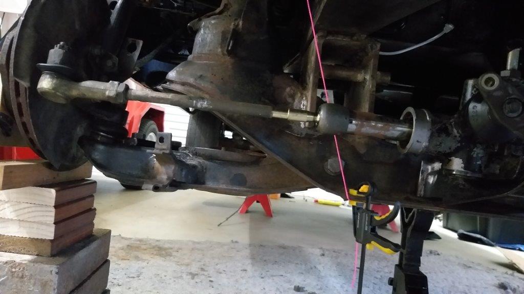
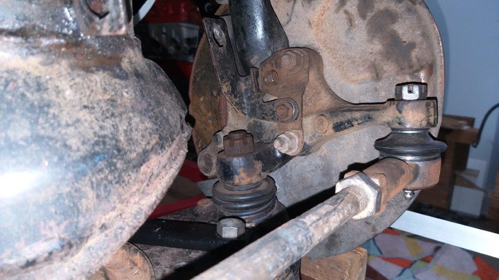
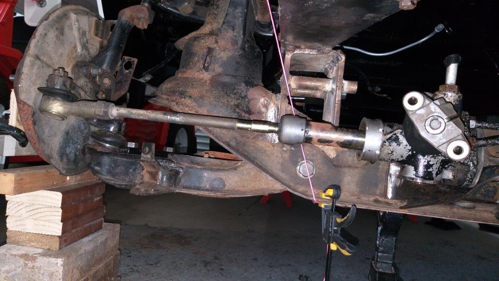
I've taken a few quick snaps for you Clint. These were taken with the suspension arms set at normal ride height. I really appreciate you taking a closer look for me. Shout if you need anything photo'ed in more detail.

-
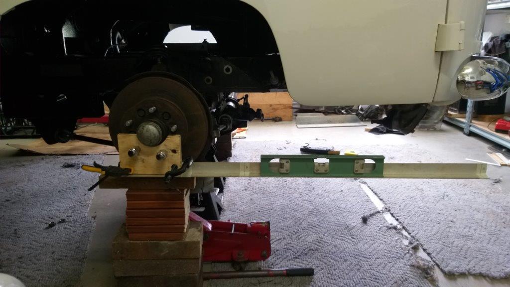
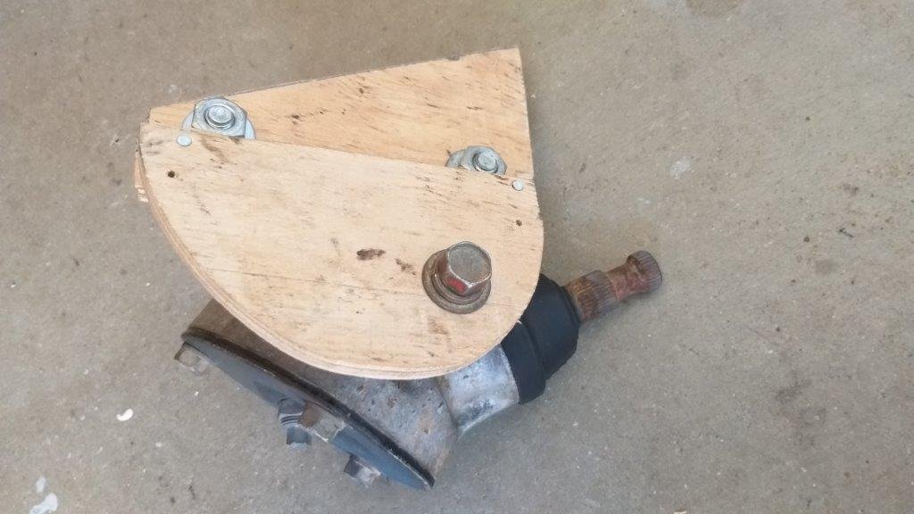
Well it's been another week of slow but steady progress on the old Thames. The first part of the week was spent cleaning, refurbishing, painting and then fitting more of the small bits and pieces. In between I've also been making a shopping list of additional nuts, bolts and washers that I need to pick up on my next trip to town. Towards the latter half of the week I thought I'd start finalising the steering setup as I still need to get the intermediate steering shaft that joins the rack to the steering angle box shortened to the correct length. However, the dilemma is that I can't work out the final length of this shaft until I am 100% happy that the steering rack is mounted in the correct place. The rack mounting bracket is currently tech screwed to the L300 front beam and I don't want to weld it up until I've confirmed that the position is correct. In it's current position the rack end pivot points form a nice straight line with the upper and lower suspension arm pivot points, so I know that I am more or less in the ballpark, but the unknown at this point was whether I'm going to experience any bump steer issues. I'm the first to admit that I'm a little ignorant when it comes to bump steer so I popped up a query on the tech forum asking for some guidance and I'd like to thank @cletus, @adoom and @thepog for their input. @cletus kindly provide me with copies of the LVVTA bump steer doccos which provide some valuable info and at the same time he and @adoom encouraged me to build my own bump steer tester. I've now tested for bump steer and can confirm that I am experiencing 1.6 degrees of toe in under maximum suspension compression and 2.0 degrees of toe out under maximum suspension droop. The LVVTA docco suggests that my tie rod is currently sitting too high and @cletus and @adoom have confirmed that I need to raise the rack a bit. I've currently got the engine and gearbox out, but from memory I've only got about 10mm of space between the top of the rack housing and my harmonic balancer and I don't think I can raise the engine any higher without causing clearance issues between the top of my carby hat and the underside of the cab floor. Despite this challenge I'm pretty chuffed with the results as I could have been facing rack length issues which would have been a lot harder to address. I'm thinking I need to get the engine and gearbox back in and then see if I can squeeze a bit more space to raise the rack. Pic of one side of my rudimentary bump steer test setup at maximum compression included below. The measuring tool on the other side looks the same. Thanks for reading.
-
Thanks for the advice @cletus and @adoom I really appreciate your guidance. Yikes, I was hoping you weren't going to say that I need to lift the rack. I've got the engine out at the moment but from memory I've only got about 10 mm clearance between the top of the rack housing and my harmonic balancer and I can't raise the engine anymore without causing clearance issues between the top of the carby and the underside of my cab floor. I'm thinking I should get the engine and gearbox back in and then see if I can tweak things a bit more.
-
After reading through the info sheets provided by @cletus and spurred on by his encouragement I spent a bit of time yesterday building a rudimentary replica of the LVVTA bump steer test kit. After setting my caster and camber this morning I cracked into some bump steer measurements. The results indicate that I am getting a maximum of 1.6 degrees of toe in under full compression and 2.0 degrees of toe out under maximum droop. Based on these results the LVVTA notes say that my tie rod is too high. I'm clueless as to how I can fix this, so would appreciate some guidance from those in the know. Ta in advance.
-
Thanks very much for the additional reading material and detail @cletus. Thanks also to @adoom for the pic of your test setup. @ThePoghas also made some good points. Thanks fellas, I really appreciate the info and advice.
-
I'm in need of a bit of advice from those who know a lot more about bump steer than I do. Visually the pivot points on my steering rack ends form a straight line between the pivot points on both my upper and lower suspension arms, so I know that I am somewhere in the ball park, but decided to seek a bit more confirmation by actually putting the suspension through its paces. So in the absence of any specialist tools I've completed the following rudimentary test: With my steering rack and all other front suspension components except for my shocks and springs in place, I have used a trolley jack under the lower suspension arm to raise the suspension from maximum droop to maximum compression. I did this test in turn on both the left and right hand sides, but not simultaneously. During each cycle on both sides I closely watched the steering shaft input spline (I don't currently have the steering column attached to the rack) and in all instances the input spline did not budge at all. Since I have already confirmed that there is no play in the steering rack itself, is it safe for me to assume that I am relatively in the clear from a bump steer point of view ? Please feel free to shoot my simple theory down in flames .... I promise I wont be offended.
-
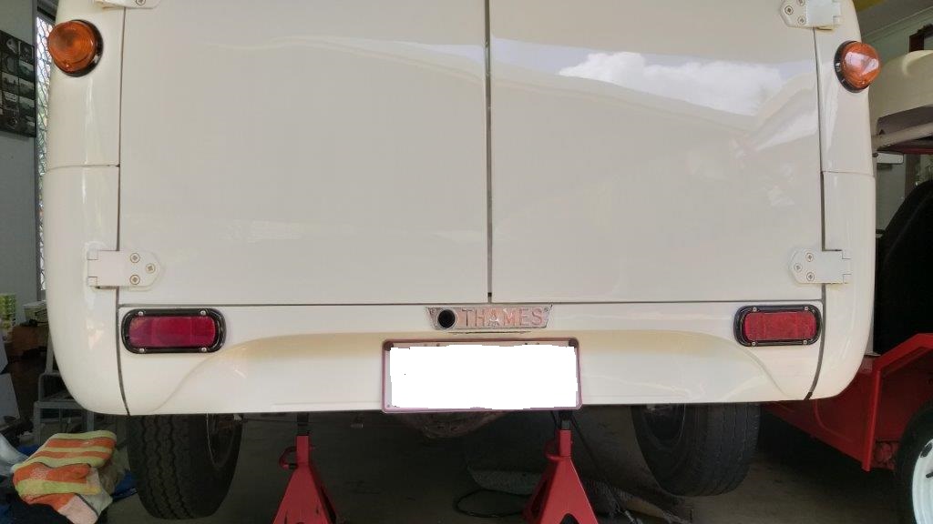
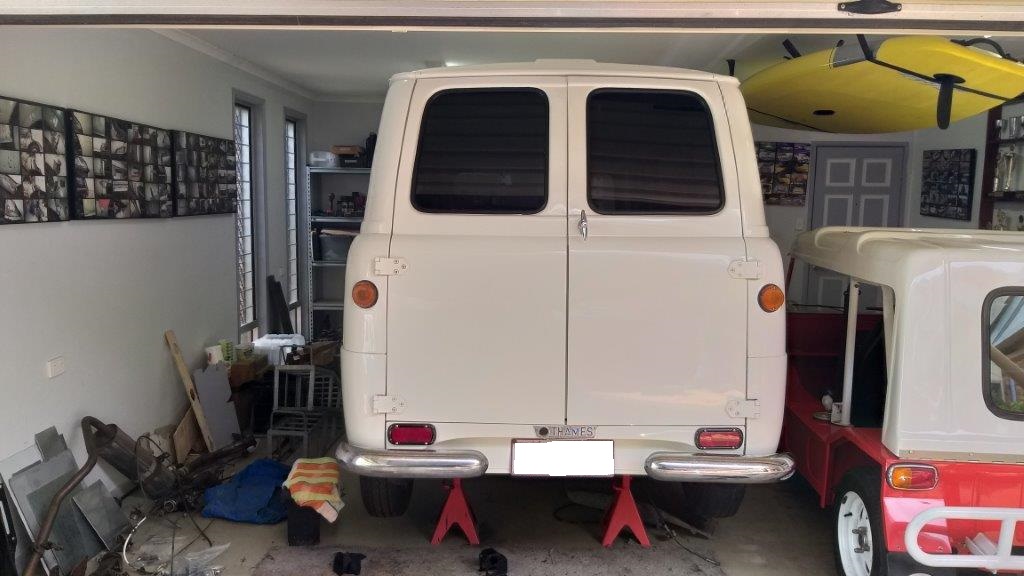
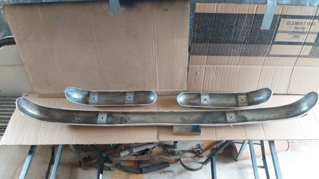
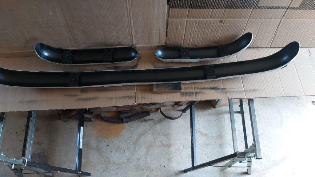
I got tired of tripping over the back bumpers so thought I'd fit them. First time that they have been on the van during my ownership so it's going to take a bit of time to get used to the different look.
-
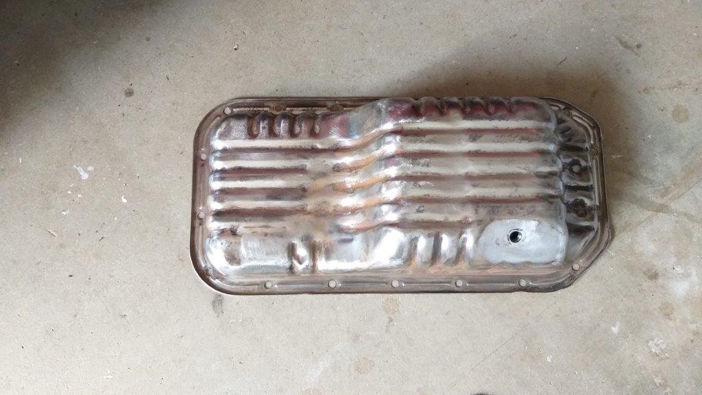
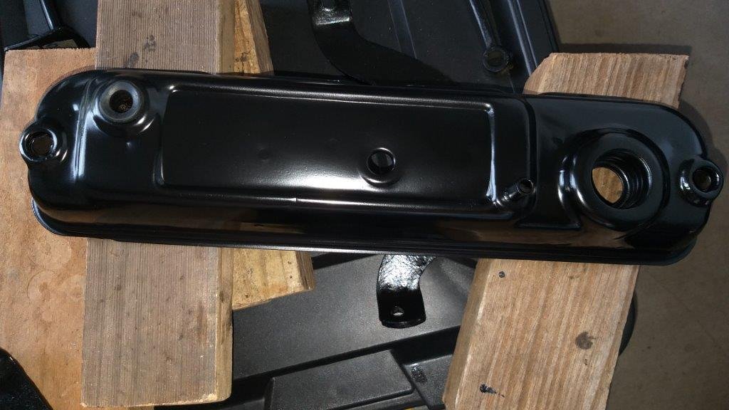
Today I made a start on tidying up some of the loose engine parts. De-greased the tappet cover and sump and then took to them with a wire wheel. Chucked a few coats of satin black engine enamel on the tappet cover and it came up mint. The indentations on the sump need a bit more work before its ready for paint so I'll carry on with that tomorrow.
-
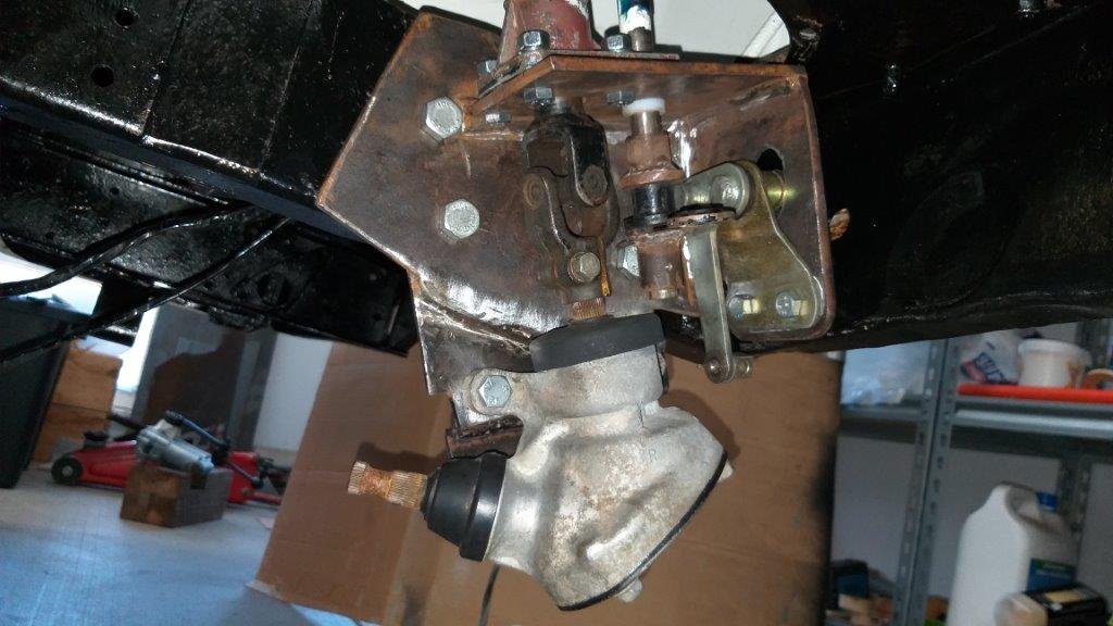
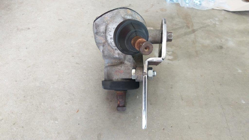
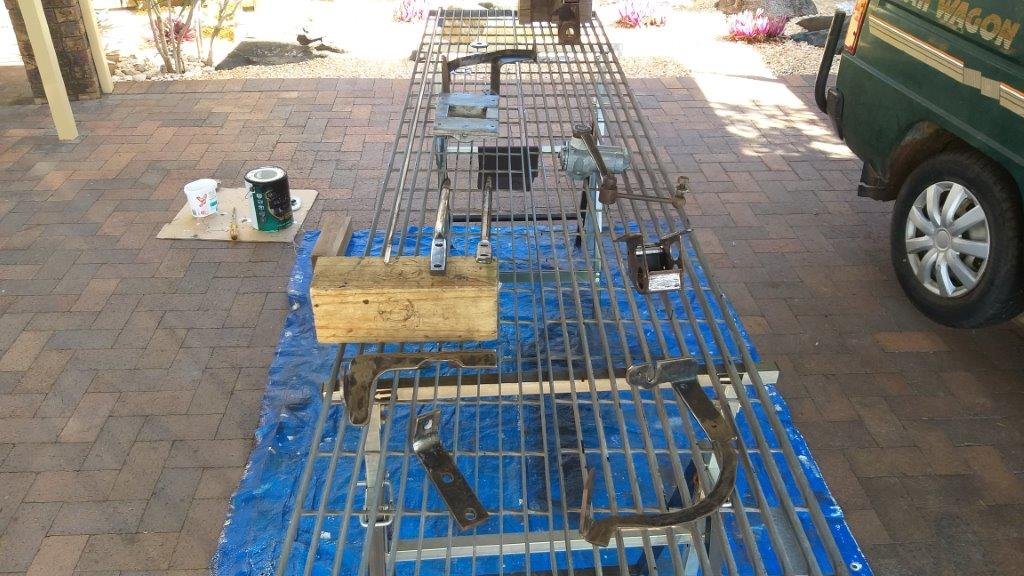
Happy New Year ! Thought I'd start 2021 off by test fitting my combined steering bracket, so chucked it on with a few random nuts and bolts. Although the rack isn't connected up yet, the movement of the steering shaft and angle box is nice and smooth. Whilst putting the gearshift pivot arm through its paces I noticed that the shift cable rubs up against the chassis leg at full arc. Not ideal, so I decided to do something about that. Pulled everything apart again and have now re-positioned the mounting holes for the arm slightly lower. Meant I needed to elongate the hole in the bracket that the pivot pokes through. The elongated hole doesn't look that pretty, but it does the job. Fitted everything up again and the cable now has plenty of clearance. The steering bracket with all of its attachments looks like a busy little office, but there is space between the various components so hopefully it will all work out okay. Thanks for looking.
-
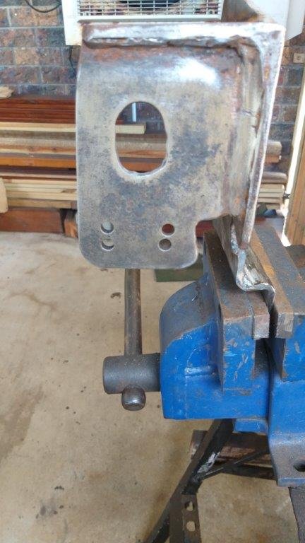
Heavy rain stopped play yesterday, so I only got to glue the steering bracket together today. Just needs a final tidy up with a flapper disk before I call it done.
-
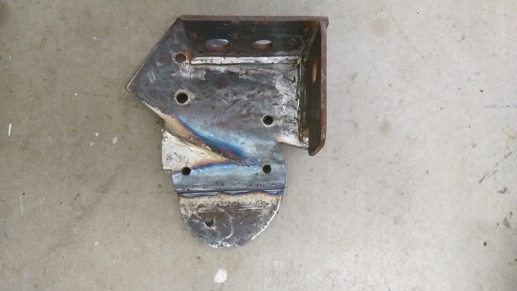
And another pic with the angle box attached.
-
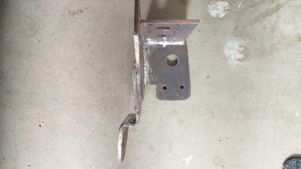
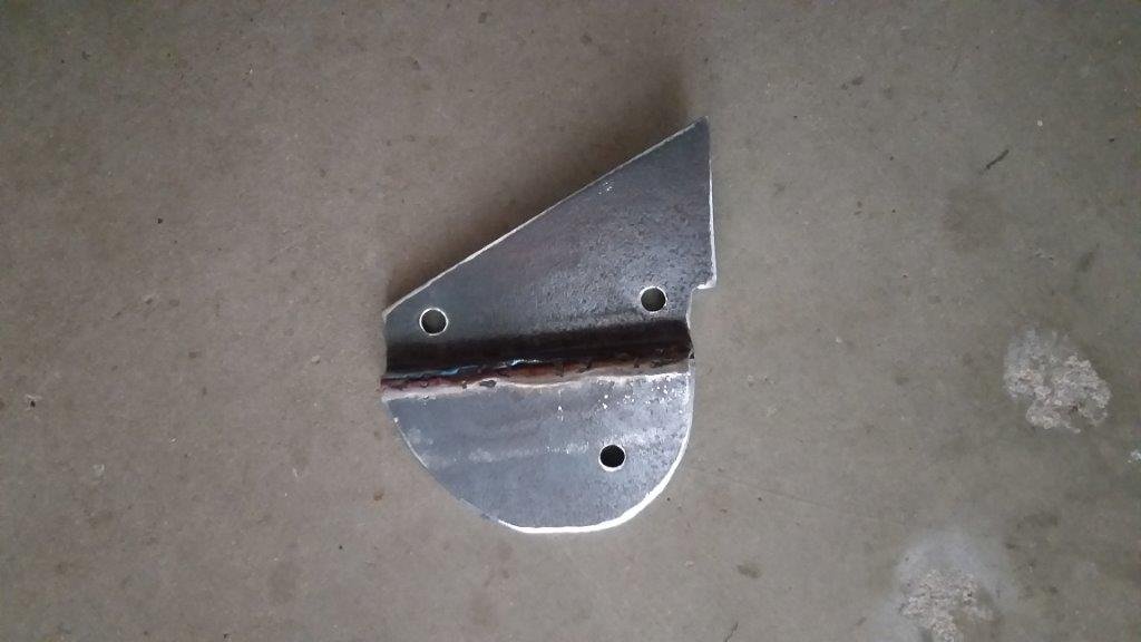
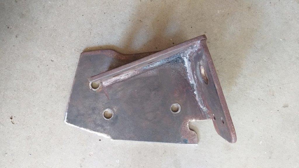
And that's the bottom portion of the steering bracket carved out of 6 mm plate. It took a few goes before I got the offset perfect. Next step is to glue it to the main bracket and then do a final tidy up of the welds.
-
Brilliant colour choice Conrad ! I can't wait to see it all assembled again.
-
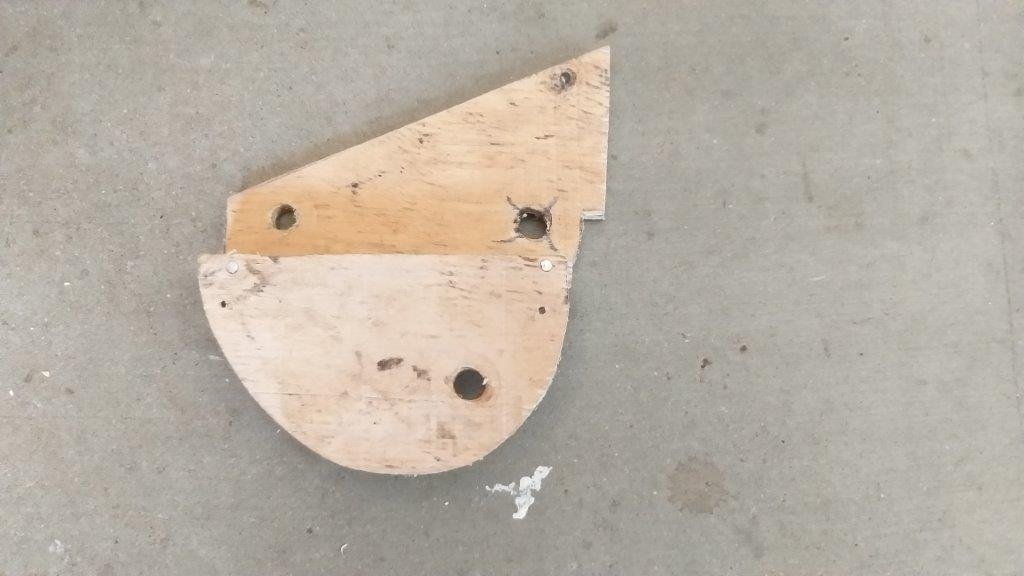
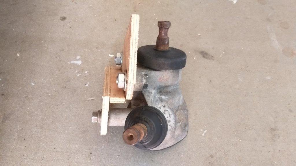
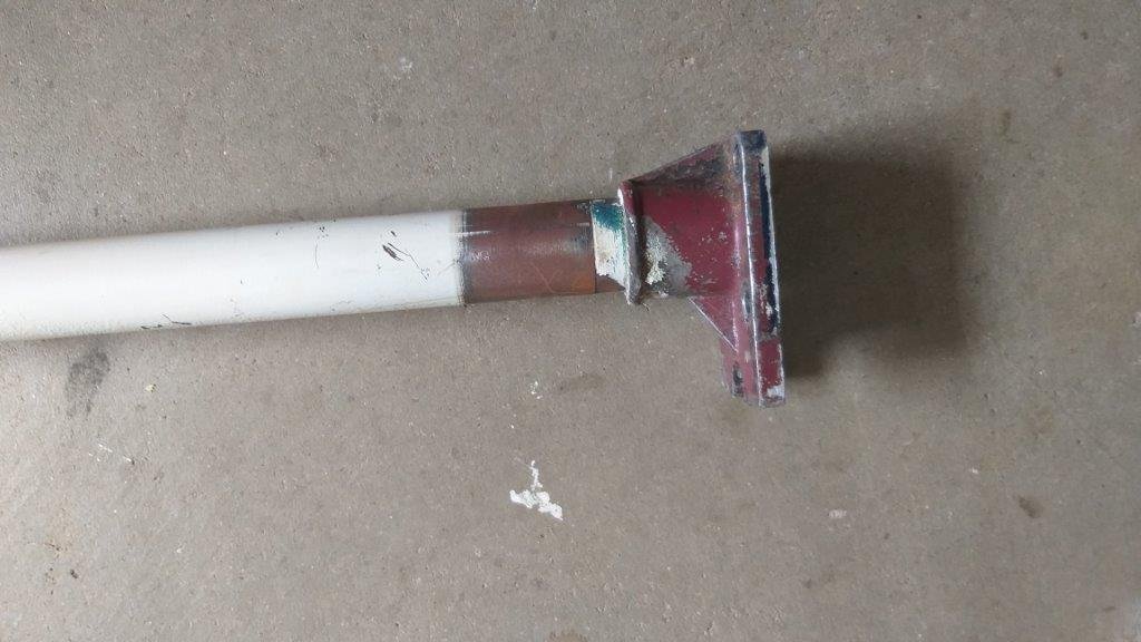
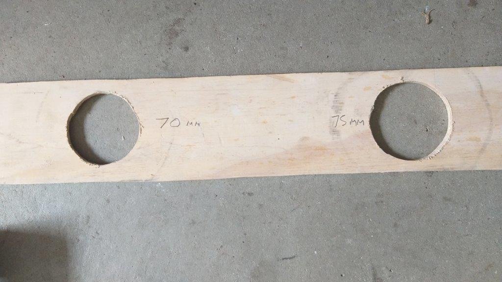
I had mixed success at the rubber place in town yesterday. Managed to get a pinch weld style rubber for my front doors so I was chuffed about that. Sadly they didn't have anything near as large as the 70mm rubber grommet that I need for my steering column. Hopped on fleabay when I got home and the only listing I could find for a 70 mm OD grommet was a crowd in China so I've resorted to ordering a few in. Thanks to Covid estimated delivery date is early March so I'll fabricate the plate in the mean time and will fit the grommet once it arrives. This morning I thought I'd make a start on the second portion of the steering bracket which is the part that the L300 angled steering box mounts up to. Did a bit of plywood aided design and successfully managed a test fit. With the Thames steering column mounted in its final position the L300 UJ that I had welded onto my Thames steering column runs nice and true. Tomorrow I'll replicate the plywood mock up in 6 mm steel plate and will then glue it to the existing part. Thanks for looking.
-
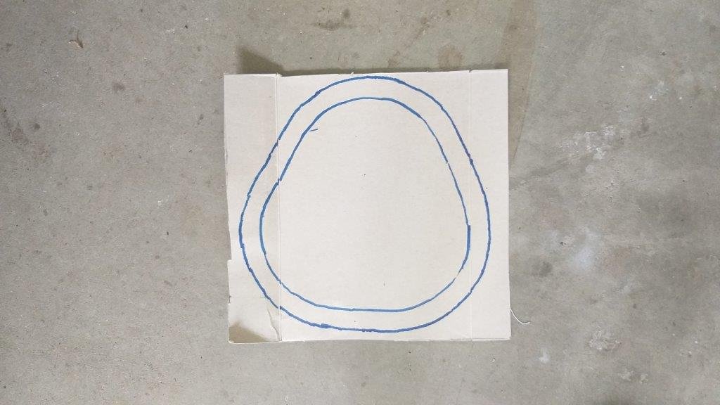
Merry Chrissy All from the team of one at Rough & Ready Restos. It being a special day I thought I'd treat myself to something other than cleaning crusty old Thames parts. Figured now would be as good a time as any to work out how I'm going to fabricate the floor plate that surrounds the steering and gear shift columns. My initial thinking is a solid plate with two holes cut out - one for the steering column and one for the gearshift column and then some rubber grommets to give me a weather seal. Started off with some basic cereal box aided design to get the rough shape of the plate. Next step was to figure out how big a hole I need in the plate to get the steering column foot through so cut a few rough holes in a bit of plywood. The magic number is 70 mm. The gearshift column is easier as it is just a straight rod. There isn't much room between the two columns so the outer grommet diameters will need to accommodate for that. My local rubber shop is having a Boxing Day sale tomorrow so I'll head along to get some pinch weld for my front doors and hopefully a few rubber grommets at the same time. Thanks for looking
-
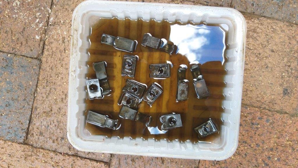
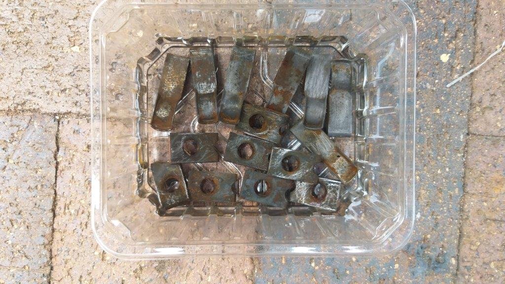
Well, not really, it's just the result of some small crusty looking clips that sat in a vinegar bath for a few days. Gave them a quick once over with a Stanley blade to get off the stubborn bits, soaked them in a bit of fuel, then back into the vinegar bath for round number two. Onwards and upwards. Thanks for looking.
- 715 replies
-
- 11
-

-
Then I cooked up a little something:
-
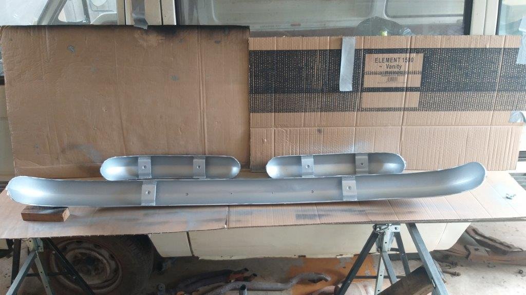
I'm still donkey deep in cleaning and painting all of the smaller parts before final assembly. After spending a bit of time sanding down the backs of the bumpers I declared them as good as I was going to get them. Chucked on a few coats of combination rust converter / primer followed by top coats of galv paint and I'll call them done. Hopefully that should protect them for a few more years.
- 715 replies
-
- 11
-
-
Spent yesterday preparing the second batch of parts for paint. A few needed some welding touch ups whilst others just needed a good de greasing followed by tickle with a flapper disc and a bit of wire wheeling. It's relatively mindless work, but needs to be done. Managed to get a first coat on them this morning. While they were drying I cut some extra thread into the rear axle U bolts necessitated by the removal of the two lower leaf springs. So that's another small job ticked off the list.
-
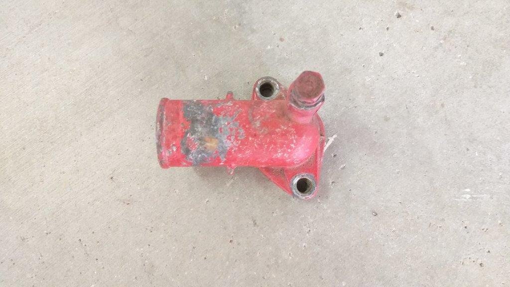
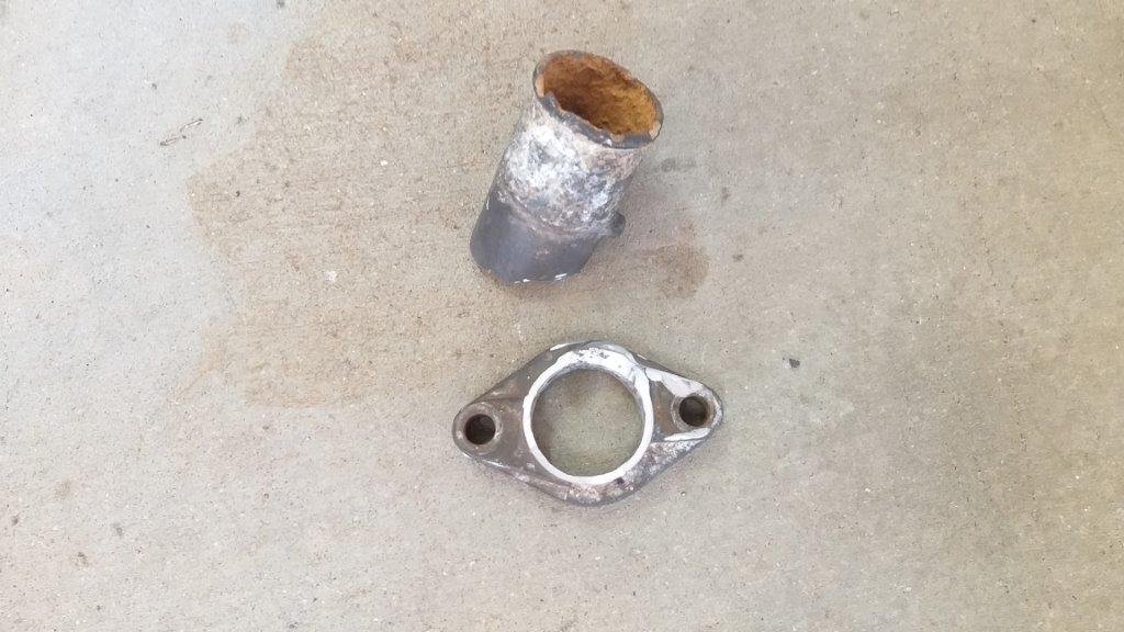
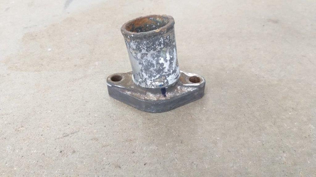
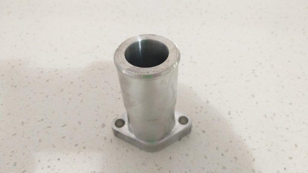
Those of you following my progress will recall that a while back I had cut and re-orientated the water neck on the 3Y to suit the Thames radiator and just needed to get it glued together. (pics below as a reminder) Anyway, a few weeks back I took it along to Brenton as his team does aluminium welding. The original neck was already showing signs of pitting and after a bit of a yarn with Brenton we agreed it would be far better if he carved me a new neck out of aluminium. At the same time I asked him to carve a reducer to connect the different diameter lower hoses together. Just after smoko today I got the call to say the bits were ready for collection, so I shot through and picked them up. They have come up really mint and the new water neck enables me to use a single 45 mm diameter hose rather than the original two hose setup I mocked up, so much easier on the eye. Thanks for looking.
-
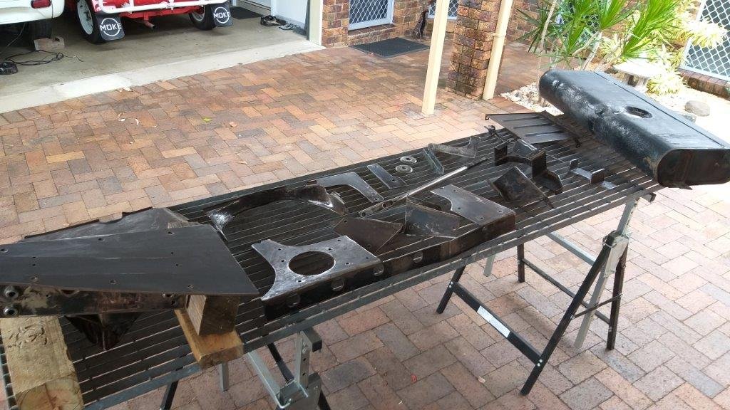
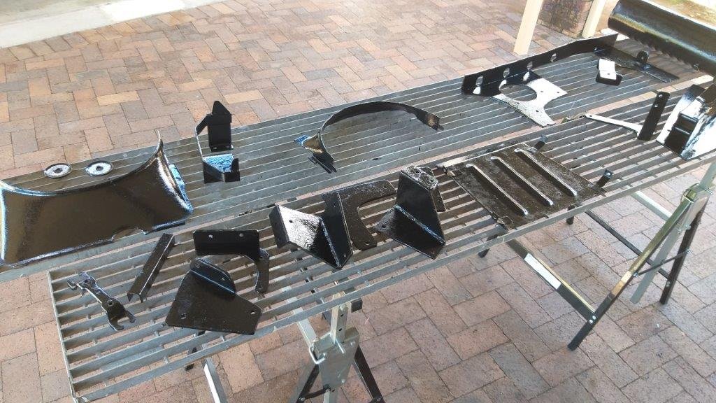
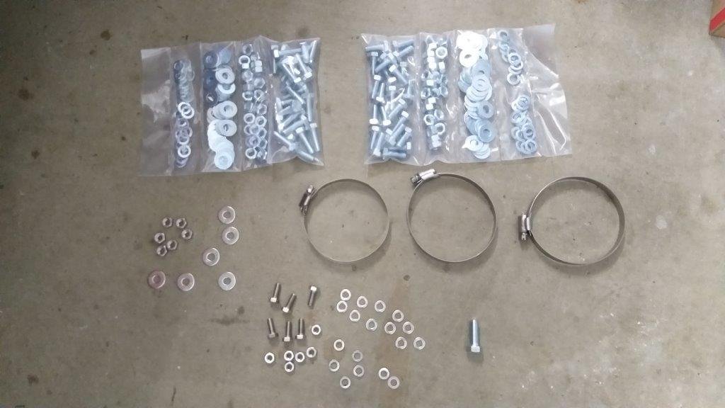
I've been quietly plugging away at a few things over the past week. Managed to paint the first batch of previously fabricated brackets and mounts and grabbed some new fasteners whilst I was in town yesterday, so I can start the re-assembly. The textured paint that I am using throws some ugly looking shadows, so you'll just have to take my word for it that they look much better in real life.
-
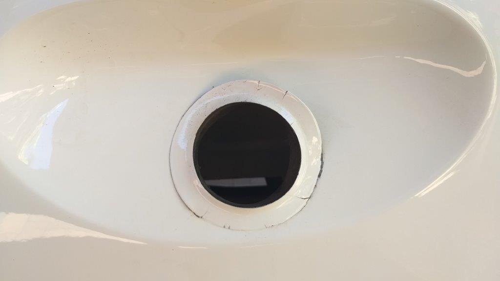
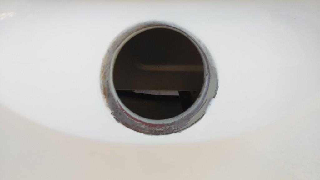
Talking about fuel tanks, what kind of muppet does a bare metal restoration and leaves the old rubber fuel neck grommet in place ? Hard to believe It was done by a professional restoration company. If I had been the one who paid for the job I would have been spewing. I carefully cut around the paint and was able to remove the grommet with no further damage. The grommet is shared with an Anglia 100E saloon and the good news is that reproduction ones are readily available in the UK. Further good news is that they have a larger outer diameter, so with a bit of luck the new one should totally hide the old paint. Thanks for reading.
-
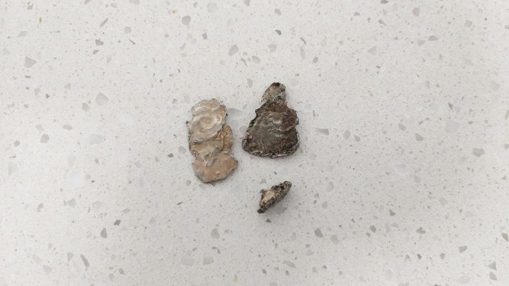
Grabbed the tank to give it a final once over before paint. Pulled the sender unit and the gasket is toast so I'll make up a new one before refitting. Tank still looks pretty clean inside, but I could hear something rolling around. Spent a bit of time jiggling the tank back and forth to work the bits through the gaps in the internal baffle plates and eventually managed to retrieve some decent chunks of old solder. All quiet now, so that must be the lot. I wonder how long those have been in there.
-
Then tackled one of the rear shock boxes. Looked like grease at first but turned out to be stuck on real good, so I'm thinking maybe road tar. Anyway lots of wire brushing and liberal applications of petrol and I eventually got it clean enough to make out the manufacturer's name in the casting. Made by Armstrong interestingly enough. One down, one to go.