Flash
-
Posts
1,719 -
Joined
-
Last visited
-
Days Won
2
Content Type
Forums
Downloads
Events
Gallery
Everything posted by Flash
-
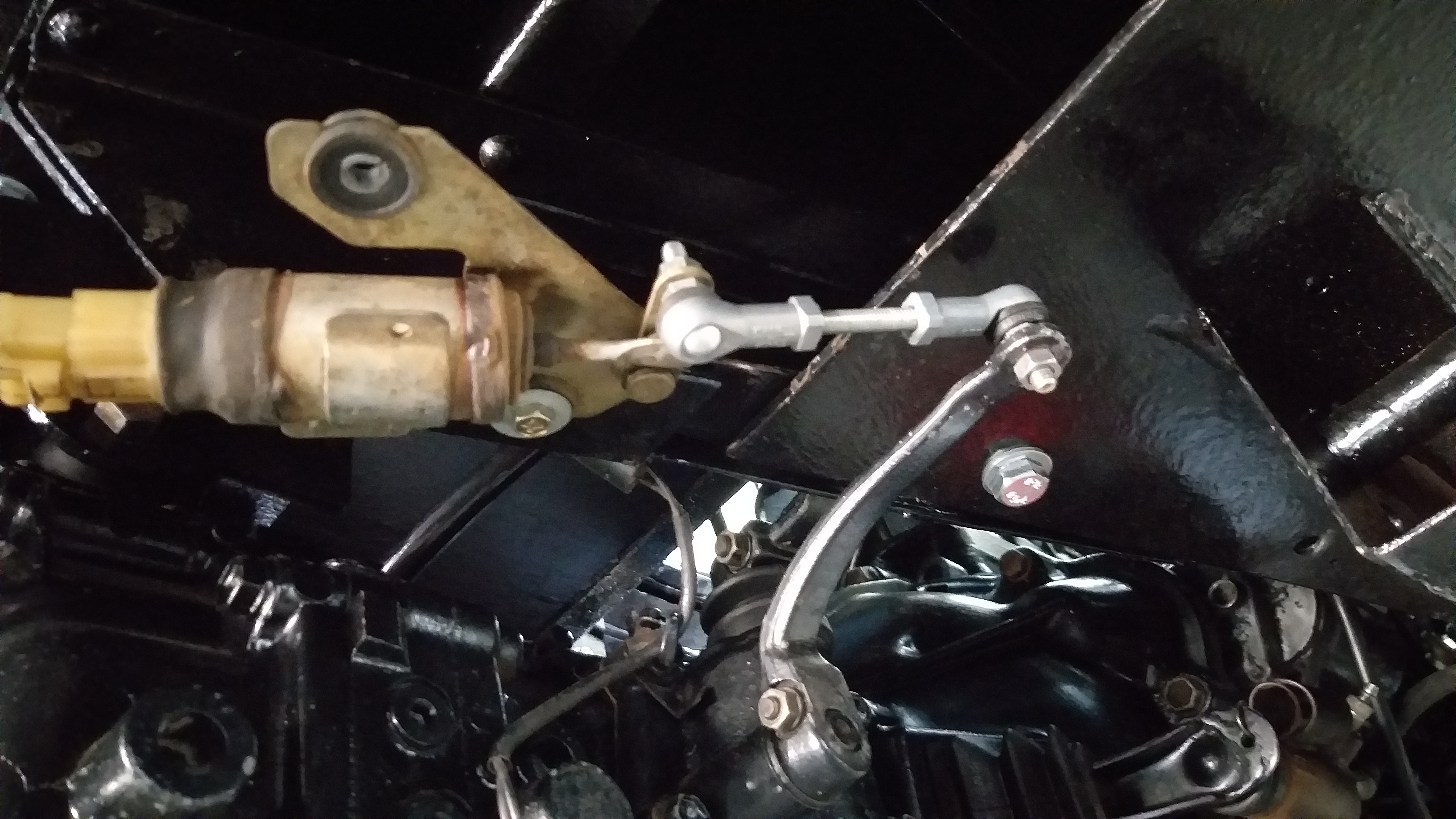
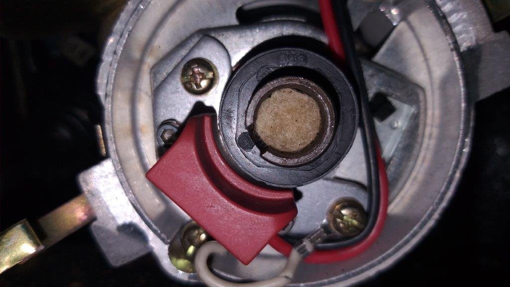
Hiya Bryan, I've got no idea what unit it is. Does this photo provide a clue ?

-
Thanks for the reply Tory. you raise a good point regarding the coil. Its a standard Bosch GT40 with no ballast resistor. It was the original that I was running when I had points. So maybe it's not the correct coil to be using with the electronic unit.
-
On simulated cranking (ie ignition key turned fully, but exciter wire for starter disconnected) the voltage reading on the coil wire measures 13.56 volts. This compared to 13.8 volts across the battery terminals before running the test. The coil is a red Bosch GT40 with no ballast resistor.
-
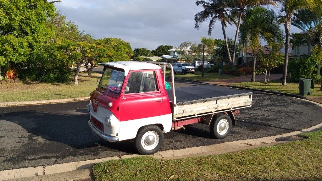
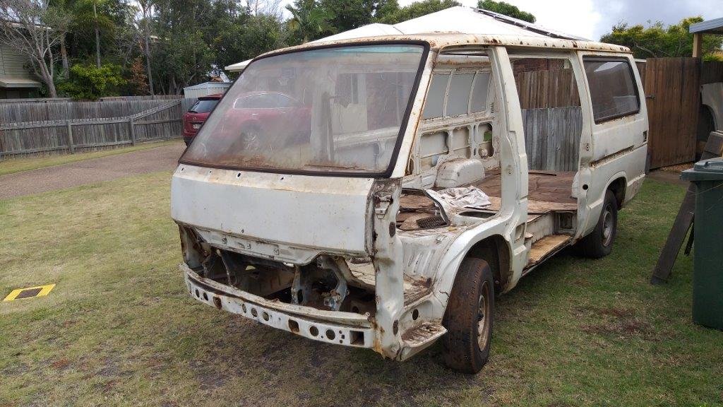
I'm in need of some guidance from the Leyland A series experts out there in old school land. Our Moke is running a 45D distributor that has been converted with a little electronic unit rather than the usual points setup. I've recently started experiencing a spark related issue on initial startup from cold after the Moke has stood idle for a few days. Some diagnosis on my part has revealed that when cranking the cold engine I get no spark at the plugs until I back off the ignition key at which point I get a momentary spark. Checking the voltage at the coil positive terminal during these conditions confirms a voltage of 9.2 volts whilst the starter is cranking with no spark at the plugs. If I check the voltage on the same wire with the ignition key engaged but the starter motor disconnected I get 12.6 volts. My first question to those in the know is whether a voltage drop from 12.6 volts down to 9.2 volts during cranking seems like an excessive drop ? Then if I charge the battery up overnight and again check the voltage on the coil wire during cranking I get 9.74 volts and consistent sparks at the plugs. My second question is does it seem reasonable that the slight increase of 0.5 volts should be sufficient to enable the coil and distributor to do their job correctly? Then in terms of finding a permanent solution to the issue : 1. Could my starter motor be on its way out thus resulting in the large voltage drop during cranking ? 2. Could my battery be on its way out thus resulting in a drop in available voltage when not boosted by an overnight trickle charge ? 3. Could there be something else causing the issue ? Any help would be greatly appreciated. Photo of offending vehicle, just cause I know you all like pics. Ta in advance.
-
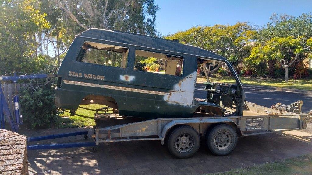
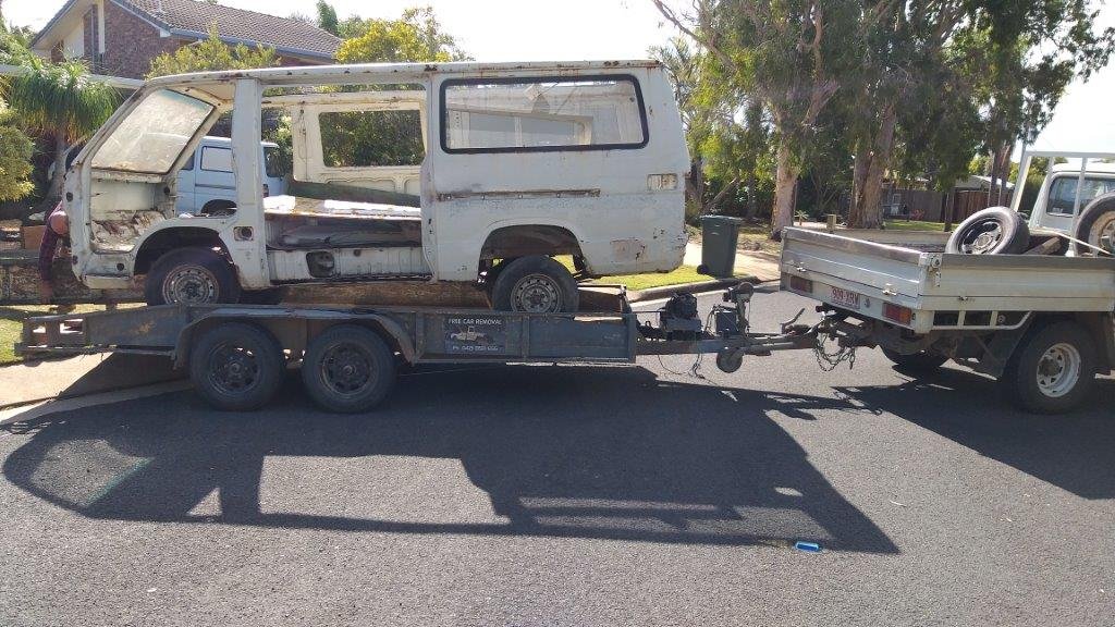
And another one heads off to be reincarnated as a toaster.
-
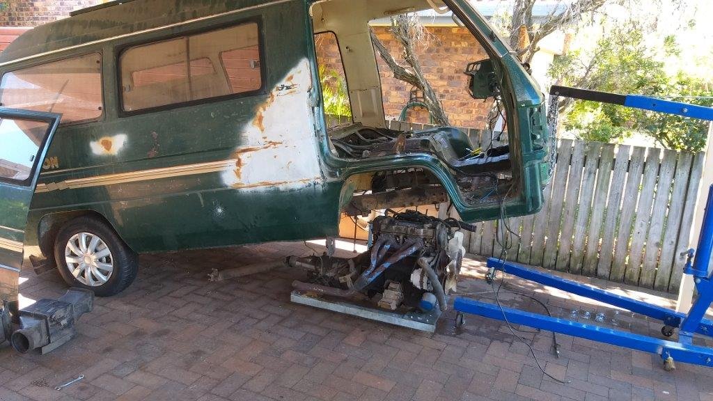
More progress today. Managed to remove the engine and gearbox from the donor Starwagon. I decided to lift the van rather than drop the engine and box as I had visions of another crushed hand, but all went well this time. Pic or it didn't happen.
-
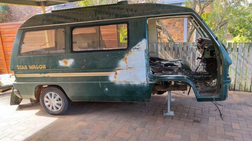
This morning I thought I'd try to get back on the tools. I managed to ease a work glove onto my damaged hand to offer it some protection and then made a start on pulling my donor Starwagon apart. The hand held up surprisingly well so with a bit of luck I should get the engine and gearbox out tomorrow.
-
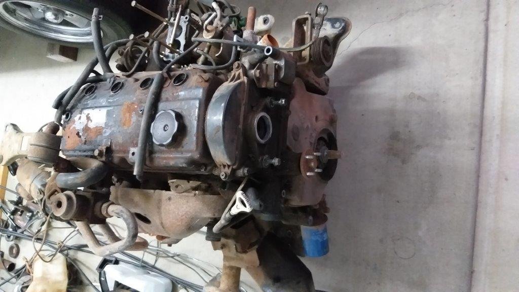
Yikes, you know that things have slowed down when you have to scroll to page 3 to find your build thread. Having said this I've got a pretty good excuse. So, the day after my last update I got a call from someone who was interested in the gearbox out of my Express donor van. He was in a hurry for it so I quickly dropped the engine and gearbox and was busy separating the two when the engine toppled over and crushed the small finger on my right hand. It's my own bloody stupidity as I was in a rush and had taken a short cut. Needless to say it has been a tough month and a bit. At one point the finger looked to be in jeopardy, but thankfully things improved. The splint came off last week and although I still have no feeling in the lower part of the finger I have regained some movement in the middle joint, so hopefully I'm over the worst. In case you are busy eating breakfast, lunch or dinner whilst reading this I won't post any pictures of the finger, but here is a pic of the offending engine which I haven't even had the stomach to look at since the dastardly deed took place. Anyway, onward and upward as they say.
-
Good score Conrad !. Can't wait to see what you do with this one.
-
And then in other news a fellow Thames enthusiast who is visiting the area dropped by for a yarn. This sweet little truck is fitted with a V8 and associated running gear out of a Leyland P76. The cab has been converted to tilt for full engine access.
- 740 replies
-
- 17
-

-
So two things happened today. My mate Trevor dropped by to pickup the remains of donor HiAce 2. I pulled the HiAce back axle out and slung and old Thames unit under there just so we could load it up. Goodbye old friend.
-
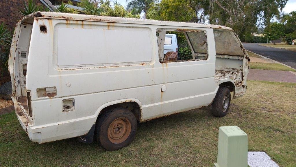
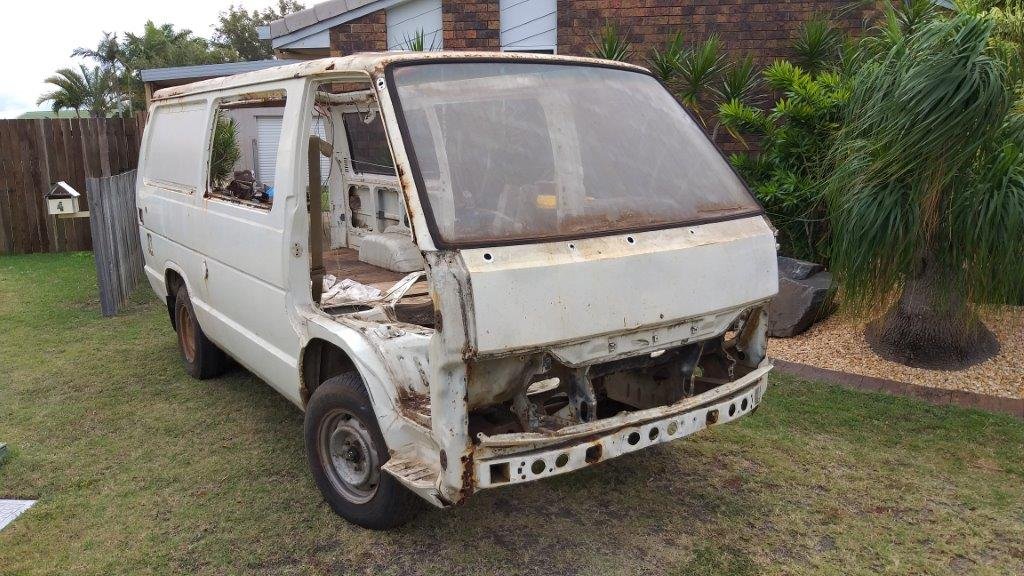
Long time no update, but that doesn't mean that nothing has been happening. I've spent hours and hours trying various things to get my gear shift to the point where I am 100% happy. I've shelved the option of using electronic solenoids for now as it would just add an additional layer of complexity. I'm seriously contemplating changing over to a 4 speed auto if I can track one down. Just so that I can keep the interior looking stock with the column shifter. The same model HiAces that I got my engine from were equipped with a A44DL auto, but they are pretty thin on the ground over here in Straya. I go all excited the other day as our local wrecker got in an auto Townace, so I raced around for a look see. Unfortunately it is the newer generation A46DE which would again just complicate things. In other news, late last week I decided to take a break from the Thames, so cracked into stripping down my second donor HiAce. I've harvested just about everything of value. The back axle still needs to come off, but I'll do that once its on the rollback when the scrappy comes to fetch it next week.
-
Thanks fellas, I appreciate the additional guidance. I'll do some more reading.
-
Thanks fellas, I really appreciate the additional info. Yep, @spencer, first prize would be a top hung A44DL as that would bolt straight up to my 3Y engine. I'm up Bundy way and have got a wanted add up on Gumtree at the moment, but like you say the older boxes are pretty thin on the ground these days. This A46DE that I found is out of a '96 Townace. Being top hung as well as being bolted up to a 4Ye engine, it would be a breeze to fit physically, but playing around with shift controllers and other modern lectrics is way beyond my skills base. @cletus, your comments on being able to rig up some power to "manualise" the gear changes got me excited as I hadn't thought of that. My Thames van project has stalled a bit at the moment as I'm really struggling to get the original column shift to precisely shift my Toyota G54 manual box and I really don't want to fit a floor shift. I'm going to give some more thought as to how I could potentially get the shift solenoids to fire correctly through some form of electrical switching coupled to the column shifter. Thanks again for the input gents. Chur.
-
Did a bit more digging around this morning and it looks like the DE version is equipped with three solenoids that are controlled by the Power-train Control Module. Two of the solenoids control the shifting and the third controls the torque converter lockup. So by the sound of things there is no way for me to get the shifting to work without the electronics. Bugger !
-
I'm in need of some more help from the Toyota experts : So from what I have read on The Google the successor of the A44DL auto gearbox is the A46DE which apparently is blessed with some form of electronic control. Can anyone confirm exactly what is electronically controlled in this box and whether there is any way to bypass or jury rig the electronic bits. Any advice or further info would be greatly appreciated. Ta in advance.
-
And here is a link to a longer version of my test. https://youtu.be/5FQ_NSinxRI The eagle eyed amongst you may spot the second gear lever that is positioned above the gate on the gearbox lifting correctly as the gate lever is activated. I've also included a still shot of the setup below. It's temporarily mounted using one of my gearbox mount holes and isn't the prettiest looking setup at the moment. But its fine for a proof of concept. I still need to test the opposite movement before I give it the final tick and I'm also thinking that the door activating solenoid may not be the correct unit for the job as I don't think it is equipped with a "hold" circuit so would probably burn out under sustained use. I'd be grateful for any input and advice from those who know a bit about solenoids. Thanks in advance.
-
Since this is just a proof of concept I didn't want to drill any additional holes in the Thames chassis or floor, so ended up fabricating a few new brackets so that I could mount the pivot and the outer sheath support bracket for the cable. So with everything temporarily mounted in position I gave it a whirl. Instant fail ....... Still not enough torque to get the gate lever to move smoothly. I was surprised by this outcome as I figured that the unequal length arms on the intermediate pivot point would have given me extra torque, but not so. In desperation I even tried reversing the pivot arms so that the longer arm would be on the cable side. This reversal meant fine tuning the temporary support brackets, so yet more time was spent cutting, grinding, drilling and welding. Still no luck. Sharing my frustration with Mrs Flash over a cuppa, she reminded me that success is the result of moving from one failure to the next with no discernible loss of enthusiasm, so spurred on by these words of wisdom it was back out to the shed to puzzle out another approach. Lying in relative luxury on my manky old piece of house carpet under the Thames is where I do some of my best plotting and scheming. Whilst lying there and fiddling about with the gearbox gate lever it suddenly came to me that maybe the solution lies in something other than a cable or rod based mechanism. What about some other way of moving that bloody lever.... it only needs to travel a maximum of 15 mm in either direction ... how hard can it be FFS ..... Alternatives you say ... well what about hydraulics I thought. Needing both a push and a pull movement I'd need two separate circuits. Thinking this through my head started to hurt. I'm not saying it's impossible, more like it's way beyond my skills base. My next thought was electronics. What about setting up a pair of solenoids that could be activated by micro switches located at the bottom of the shift column. Now I don't know much about solenoids so last night I spent a bit of time asking the google and it turns out that a pair of linear solenoids might be the go, only thing is they would need to have a "push and hold" function. Turns out there are such beasties available, but I wasn't convinced that they would provide enough torque to be up to the task. Puzzling more on this topic last night whilst sitting in front of the idiot's lantern, I suddenly remembered that I had seen one of those central locking solenoids fitted to the tailgate on the Starwagon donor van. What have I got to lose I thought. So first thing this morning I harvested it and was able to temporarily mount it using a few bits and bobs. I've only tested it in one direction thus far, but this little video clip shows the result of the experiment.
-
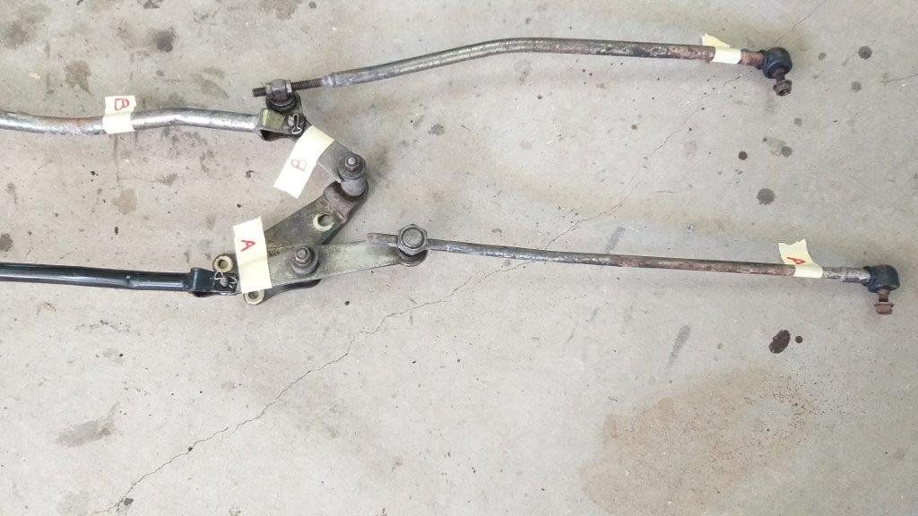
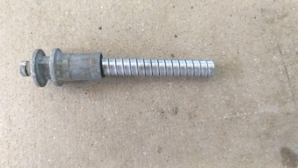
I spent a considerable amount of time under the Thames trying to find a clear route for the HiAce gate selector rods, but eventually had to concede defeat. The major stumbling block is the fact that the HiAce is a monocoque construction so there are no beefy chassis rails to contend with. In the case of the Thames there is a ruddy great chassis leg that needs to be trans versed to get from the gearbox arm to the column shift arm. I looked at modifying the intermediate pivot point on the linkage by extending the connecting rod over the top of the chassis rail thus leaving me with the shorter gearbox rod on the inside of the chassis leg and the longer column rod on the outside of the chassis leg. This could have worked if I didn't have the steering column in the way of the final connection to the column shifter. I could attempt to fabricate some kind of dog leg setup with another pivot point to get around the steering column, but I'd end up with a reverse pattern gate shift. I could incorporate another pivot point to retain the correct movement direction for the gate lever but I'm worried about over complicating the solution. So with my first attempt banished to the naughty corner I decided to investigate the possibility of using the shorter gearbox rod and pivot point from the HiAce mated to the a shorter push pull cable. The HiAce gate rod and pivot are the ones labelled A in this photo :
-
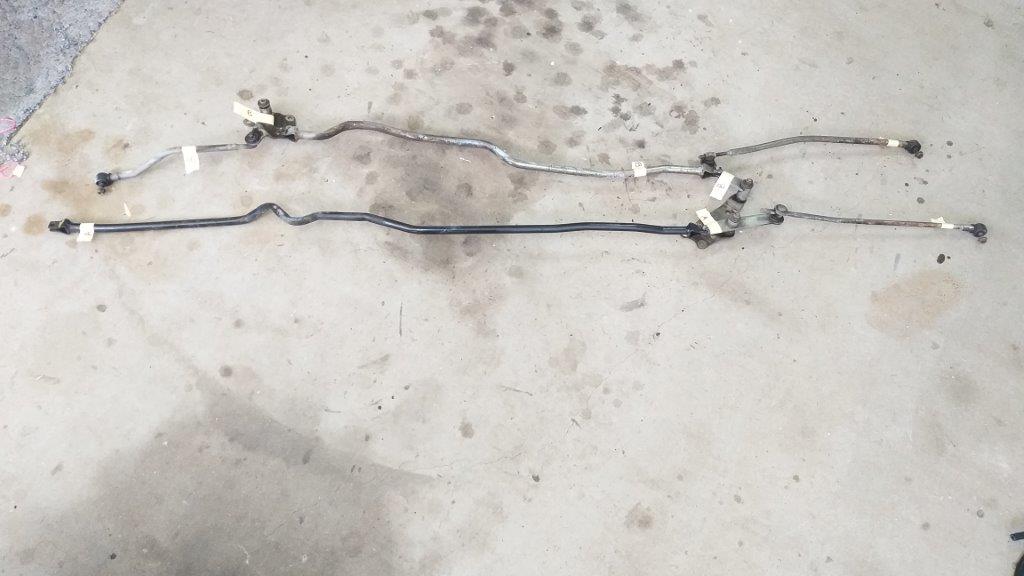
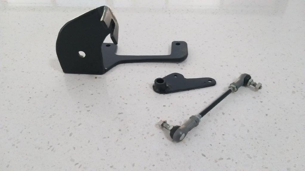
Well, it’s been over a week since my last update so that kinda bears witness to the time consuming nature of the issue that I am currently trying to resolve. Let me explain …. So spurred on by my recent success with the revised accelerator setup I decided to revisit my gear linkage setup. When I last touched on this subject I was leaning towards replacing the original Thames column shifter with the floor shifter harvested from my Mitsi Express donor. The main reason being that I just wasn’t able to get enough force applied to the gearbox gate selector to get a consistent result. I’ve got to admit that at the time this decision didn’t sit well with me at all. The column shift adds to the van’s general quirkiness and it feels like a compromise going with the floor shifter. So, with that in mind I decided to have one more go at sorting out the column shifter. To my way of thinking the issue stems from the fact that I am "losing energy" through the long push pull cable compared to the solid shift rods that the HiAce was equipped with, so my first thought was to see if I could retro fit the HiAce rods to the Thames. Started off by cleaning them up a bit as there is nothing nicer than fiddling about with clean parts. Then marked up the components so I knew which parts made up the gate selector versus those belonging to the gear selector. Ended up with this:
-
I guess by now everyone is tired of reading about my accelerator setup, so I'll close the subject off by sharing a photo of the new components with a quick splash of paint. I'm looking forward to working on something else tomorrow.
- 740 replies
-
- 12
-
-
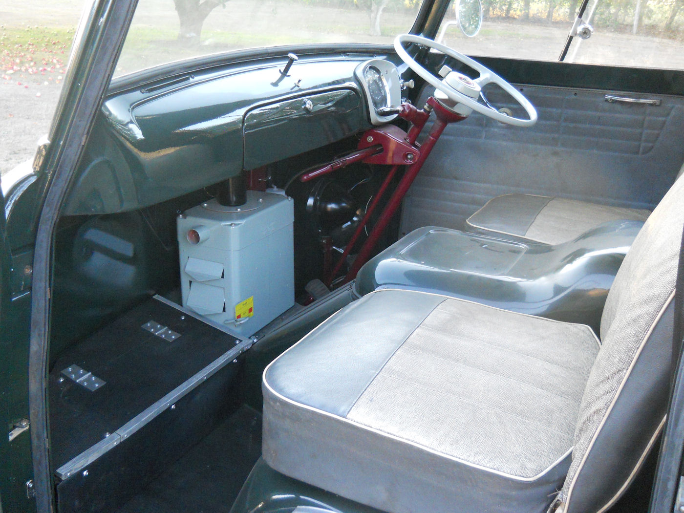
And for those who might be interested here is a pic of a UK van that has the factory option heater fitted. As you can see it was a pretty agricultural setup.
-
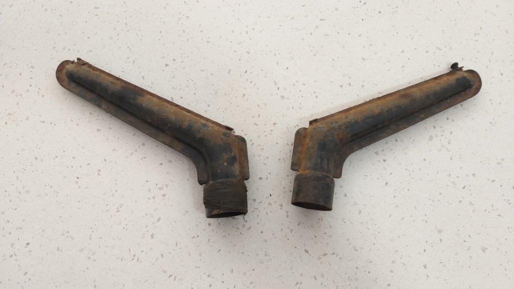
In other news a parcel arrived from the UK today. These shabby looking bits are like hen's teeth, so I was super chuffed when Sandy from the Owner's Club was able to track down a set for me. A mate of his has just stripped a rusty old wreck and luckily salvaged these. So why am I so chuffed I hear you ask ..... Well whilst all 400Es came out with the demister slots stamped into the all metal dash, only those vans fitted with the factory option cabin heater actually had the demister nozzles and associated pipework fitted. Asking around amongst the handful of Australian 400E owners that I know, it seems like none of the locally assembled vans came out with the heater / demister fitted. A few fully imported Dormobile campers that arrived here from the UK do have them. Anyway, I suppose I could have fabricated something, but I'm pleased to have the original units. Doubly chuffed as for cert here I have to have a windscreen demister fitted, so this will make the job a lot easier. I'll give them a tickle with a flapper disk and a lick of paint and they should be good to go.
-
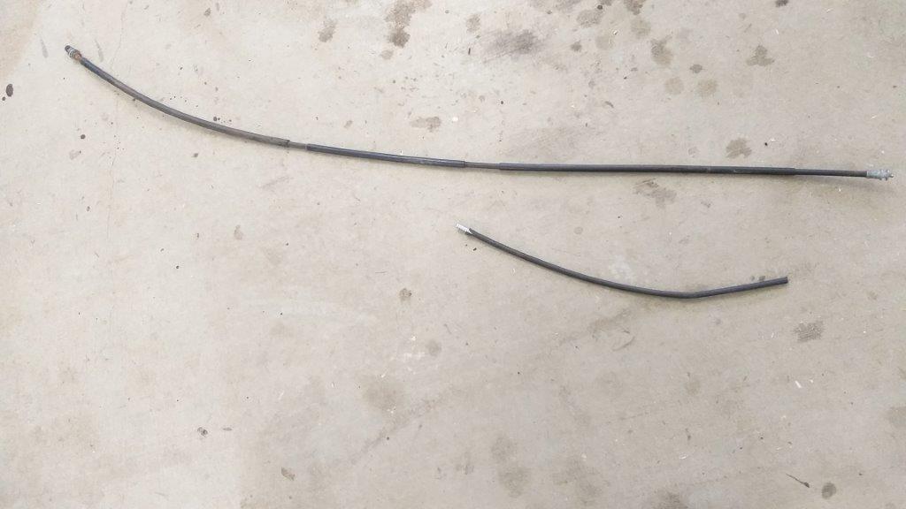
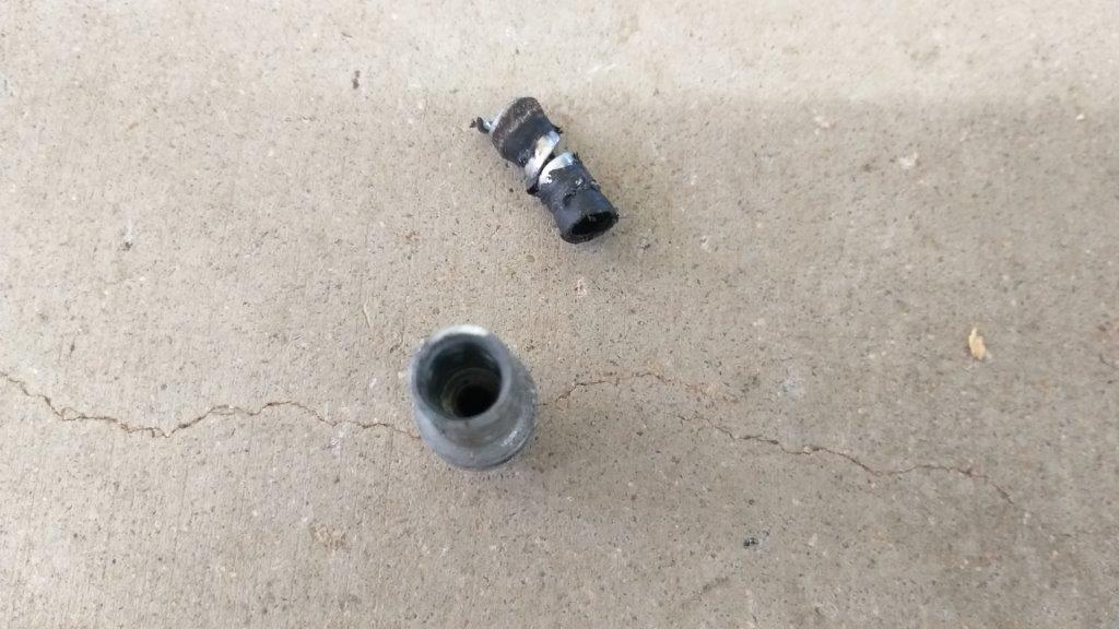
With the outer sheath now at the correct length I attempted to re-crimp the end using my vice, but only being able to tackle a set of opposite faces at a time it was starting to go pear shaped (literally) , so I decided on a Plan B which entailed smearing a bit of epoxy on the end of the outer sheath and then pushing it into the fitting. I was super careful and managed to do this without getting any epoxy in the inner opening, so that was good. I'll let it go off overnight and will assemble it all tomorrow. The inner cable will be straight forward to shorten as I'm currently using one of those universal ends that sandwiches the inner cable. Pic below shows just how much I had to cut out. Thanks for looking.
-
So first thing was to strip out the inner and take to the outer with a cut off wheel. Gave the cuts on the outer a bit of a file and a de-bur to alleviate any snagging. The end has been crimped on, but I managed to drill out the outer sheath giving me a nice clean end fitting.

.JPG.bea4154d859064dc727f050873b746d3.JPG)